john-proposal
Bạn đang xem bản rút gọn của tài liệu. Xem và tải ngay bản đầy đủ của tài liệu tại đây (2.08 MB, 43 trang )
LOGO
John W. Franklin
1
"Bistatic radars have fascinated surveillance and tracking researcher for
decades. Despite evolution from the early Chain Home radars in Britain to
today's coherent multimode monostatic radars, there remains a rich research in
bistatic and multistatic applications. The promise of quite receivers, aspect
angle diversity, and improved target tracking accuracy are what fuel this
interest.“
Mark E. Davis
Defense Advanced Projects Research Agency (DARPA)
(2007)
2
Presentation Flowchart
Bistatic
Radar
Passive
Bistatic Radar
Objective:
Explore the use of ATSC
(HDTV) as a Passive
Illuminator via
Simulation
ATSC (HDTV)
Signals
Practical
Passive Radar
Systems
3
Outline
Overview
Properties of Bistatic Radar
Geometry
Range Equation
Doppler
Cross Section
Properties of Passive Bistatic Radar
The Concept and How it Works
Why Passive Radar?
Applications
Performance Evaluation
Signal Processing
Practical System Examples
FM
Digital Video Broadcast
High Definition Television Signals
ATSC Terrestrial Transmission Standard
Research Objective
4
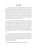
Overview-Bistatic Radar Concepts
Bistatic radar may be defined as a radar in which the transmitter and
receiver are at separate locations as opposed to conventional
monostatic radar where they are collocated.
The very first radars were bistatic, until pulsed waveforms and T/R
switches were developed
Bistatic radars can operate with their own dedicated transmitters or
with transmitters of opportunity
Radars that use more than one transmitter or receiver or both are
referred to as multistatic
5
LOGO
6
Geometry
Geometry of a Bistatic Radar is Important - it determines
many of the operating characteristics
Radar Range Equation
Doppler Velocity Equation
Radar Cross Section
Coverage area
Bistatic Angle: Angle between the illumination path and
echo path
Bistatic Angle vs. Radar Mode
β<20 degrees – (Monostatic)
20<β<145 degrees – (Bistatic)
145<β<180 degrees – (Forward/Fence)
7
Monostatic and Bistatic Geometry
Monostatic Radar Geometry Bistatic Radar Geometry
β<20 degrees
20<β<145 degrees
8
Forward/Fence Geometry
Forward/Fence Radar Geometry (limiting case)
145<β<180 degrees
9
Bistatic Radar Range Equation
2
2
2
1
44 r
A
G
r
PP
e
t
B
tr
[
[
Fraction of transmitted power
that is reflected to receiver
Fraction of reflected power that is
intercepted by receiving antenna
2
2
2
1
3
2
)4( rr
GGP
P
Brtt
r
(Bistatic Radar Equation)
where
P
r
is the received signal power
P
t
is the transmit power
G
t
is the transmit antenna gain
r
1
is the transmitter-to-target range
b
is the target bistatic RCS
r
2
is the target-to-receiver range
G
r
is the receive antenna gain
is the radar wavelength
4
2
r
e
G
A
Using: then:
Transmitted Power
10
Bistatic Doppler
Given the target velocity V and the transmitter and
receiver velocities being stationary (V
R
= V
T
= 0), the
doppler frequency shift is:
The change in the received frequency relative
to the transmitted frequency is called the
Doppler frequency, denoted by fD
Doppler shift is
proportional to the
target velocity
11
Doppler lets you separate things that are moving from things that aren’t
Bistatic Radar Cross Section
Function of target size, shape, material, angle and carrier frequency
Usually, a bistatic RCS is lower than the monostatic RCS
At some target angles a high bistatic RCS is achieved (forward scatter)
Bistatic measurements are essential to understanding the stealth characteristics of vehicles
Almost no data has appeared in the open literature, open research topic
-Low frequencies are more favorable for the
exploitation of forward scatter
-Target detection may be achieved over an
adequately wide angular range
The angular width of the scattered signal
horizontal or vertical plane:
Target cross-sectional area A gives a radar
cross-section of:
12
LOGO
13
Concepts
A Subtype of Bistatic Radar (all bistatic/multistatic analysis apply)
Geometry, Doppler, RCS
A Passive Bistatic Radar is a Bistatic Radar that does not emit any Radio
Frequency (RF) of its own to detect targets
It utilizes the already existing RF energy in the atmosphere
Examples of such sources of RF energy are Broadcast FM stations, Global
Positioning Satellites, Cellular Telephones, and Commercial Television.
When the transmitter of opportunity is another radar transmission, the
term such as: hitchhiker, or parasitic radar are often used
When the transmitter of opportunity is from a non-radar transmission,
such as broadcast communications, terms such as: passive radar, passive
coherent location, or passive bistatic radar are used
14
How does it Work?
By exploiting common RF energy such as Commercial FM Broadcasts,
as an “Illuminators of Opportunity”, scattered by a target
The scattered RF energy is received by one antenna and this signal is
then compared to a reference signal from second antenna.
By using Digital Signal Processing (DSP) techniques, target
parameters such as range, range-rate, and angle of arrival may be
determined
We are extracting typical radar information from a communication
signal
15
Idea of a Passive Bistatic/Multistatic Radar
Bistatic
Multistatic
16
Why Passive Radar?
Advantages
Lower cost, no dedicated transmitter
No need for frequency allocations
Covert (receiver), Difficulty of Jamming
Virtually immune to Anti-Radiation Missiles
Fast updates
Potential ability to detect stealth targets
Disadvantages
More Complicated Geometry
No direct control of transmitting signal
Technology is immature
17
Applications
Detection of Low Probability of Intercept (LPI)
Radar signals
Detection of Stealth Targets
Low Cost Air Traffic Control (ATC) Systems
Law Enforcement (Traffic Monitoring)
Border Crossing/Intrusion Detection
Local Metrological Monitoring
Planetary Mapping
18
Performance Evaluation
What Type of Waveforms should we use in a PBR System
Modulation Type (Analog/Digital) of the exploited signal
Analyze using the Ambiguity Function
We Need to Know
What Type of Power do we need
Signal Power Density of the exploited signal at Target
Analyze using the Bistatic Range Equation
19
Ambiguity Function
What is it used for?
As a means of studying different waveforms
To determine the range and Doppler resolutions for a specific transmission
waveform
The radar ambiguity function for a signal is defined as the modulus squared of its
2-D correlation function:
The 3-D plot of the ambiguity function versus frequency and time delay is called the radar
ambiguity diagram
Where:
- is the complex envelope of the transmitted signal
- is the time delay
- is the Doppler frequency shift
20
Radar Ambiguity Diagram
The thumbtack ambiguity function is common to noiselike or pseudonoise
waveforms. By increasing the bandwidth or pulse duration the width of
the spike narrow along the time or the frequency axis, respectively.
This shows that as we increase the bandwidth B, we have better range
resolution. Conversely if we increase the pulse width T, we increase the
doppler resolution.
Where:
B - bandwidth
T - pulse width
f
d
- doppler delay
t
d
- time delay
21
Doppler
Delay
Radar Ambiguity Diagram
The first null occurs at
The main peak of the ambiguity function corresponds to the resolution of the system in
terms of range and Doppler.
The additional peaks correspond to potential ambiguities, resulting in confusion at
choosing the correct range of the target and its velocity
22
Analog FM Waveforms
FM analysis has been performed extensively in the U.S. and in Europe
(England/Germany)
FM radio transmissions 88–108 MHz VHF band
The modulation bandwidth typically 50 kHz
Highest power transmitters are 250 kW EIRP
Range resolution c/2B = 3000 m (monostatic)
Power density = –57 dBW/m
2
(target range @ 100 km)
Existing commercial FM transmitters provide low-to-medium altitude
coverage
The ambiguity performance of FM transmissions will depend on the
instantaneous modulation
23
FM Range Resolution Variance
Variance is due to instantaneous modulation
Four types of VHF FM radio modulation over a two-second interval
24
Analog FM Ambiguity Diagram
Analog FM – Speech Ambiguity Plot
25