Network Planning, Monitoring, and Troubleshooting with Lync Server
Bạn đang xem bản rút gọn của tài liệu. Xem và tải ngay bản đầy đủ của tài liệu tại đây (2.92 MB, 148 trang )
Networking Guide
Network Planning, Monitoring, and Troubleshooting with
Lync Server
Update Published: June 2014
Updated KHI spreadsheet and CQM queries
Added the new Microsoft Call Quality Scorecard for Lync Server
Update Authors: Brandon Bernier, Kent Tilger, Andrew Sniderman and Jens Trier Rasmussen
Originally Published: May 2013
Authors: Jigar Dani, Craig Hill, Jack Wight, Wei Zhong
Contributors: Brandon Bernier, Robert Burnett, Jason Collier, Paul Cullimore, Daniel
Hernandez, James Hornby, Dave Jennings, Jonathan Lewis, Jens Trier Rasmussen, Juha
Saarinen, Marc Sanders, Joel Sisko, Nick Smith, Andrew Sniderman, Jamie Stark, Aaron Steele,
Connie Welsh, Kent Tilger, Thomas Binder
Editor: Randall DuBois
Abstract: Microsoft Lync Server 2013 communications software is a real-time unified
communications application that enables peer-to-peer audio and video (A/V) calling,
conferencing, and collaboration and relies on an optimized, reliable network infrastructure to
deliver high-quality media sessions between clients. This guide provides a model for managing
the network infrastructure for Lync Server 2013, consisting of three phases—planning,
monitoring, and troubleshooting. These phases can apply to new Lync Server deployments or to
existing deployments. In new Lync Server deployments, your organization must begin from the
planning phase. In existing deployments, your organization can start at the planning phase for
major upgrades or for integrating new sites into the Lync Server ecosystem. Organizations with
existing deployments can also begin from the monitoring or troubleshooting phases, if you are
trying to achieve a healthy state.
This document is provided “as-is”. Information and views expressed in this document, including
URL and other Internet Web site references, may change without notice.
Some examples depicted herein are provided for illustration only and are fictitious. No real
association or connection is intended or should be inferred.
This document does not provide you with any legal rights to any intellectual property in any
Microsoft product. You may copy and use this document for your internal, reference purposes.
Copyright © 2013 Microsoft Corporation. All rights reserved.
Lync Server Networking Guide
1
Contents
1. Introduction 8
1.1 Support Materials 8
1.2 Phase Overview 10
2. Planning 12
2.1 Network Discovery 13
2.1.1 Historical Metrics 13
2.1.2 Network Impairments 13
2.1.2.1 WAN Optimizers 13
2.1.2.2 Virtual Private Network (VPN) 14
2.1.2.3 Firewall Policies 15
2.1.2.4 Symmetric versus Asymmetric Links 15
2.1.2.5 Network Topology 15
2.1.3 Lync Devices 17
2.1.3.1 Power over Ethernet (PoE) 17
2.1.3.2 Virtual LAN (VLAN) 17
2.1.4 Qualified Network Devices 17
2.2 Modeling/Personas 17
2.3 Bandwidth Estimation 20
2.3.1 Call Flows 20
2.3.1.1 Peer-to-Peer Session 20
2.3.1.2 Conference Session 20
2.3.1.3 PSTN/Mediation Server Session 21
2.3.1.4 Content Sharing 21
2.3.2 Bandwidth Tables 21
2.3.2.1 Video Codec Bandwidth 23
2.3.2.2 Video Resolution Bandwidth 23
2.3.2.3 Impact of Multiple Video Streams in Lync Server 2013 25
2.3.2.3.1 Lync Server Bandwidth 25
2.3.2.4 Audio Capacity Planning for PSTN 26
2.3.3 Bandwidth Estimation for Redundant Links 26
2.4 Traffic Simulation 26
2.4.1 Simulating Estimated Amount of Bandwidth Required 27
2.4.1.1 P2P Scenarios 27
2.4.1.2 Conferencing Scenarios 27
2.4.2 Identifying Sites for Lync Server Traffic Simulation 29
2.4.3 Lync Server Real-Time Scenarios to Be Simulated 29
2.4.4 Recommended Tools for Lync Server Traffic Simulation 29
2.4.5 Traffic Simulation Best Practices 30
2.5 Call Admission Control (CAC) 31
2.5.1 Multiple Call Admission Control Systems 31
2.6 Quality of Service (QoS) 32
2.7 Network Port Usage 32
2.7.1 Manual Port Configuration Scenarios 33
Lync Server Networking Guide
2
2.7.2 Quality of Service (QoS) for Modality Types 33
2.7.3 Bandwidth Management 33
2.7.4 Internal Firewall Placement 33
2.7.5 Minimum Number of Ports for Workloads at Scale 34
2.7.6 Configuring Manual Ports for the Lync Client 34
2.7.7 Configuring Port Ranges for Application, Conferencing, and Mediation Servers 35
2.7.8 Configuring Dedicated Port Ranges for Edge Servers 37
2.7.9 Verifying Manual Port Configuration – Client Side 37
2.7.10 Verifying the UC Port Range Is Enabled for Lync Clients 38
2.7.11 Configured UC Port Range Example (from a Sample Lync-UccApi-0.UccApilog) 38
2.7.12 Verifying Manual Port Configuration – Server Side 38
2.7.13 Traffic Prioritization for Real-Time Communications 39
2.8 Wi-Fi Scenarios 39
2.8.1 Background 39
2.8.2 What Is Wi-Fi? 40
2.8.2.1 Wireless Standards 40
2.8.2.2 Wi-Fi Multimedia (WMM) 40
2.8.2.3 WAP Planning 41
2.8.3 Wi-Fi Certification for Lync Server 41
2.8.4 Wi-Fi Challenges and Recommendations 41
2.8.4.1 WAP Configuration 41
2.8.5 Next Steps 42
2.8.5.1 Simple Wi-Fi Scan 42
2.8.5.2 Spectrum Scan 43
2.8.5.3 Wi-Fi Assessment 44
2.8.5.3.1 Preassessment Questionnaire 44
2.8.5.3.2 Requirements 45
2.8.5.3.3 Assessment 45
2.8.5.3.4 Presenting Results 45
2.9 Operations 45
2.9.1 Network Change Control Process 45
2.9.1.1 Network Requirements 46
2.9.1.2 Change Management Roles 46
2.9.1.3 Change Management Process 46
2.9.2 Network Incident Management 47
2.9.3 Real-Time Applications 47
3. Deployment and Monitoring 48
3.1 Elements that Require Monitoring 48
3.1.1 Server Health 48
3.1.1.1 Common Server Health KHIs 49
3.1.1.2 Role-Specific Server Health KHIs 49
3.1.2 Network Health 50
3.1.2.1 Network Device KHIs 50
3.1.2.2 Lync Server Call Network Metrics 50
3.1.2.2.1 Packet Loss 51
3.1.2.2.2 Jitter 51
Lync Server Networking Guide
3
3.1.2.2.3 Latency 52
3.1.3 Client Health 52
3.2 Configuration Audit 53
3.2.1 IP-PSTN Gateway Configuration Drift 53
3.2.2 Lync Server Configuration Drift 53
3.2.3 Network Configuration Drift 54
3.3 Usage Trend Reporting 54
3.4 Product Features that Provide Monitoring Data 54
3.5 Third-Party Solutions that Provide Monitoring 55
4. Troubleshooting 56
4.1 Troubleshooting Scenarios 56
4.1.1 Troubleshooting a Site-Wide Issue: Lync Voice Quality - A Site Suddenly Reports Poor Audio
Quality 56
4.1.1.1 Problem Report Scenario 56
4.1.1.2 Initial Assessment 56
4.1.1.3 Data Collection 56
4.1.1.4 Problem Isolation and Root Cause Analysis 57
4.1.2 Troubleshooting an Individual Lync Voice Quality Issue 57
4.1.2.1 Problem Report Scenario 57
4.1.2.2 Initial Assessment 58
4.1.2.3 Data Collection 59
4.1.2.4 Problem Isolation and Root Cause Analysis 60
4.2 Troubleshooting Methodologies 60
4.2.1 Troubleshooting a Network Segment 61
4.2.1.1 Network Router Configuration 61
4.2.1.1.1 Quality of Service (QoS) 62
4.2.1.1.2 Rate Limiting 63
4.2.1.1.3 Speed Sensing Mismatch (Full/Auto) 63
4.2.1.1.4 Nagle Algorithm (TCP only) 63
4.2.1.1.5 Load Balancer Configuration 64
4.2.1.1.6 HTTP Proxies 64
4.2.1.1.7 Bandwidth 64
4.2.1.1.8 WAN/ISP 65
4.2.1.2 Network Hardware Issues 65
4.2.1.2.1 Bad Patch Cable 65
4.2.1.2.2 Cable Loop/BPDU Guard Protection 65
4.2.1.2.3 Router CPU Spikes 65
4.2.1.3 Wi-Fi Quality 65
4.2.1.3.1 Interference 65
4.2.1.3.2 Access Point Density 66
4.2.1.3.3 Roaming 66
4.2.1.3.4 Wi-Fi Network Adapter and Driver 66
4.2.1.4 Other Client Network Quality Issues 66
4.2.1.4.1 Mobile Broadband 66
4.2.1.4.2 IPSec 66
4.2.1.4.3 Virtual Private Network (VPN) 66
Lync Server Networking Guide
4
4.2.1.4.4 Forced TCP Connection 67
4.2.1.4.5 ISP/Internet 67
4.2.1.5 Client Endpoint Performance 67
4.2.1.5.1 Power-Saving Mode 67
4.2.1.5.2 USB Hub/Cable 67
4.2.1.5.3 Drivers/DPC Storm 67
4.2.1.6 Server Endpoint Performance 68
4.2.1.6.1 Antivirus/Port Scanning Software 68
4.2.1.6.2 Performance Counter Collection and Logging 68
4.2.1.6.3 Network Adapter Configuration 68
4.2.1.6.4 Concurrent Call Load 69
4.2.1.6.5 Virtualization 69
4.2.2 Troubleshooting Device Issues 69
4.2.2.1 Built-in Sound Cards 69
4.2.2.1.1 Microphone Boost 69
4.2.2.1.2 Digital Signal Processing (DSP) 70
4.2.2.2.3 Noise 70
4.2.2.2 USB Devices 71
4.2.2.2.1 USB Host Device Driver 71
4.2.2.2.2 USB Hubs and Cabling 71
4.2.2.2.3 PC BIOS 71
4.2.2.3 Other Device Issues 71
4.2.2.3.1 Harmonics 72
4.2.2.3.2 Acoustic Isolation 72
4.2.2.3.3 Electrical Isolation 72
4.2.3 Troubleshooting Environmental Issues 72
4.2.3.1 Noise 72
4.2.3.1.1 Heating, Ventilating, and Air Conditioning (HVAC) Noise 72
4.2.3.1.2 Laptop Fan/Hard Drive 72
4.2.3.1.3 Typing 72
4.2.3.2 Microphone Positioning and Audio Device Selection 73
4.2.4 Troubleshooting IP-PSTN Gateways 73
4.2.4.1 Comfort Noise 73
4.2.4.2. Voice Activity Detection/Silence Suppression (VAD/SS) 73
Appendix A. Lync Audio Quality Model 74
A.1 Lync Audio Pipeline 74
A.1.1 Analog Audio Source 75
A.1.2 Analog Audio Capture 75
A.1.3 Analog-to-Digital Conversion (ADC) 75
A.1.4 Digital Signal Packet Capture 76
A.1.5 Digital Signal Preprocessing (DSP) 76
A.1.6 Encoding 76
A.1.7 Encryption 77
A.1.8 Protocol Encapsulation 77
A.1.9 Transmission 77
A.1.9.1 Jitter 77
Lync Server Networking Guide
5
A.1.9.2 Loss 78
A.1.9.3 Delay 78
A.1.10 Reception 78
A.1.11 Decryption 78
A.1.12 Decoding 78
A.1.13 Reassembly, Buffering, and Healing 79
A.1.15 Post processing 79
A.1.16 Playback 79
A.1.17 Digital-to-Analog Conversion (DAC) 79
A.1.18 Analog Audio Render 79
Appendix B. Lync Server QoE Reporting 80
B.1 Lync 2010 QoE Database Schema 80
B.2 QoE Table Join View Example 81
B.3 QoE Metrics Review 82
B.3.1 End-to-End Metrics 82
B.3.2 Endpoint Metrics 83
B.3.3 Configuration Parameters 83
B.3.3.1 UserAgent Field 83
B.3.4 Event Ratios 83
B.4 Managing Lync Server Quality 83
B.4.1 Corporate Average Audio Quality 83
B.4.2 ClassifiedPoorCall 83
B.4.3 Media Quality Summary Report 84
B.4.4 Managed versus Unmanaged Infrastructure Reporting 87
B.5 Server-Server Reports 88
B.5.1 AV MCU 88
B.5.2 Mediation Server 88
B.5.3 IP-PSTN Gateway 88
B.5.4 AV MCU-Mediation Server Report Example 88
B.5.4.1 Temporary Views 91
B.5.4.2 Counting Poor Calls 91
B.5.4.3 Caller/Callee Handling 91
B.5.5 Mediation Server-IP PSTN Gateway Report Example 91
B.6 Subnet Reports 93
B.6.1 Wired Subnet Report Example 94
B.6.2 Wireless Subnet Report Example 96
B.7 Linking to External Data Sources 96
B.8 Trending and Data Retention 97
B.9 Using User Experience Metrics 97
B.9.1 Mean Opinion Score (MOS) 100
B.9.2 Network MOS (NMOS) versus NMOS Degradation 101
B.10 Other Reporting Examples 101
B.10.1 Device Queries 101
Appendix C. Call Quality Methodology – a practical approach 105
C.1 Approach and Concepts 105
Lync Server Networking Guide
6
C.1.1 Server Plant 108
C.1.2 Endpoints 110
C.1.3 Last Mile 111
C.1.4 Service Management 112
C.2 Server Plant Breakdown 113
C.2.1 Server Health 113
C.2.1.1 Assert Quality 113
C.2.1.2 Achieve Quality 113
C.2.1.3 Maintain Quality 113
C.2.2 Server-to-server reports: AV MCU to Mediation Server and Mediation Server to Gateway 114
C.2.2.1 Assert Quality 115
C.2.2.2 Achieve Quality 115
C.2.2.3 Maintain Quality 115
C.2.3 IP-PSTN Gateway Health 115
C.2.3.1 Assert Quality 115
C.2.3.2 Achieve Quality 116
C.2.3.3 Maintain Quality 116
C.3 Endpoints Breakdown 116
C.3.1 Device 116
C.3.1.1 Assert Quality 117
C.3.1.2 Achieve Quality 117
C.3.1.3 Maintain Quality 117
C.3.2 System 117
C.3.2.1 Assert Quality 118
C.3.2.2 Achieve Quality 118
C.3.2.3 Maintain Quality 119
C.3.3 Media Path – VPN & Relay 119
C.3.3.1 Assert Quality 120
C.3.3.2 Achieve Quality 120
C.3.3.3. Maintain Quality 120
C.3.4 Media Path – Transport 120
C.3.4.1 Assert Quality 121
C.3.4.2 Achieve Quality 121
C.3.4.3 Maintain Quality 121
C.4 Last Mile Breakdown 121
C.4.1. Wired 122
C.4.1.1 Assert Quality 122
C.4.1.2 Achieve Quality 122
C.4.1.3 Maintain Quality 122
C.4.2 Wireless 123
C.4.2.1 Assert Quality 123
C.4.2.2 Achieve Quality 123
C.4.2.3 Maintain Quality 123
C.5 Microsoft Call Quality Methodology Scorecard for Lync Server 123
C.5.1 Stream Distribution View 124
C.5.2 Trending Views 125
Lync Server Networking Guide
7
C.5.3 The Scorecard 126
C.5.4 Top Issues 127
C.6 Summary 127
Appendix D. Troubleshooting Poor Streams 129
D.1 RTP and RTCP (Packet Loss Troubleshooter) 129
D.1.1 RTP 129
D.1.2 RTCP 130
D.1.3 Receiver Report and Sender Report header structure 130
D.3 Example Scenario – Investigate Packet Loss reported between Mediation Server and Gateway . 133
Appendix E. Troubleshooting Duplex and Speed Sensing Mismatch (Full/Auto) 138
Appendix F. Tools 139
F.1 Collect Logs 139
F.2 Debugging Tools for Windows 139
F.3 err.exe 139
F.4 Error String Display (CSError.exe) 139
F.5 Microsoft Exchange Troubleshooting Assistant 140
F.6 Log Parser 141
F.7 Lync Best Practices Analyzer 141
F.8 Lync Client Logging 141
F.9 Lync Server 2010 Logging Tool 141
F.10 Microsoft Product Support (MPS) Reports 142
F.11 Network Monitor 143
F.12 Network Monitor Parsers 143
F.13 OCStracer.exe 143
F.14 PortQryUI 144
F.15 ProcDump 144
F.16 Process Explorer 144
F.17 Process Monitor 144
F.18 Remote Connectivity Analyzer 144
F.19 Snooper 144
F.20 TextAnalysisTool.NET 145
F.21 Unified Messaging Diagnostics Logging 145
F.22 XMLNotePad 146
Lync Server Networking Guide
8
1. Introduction
Microsoft Lync Server 2013 communications software is a real-time unified communications application
that enables peer-to-peer audio and video (A/V) calling, conferencing, and collaboration and relies on an
optimized, reliable network infrastructure to deliver high-quality media sessions between clients.
This paper provides a model for managing the network infrastructure for Lync Server 2013, consisting of
three phases:
Planning
Monitoring
Troubleshooting
These phases can apply to new Lync Server deployments or to existing deployments. In new Lync Server
deployments, your organization must begin from the planning phase. In existing deployments, your
organization can start at the planning phase for major upgrades or for integrating new sites into the Lync
2013 ecosystem. Organizations with existing deployments can also begin from the monitoring or
troubleshooting phases, if you are trying to achieve a healthy state.
1.1 Support Materials
In addition to this Word document, the .zip file you downloaded also contains the support files referred to
within this document, including text files with the sample queries, a spreadsheet with KHI information that
is referred to in section C.2.1.1 Assert Quality, and a Windows PowerShell script
(Create_KHI_Collection.ps1) to collect PerfMon information.
The following files are included in the .zip file:
Lync_Server_Networking_Guide_v2.2.docx (this document)
Microsoft Call Quality Methodology Scorecard for Lync Server – EULA.docx
Microsoft Call Quality Methodology Scorecard for Lync Server
CQM.ps1
GetSqlDateFormat.ps1
Microsoft Call Quality Methodology Scorecard for Lync Server.docx
Microsoft Call Quality Methodology Scorecard for Lync Server.xlsx
Queries
PoorStreamCondition_CQM
PoorStreamCondition_ClassifiedPoorCall
PoorStreamCondition_Custom
Lync 2010
Endpoint_0_Device_2010 v14.txt
Endpoint_1_System_2010 v14.txt
Endpoint_2_Relay_2010 v14.txt
Endpoint_2_VPN_2010 v14.txt
Lync Server Networking Guide
9
Endpoint_3_Transport_2010 v14.txt
LastMile_0_Wired_2010 v14.txt
LastMile_1_Wireless_2010 v14.txt
Plant_1_AVMCU_Mediation_2010 v14.txt
Plant_2_Mediation_Gateway_2010 v14.txt
Trend_1_AVMCU_Mediation_2010 v14.txt
Trend_2_Mediation_Gateway_2010 v14.txt
Trend_3_Wired_2010 v14.txt
Trend_4_Wired_P2P_2010 v14.txt
Trend_5_Other_Wired_2010 v14.txt
Trend_6_Other_Wireless_2010 v14.txt
Trend_7_VPN_2010 v14.txt
Trend_8_External_2010 v14.txt
Trend_9_Wireless_2010 v14.txt
Trend_10_Wireless_P2P_2010 v14.txt
Trend_11_Total_2010 v14.txt
Util_1_Users_Devices_Streams_2010 v14.txt
Lync 2013
Endpoint_0_Device v14.txt
Endpoint_1_System v14.txt
Endpoint_2_Relay v14.txt
Endpoint_2_VPN v14.txt
Endpoint_3_Transport v14.txt
LastMile_0_Wired v14.txt
LastMile_1_Wireless v14.txt
Plant_1_AVMCU_Mediation v14.txt
Plant_2_Mediation_Gateway v14.txt
Trend_1_AVMCU_Mediation v14.txt
Trend_2_Mediation_Gateway v14.txt
Trend_3_Wired v14.txt
Trend_4_Wired_P2P v14.txt
Trend_5_Other_Wired v14.txt
Trend_6_Other_Wireless v14.txt
Trend_7_VPN v14.txt
Lync Server Networking Guide
10
Trend_8_External v14.txt
Trend_9_Wireless v14.txt
Trend_10_Wireless_P2P v14.txt
Trend_11_Total v14.txt
Util_1_Users_Devices_Streams v14.txt
KHIs
Lync Server 2010
Create_KHI_Collection.ps1
Lync_Server_2010_Key_Health_Indicators.xlsx
Lync Server 2013
Create_KHI_Collection.ps1
Lync_Server_2013_Key_Health_Indicators.xlsx
1.2 Phase Overview
During the planning phase, your organization must determine the requirements of deployment either for
the entire organization, or for specific sites when they are added. This guide assumes that little or no Lync
Server infrastructure exists to generate the data for projections and for health and capacity assessments.
Therefore, this phase generally involves modeling the user requirements and using tools to assess
capacity and health. For example, your organization may decide that a site requires a certain amount of
bandwidth for Lync Server voice and video traffic. You may then choose to use Quality of Service (QoS)
data to help ensure adequate priority for this traffic.
During the monitoring phase, your organization maintains the health of the deployment, uses existing
Lync Server telemetry where possible, and fills the gaps by using third-party tools. The process involves
identifying the elements that need monitoring, and creating action plans for reacting to alerts based on
key health indicators (KHIs) and network quality views. If you find issues, the organization enters the
troubleshooting phase. Following the earlier example from the planning phase, your organization may
decide to use Lync Server Quality of Experience (QoE) data to help ensure that a site’s network health is
within designated targets. You may also decide to use third-party network management tools to help
ensure that QoS settings are continuously configured to specification.
During the troubleshooting phase, your organization determines the root causes of any issues arising
from monitored entities or from end-user support escalations. If appropriate monitoring solutions are in
place, your troubleshooting efforts will be significantly reduced. Continuing with the earlier example, if
most of the core Lync Server and network infrastructure is correctly provisioned and monitored, you can
start troubleshooting at the point closest to where the issue is occurring, rather than from the core
infrastructure. For example, if a user complains about a poor audio experience, the troubleshooting will
start from the user’s endpoint.
As these scenarios show, the planning, monitoring, and troubleshooting phases are strategies to deal
with the same set of issues by using the tools and data available at each respective phase. The
information contained in this guide will apply to an organization in any phase or scope of a Lync Server
deployment.
Finally, this guide describes the primary concept of breaking down the Lync Server deployment and
network infrastructure into managed and unmanaged spaces. The managed space includes your entire
Lync Server Networking Guide
11
inside wired network and server infrastructure. The unmanaged space is the wireless infrastructure and
the outside network infrastructure. Dividing the deployment and infrastructure into these two spaces
significantly increases the clarity of your data and helps your organization focus on workloads that will
have a measurable impact on your users’ voice and video quality. This is because your users have a
different expectation of quality if the call is placed on infrastructure that you own (managed) versus
infrastructure that is partly under the control of some other entity (unmanaged). This is not to say that
wireless users are left to their own devices to have excellent Lync Server experiences. As with the
dependency between the planning, monitoring, and troubleshooting phases, improving voice quality in the
unmanaged space requires you to have high quality in the managed space. Whether wireless (Wi-Fi) is
considered managed or unmanaged space is up to your organization. The techniques to achieve a
healthy environment are different in the two spaces, as are the solutions. This paper includes examples of
managing unmanaged call quality.
The following table shows examples of Lync Server call scenarios and their classification into the
managed and unmanaged spaces.
Lync Server Call Scenarios in Managed and Unmanaged Spaces
Scenario
Classification
User calls from a hotel Wi-Fi connection
Unmanaged
Two users call each other from their wired desktop PCs inside the corporate firewall
Managed
User makes a PSTN call from his wired desktop PC inside the corporate firewall
Managed
User joins a conference from her wired desktop PC inside the corporate firewall
Managed
User on Wi-Fi calls another user
Unmanaged
User from home joins a conference
Unmanaged
Lync Server Networking Guide
12
2. Planning
In exploring topics related to network planning, two primary questions will be addressed:
How does Lync Server affect my network?
How does my network affect Lync Server?
The goal of this networking guide is not to teach you to become a Lync Server expert, nor to teach you
how to become a networking expert. Rather, this guide describes areas related to enterprise data
networking that you should consider during the predeployment planning phase of your Lync Server
adoption.
As a key area in any networking planning activity related to bandwidth planning, we investigate the
exploratory questions that you should be asking your organization in order to model user behavior. We
also direct you to the public bandwidth calculator as a tool available for use, and to the default usage
models, defined in the bandwidth calculator, as starting points.
In addition, we describe how your existing environment can affect the behavior of Lync Server. For
example, topology choices, multiple Multiprotocol Label Switching (MPLS) suppliers, or infrastructure
such as WAN optimization devices, particularly if overlooked during the planning process, can become
real challenges as your deployment evolves.
We also discuss how to make use of the Microsoft Partner Community in order to deliver the Lync Server
Network Readiness assessment methodology in your environment. This methodology quantitatively
assesses your organization’s ability to use Lync Server by walking you through the network discovery,
usage modeling, traffic simulation, and analysis phases, during your engagement.
Network planning for Lync Server consists of the following areas:
Network assessment methodology
o Network discovery
o Modeling/personas
o Bandwidth estimation
o Traffic simulation
Call Admission Control (CAC)
Quality of Experience (QoE)
Quality of Service (QoS)
Network port usage
Wi-Fi scenarios
Operations
Miscellaneous planning questions
We highly recommend a network assessment as a first step before deploying Lync Server. A network
assessment provides you with insight into the readiness of your network infrastructure for supporting an
excellent user experience, while using Lync Server for real-time communications. Our customers often
ask, "Is my network infrastructure ready to support Lync Server?” Our approach helps to answer this
critical predeployment question. The network assessment uses a proven methodology to:
Discover your environment.
Lync Server Networking Guide
13
Model your usage patterns and usage scenarios by using information collected during
discovery, with the help of the Lync Bandwidth Calculator.
Simulate the anticipated Lync Server traffic volumes by using real media streams for a full
seven days.
Analyze the underlying network infrastructure performance characteristics to determine your
readiness in deploying Lync Server.
The outcome of the network assessment answers the question, “Is my network infrastructure ready to
support Lync Server?” by providing a quantitative analysis of your network infrastructure’s performance.
2.1 Network Discovery
The objective of network discovery is to ascertain, discuss, and document the current state of your
corporate network. With discovery, the goals are to reveal potential sources of network impairments, raise
awareness of Lync Server traffic flows, and offer guidelines for network devices.
2.1.1 Historical Metrics
Before you can understand the impact that additional Lync Server traffic will have on your network, you
need to determine your baseline values. How much traffic is already on your network? Are your fixed-size
priority queues fully used, but your overall links are not? Collecting historical usage data for each WAN
link is very important. For each WAN link, you should collect:
Link speed and type
Bandwidth monitoring per WAN link
Number of traffic queues, and queue sizes
Number of users per network site
Historical data provides valuable information for usage levels and reveals potentially oversubscribed links.
This kind of information acts as a warning for serious network congestion and dropped calls, both of
which can have a direct impact on Lync Server as a real-time traffic application. When gathering historical
measurements for a WAN link, make sure that you’re able to collect data from each QoS queue on that
WAN link. You may find that your WAN link overall usage is satisfactory, but that your fixed-size priority
queue doesn’t have enough additional capacity to accommodate the additional proposed Lync Server
traffic volumes. You should also collect the following monitoring data for analysis:
Bandwidth usage over the past three months
o Average busy hour traffic
o Peak bandwidth usage
Network issues over the past 12 months
2.1.2 Network Impairments
The following topics describe different network conditions that can affect Lync Server traffic.
2.1.2.1 WAN Optimizers
WAN optimizers (or packet shapers) are typically used for mitigating issues caused by high delays or low
network bandwidth.
Lync Server Networking Guide
14
WAN optimization is a term generally used for devices that employ different techniques to enhance data
transfer efficiency across WANs. Traditionally used optimization methods include caching, compression,
protocol substitution, different forms of bandwidth throttling, and forward error correction (FEC).
It’s critical for Lync Server media traffic that all WAN optimizers are bypassed, and that any outside
attempt to control Lync Server media traffic is disabled. It’s also important to note that we’ve seen WAN
optimization devices with outdated firmware/software cause packet loss in one-direction traffic, due to
high CPU usage.
When establishing a media session, Lync Server uses Session Description Protocol (SDP) for setting up
the initial codec between endpoints. During the media session between endpoints, real-time transport
protocol (RTP) is used for transferring the media stream, and real-time transport control protocol (RTCP)
is used for controlling media flow. The RTCP monitors RTP traffic. This information is used, among other
things, to negotiate possible codec changes during the session.
Lync Server includes a bandwidth management mechanism—call admission control (CAC)—that
determines whether to enable audio/video sessions, based on available network capacity. CAC is able to
reroute call flows by using the Internet or the Public Switched Telephone Network (PSTN), if available.
In addition, WAN optimizers can cause network delays by inspecting, queuing, and buffering packets at
network ingress points.
2.1.2.2 Virtual Private Network (VPN)
Virtual private networks (VPNs), specifically, split-tunnel VPNs, are commonly used for securing external
connections when users are outside the corporate network. VPNs technically extend an organization’s
private network by transferring encrypted traffic with tunneling protocols.
When users initiate a VPN connection, the traffic is sent through the VPN tunnel. This additional tunneling
layer affects Lync Server traffic by increasing network latency and jitter. Encrypting and decrypting Lync
Server traffic can potentially degrade a VPN concentrator, and can also affect the user experience.
All Lync Server traffic is encrypted. SIP signaling uses Transport Layer Security (TLS) for client-server
connections and all media traffic is encrypted by using secure real-time transfer protocol (SRTP). Lync
traffic does not need an extra encryption layer through a VPN tunnel, unless there is a specific need for
dual-layer security.
Lync Server uses the Interactive Connectivity Establishment (ICE) protocol to provide different media
paths between Lync Server endpoints and servers. Because an endpoint-initiated media session is not
aware of the receiving endpoint’s location, ICE protocol helps by providing a list of candidates based on
IP addresses and media ports and attempting to create media sessions between them. There is a specific
candidate order, as follows, in which an ICE protocol tries to validate the media path. If a connection is
validated, ICE protocol stops checking, and the media session is opened:
1. User Datagram Protocol (UDP) local or host IP address.
2. UDP network address translation (NAT) public IP address.
3. UDP relay through public IP of Lync audio/visual (A/V) Edge.
4. Transport Control Protocol (TCP) relay through public IP of Lync A/V Edge, if UDP is not
available.
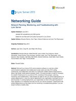
Consider the scenario where both Lync users are located outside the corporate network. They each have
their own individual VPN tunnels, and so Lync Server media traffic is affected twice by the VPN overhead.
Lync Server Networking Guide
15
Client VPN Solution
Client VPN Solution
External Firewall
User B
User A
Edge Server Pool
Internal Lync
Servers
Lync Users External to Corporate Network and VPN Overhead
The solution is to use a split-tunnel VPN with Lync Server. In a split-tunnel VPN configuration, all IP
addresses that are used by the Lync Server environment are excluded, so that traffic to and from those
addresses is not included in the VPN tunnel. You should also check the configuration for your VPN
solution against vendor documentation.
2.1.2.3 Firewall Policies
Lync Server uses a variety of workloads—presence, instant messaging, audio, video, application sharing,
web conferencing, and persistent chat. These workloads use multiple protocols (SIP, SDP, SRTP,
SRTPC, Persistent Shared Object Model (PSOM), ICE, and HTTPS). Modern corporate networks are
extensively secured and segmented by using firewalls. To minimize the impact of firewalls on Lync Server
traffic, make sure that the performance of your devices and the protocol support of your firmware and
software are at the required levels.
Handling firewall configuration for Lync Server can be challenging, and misconfiguration can cause issues
with Lync Server traffic flows. You can minimize this risk by properly planning port configuration and by
documenting it in detail. For several useful tools that can help with firewall configuration, see "Determine
External A/V Firewall and Port Requirements" at
2.1.2.4 Symmetric versus Asymmetric Links
In a symmetric link, network traffic is transmitted outbound and inbound with an equal bandwidth rate.
Conversely, an asymmetric link uses different bandwidth rates upstream and downstream. The most
common scenario for an asymmetric digital subscriber line (ADSL) is a higher bandwidth inbound as
compared to outbound.
ADSL connections are not suitable for a corporate network, particularly when real-time applications are
used. If an ADSL connection is the only option, remember that asymmetric links force Lync Server
endpoints to use lower quality codecs, lower video resolution, and slower frame rates upstream than
downstream. Also, a Lync Server deployment that uses CAC must adjust policies according to the slower
link speed.
2.1.2.5 Network Topology
Understanding your network topology is essential when planning for Lync Server. Lync Server uses the
following specific traffic call flows:
Lync Server Networking Guide
16
Peer—This traffic flow uses a site-to-site connection in scenarios where both participants are
internal Lync users. If external or federated users are involved, peer-to-peer connections are
routed through the Internet connection.
Conferencing—This traffic flow is created between the network’s site to a data center.
PSTN—This traffic flow initiates from a Lync client to the PSTN.
The topology of your corporate network determines how Lync Server traffic flows influence bandwidth
requirements. The two topologies that follow are examples of how different topologies are affected by
Lync Server traffic flows.
The following figure shows a corporate network with two MPLS carriers and a single interconnection in
one geography. Every time corporate users open a peer-to-peer media session over to another MPLS, a
network interconnection is used. There is a potential for network delay or jitter with peer-to-peer traffic.
MPLS A MPLS B
Corporate Network with Two MPLS Carriers and a Single Interconnection in One Geography
The following figure shows a corporate network with a hub-spoke mixed with an MPLS topology.
Estimating Lync Server bandwidth is difficult because hub sites handle a large part of traffic for spoke
sites, but not all of it.
MPLS
Corporate Network with Hub-Spoke Mixed with MPLS Topology
Lync Server Networking Guide
17
2.1.3 Lync Devices
Lync Server includes Microsoft Lync Phone Edition communications software, which runs on qualified
devices and provides traditional and advanced telephony features, integrated security, and manageability.
Lync Server supports the following type of unified communication (UC) phones:
Desk phones that are handset IP, or USB devices that are designed to be used by
employees at their desks.
Conferencing devices that are hands-free IP, or USB phones that are designed to be used in
meeting rooms.
Common area phones that are handset IP phones, designed to be used in shared areas.
2.1.3.1 Power over Ethernet (PoE)
IP phones running Lync Phone Edition support Power over Ethernet (PoE). To take advantage of PoE,
the switch must support PoE802.3af or 802.3at.
Consider Lync voice resiliency carefully during network planning. If your deployment includes IP phones,
don’t overlook the possibility of a power failure. It is crucial that your PoE infrastructure maintains
uninterrupted power.
2.1.3.2 Virtual LAN (VLAN)
Virtual LANs (VLANs) work as broadcast domains created by switches. VLANs are very effective for
addressing space management, particularly when you are deploying a large number of IP phones. There
are two methods to deliver VLAN information for IP phones:
Link Layer Discovery Protocol (LLDP)
Dynamic Host Configuration Protocol (DHCP)
All Lync-certified IP phones support Link Layer Discovery Protocol-Media Endpoint Discovery (LLDP-
MED). To use LLDP-MED, the switch must support IEEE802.1AB and ANSI/TIA-1057. For example, the
LLDP-MED delivers VLAN ID, switch, and port information to IP phones. In addition, the LLDP-MED can
be deployed for location lookups used by E.911.
The Lync Phone Edition devices can also use DHCP to obtain a VLAN identifier.
2.1.4 Qualified Network Devices
For a list of Lync qualified network devices, see "Infrastructure qualified for Microsoft Lync" at
2.2 Modeling/Personas
The definition of a persona is the process of analyzing existing usage data, and then using this data to
calculate the potential load on a new system. To fully explain the process, we need to introduce some
terminology that you’ll see in the Lync Bandwidth Calculator. For details, see "Lync 2010 and 2013
Bandwidth Calculator" at
Usage scenarios describe different ways that users communicate by using Lync. For instance, a peer-to-
peer audio call or a video conference are examples of usage scenarios.
A usage model represents a collection of data associated with specific users, which can help you
customize and adapt a new system to your users’ specific needs. For example, the usage model that is
associated with public switched telephone network (PSTN) calling defines "Medium" users, or users in the
medium usage category, as having a maximum of 10 percent concurrent calls to PSTN at your
organization’s busiest time.
Lync Server Networking Guide
18
A persona is a logical grouping of users based on the behavior that they exhibit when using a specific
functionality. For example, a group of users may have "Medium" PSTN calling patterns, but “High” video
conference usage. Another group of users may have no video usage scenarios at all. In the Lync Server
Bandwidth Calculator, you can define up to 10 personas for your organization. In practice, however, we
typically see four to five unique personas.
To begin the process of usage modeling, you should ask a number of general questions:
How many site locations are there?
How many users are at each site location?
How many users will always be remote?
What are the future growth estimates?
What sort of WAN technology/topology is deployed?
What is your overall WAN link speed?
What is the maximum/current available bandwidth for Lync traffic per WAN link?
Using predefined usage models is a good starting point, and the Lync Bandwidth Calculator provides
useful baselines, based on data from real customers. The challenge with a common usage model is that
no two companies (or users) use communications the same way. Modifying your usage models and
personas based on real usage data from existing systems is a critical step towards helping to ensure the
accuracy of your planning activities.
A key ingredient in defining personas is to review the existing private branch exchanges (PBXs) or real-
time communications system infrastructure capacity. This data helps to validate any personas and usage
models that you create. It also helps to indicate any future capacity planning requirements for Lync
servers, and other adjunct systems required. Evaluate the following information, if available, for usage
modeling:
Number of PBXs implemented.
Number of public switched telephone network (PSTN) channels provisioned.
Number of any intersite tie connections between PBXs, or whether intersite calls are made
through the PSTN.
Number of users at each location.
Call data records (CDRs) for PSTN traffic usage.
Usage statistics, such as the maximum number of concurrent calls during the busy hour:
o Total number and usage of PSTN channels at each site
o Trunk usage for intersite connections
The collected information helps you validate the models that you’ll use for estimating two of the three
major call flows—concurrent PSTN calls and peer-to-peer calls.
Data Collection to Validate Models for Estimating Call Flows
Lync Server Networking Guide
19
Additionally, if an existing dial-in conferencing provider provides audio-conferencing services, you can
probably access detailed usage reports used as part of the billing process. This usage data is valuable as
a tool to help you adjust personas and usage models for actual historical usage statistics regarding
general conferencing behavior.
Collect the following information:
Current location of the conference bridge in use. Although this is not directly relevant for the
usage modeling, you’ll need to know whether the conferencing media flow patterns will be
changing on the network. Because conference traffic volumes are significant, changing the
location of the conference bridge can affect network planning and design.
Maximum number of conferencing ports used.
Peak conferencing usage in the last 12 months.
Average maximum number of concurrent conferences, including the number of participants
when that maximum occurs.
Average meeting size.
Average meeting duration.
Total minutes of conferencing used per day and per month.
If available, how many internal users versus external users joined the conference bridge.
You’ll need similar information for any video conferencing systems in the infrastructure. Pay specific
attention to the desktop video endpoints and codecs in use, and be sure to ask these questions:
What is the maximum video resolution for executive video conferences: HD or VGA?
What is the base video quality to be used: VGA or CIF?
Do you plan to integrate with Lync?
When defining personas, the fewer assumptions that you make about the potential usage of the new
system, the more accurate your bandwidth and capacity calculations will be.
The default persona definition should assume that users will use all Lync Server modalities with a
Medium usage model. Using this approach helps to ensure that you can turn off modalities in your
modeling to reduce traffic volumes, rather than being surprised by an omission later in the process.
We previously described a persona as a logical group of users who behave in a similar manner when
using a specific functionality. The Lync Bandwidth Calculator includes usage models for each of the
following usage scenarios:
Maximum concurrency of x% of the user base using instant messaging and presence
Maximum concurrency of x% of the user base using peer-to-peer audio
Maximum concurrency of x% of the user base using peer-to-peer video
Maximum concurrency of x% of the user base using audio conferencing
Maximum concurrency of x% of the user base using video conferencing
Maximum concurrency of x% of the user base using desktop sharing
Maximum concurrency of x% of the user base using PSTN audio
Maximum concurrency of x% of the user base working remotely
Lync Server Networking Guide
20
This usage model can then be adjusted, based on how you anticipate your users behaving, and on
historical usage statistics from existing systems.
You can use overall usage modeling and user personas for future capacity planning in Lync Server and
other infrastructures. After you’re in production, the data on system usage becomes available through the
Lync Server Monitoring and Reporting feature. You can then use this data to validate the accuracy of your
original personas and bandwidth estimations, and to predict future requirements.
2.3 Bandwidth Estimation
What is the potential impact of Lync Server on your network?
Bandwidth estimation is the key consideration when deploying Lync Server. Actually, network estimation
would be a more apt term, because the communication streams within Lync Server rely more on latency
and packet loss than they do on raw available network bandwidth.
To understand the role of network estimation, you must also recognize the various communication flows
within Lync Server. Coupled with the user personas, you can then use this information within the Lync
Bandwidth Calculator to understand, per modality, the volume of traffic that using Lync Server will likely
generate.
The Lync Bandwidth Calculator is continuously updated to reflect feedback from internal testing and also
from actual customer-deployed Lync projects. Therefore, the latest version of this spreadsheet can be
considered the most accurate view of network bandwidth usage. For details, see "Lync 2010 and 2013
Bandwidth Calculator" at
For a graphical overview of all the protocols in use within Lync Server, see:
"Microsoft Lync Server 2010 Protocol Workloads Poster" at
"Microsoft Lync Server 2013 Protocol Workloads Poster" at
2.3.1 Call Flows
Within any IP-based unified communications (UC) solution, there are certain characteristic call-flow
scenarios that affect traffic modeling results and traffic simulation. Scenarios include peer-to-peer calls,
conference calls, and PSTN/PBX calls. Each scenario has different media paths, and must be modeled
and or simulated to determine future load requirements. There are other call-flow scenarios within the UC
solution—specifically, those of remote users or federated communications. The following scenarios focus
on planning for enterprise environments and managed networks. For details about these scenarios, see
"Lync 2010 and 2013 Bandwidth Calculator" at
2.3.1.1 Peer-to-Peer Session
A peer-to-peer call is any communication session between two UC endpoints, using any modality.
These calls originate and terminate on UC endpoints within the corporate network.
A peer-to-peer session is characterized by call control signaling that is relayed centrally through
the UC infrastructure, and the real-time media is exchanged directly between the two endpoints.
2.3.1.2 Conference Session
A conference call is a communication session that originates on a UC endpoint, and terminates
on the Lync Server Pool (by default) that hosts the audio/video (A/V) conferencing service.
Lync Server Networking Guide
21
During a conference, multiple sessions will terminate on the A/V conferencing service.
The characteristic of a conference call consists of the media being exchanged between the UC
endpoint and the A/V conferencing service.
2.3.1.3 PSTN/Mediation Server Session
Within the context of a Microsoft UC system, a PSTN call is any communication session that
originates on a UC endpoint and terminates on a Lync server role called a Mediation Server for
onward relay to a PSTN gateway or a qualified IP PBX. For network planning purposes, you need
to understand the physical location of these Lync Mediation Servers and gateways.
In Lync Server 2010, a new feature—media bypass—was introduced that enables the Lync client
endpoint to bypass a Lync Mediation Server. This way, media traffic is sent directly to a qualified
PSTN gateway or IP PBX.
2.3.1.4 Content Sharing
During Lync peer-to-peer and conference sessions, it is possible to share the entire desktop, or, more
efficiently, the individual application being referenced. When desktop or application sharing is initiated,
Lync will use the Remote Desktop Protocol (RDP) protocol built into the host operating system. This is a
TCP connection-based protocol that resends packets that are lost.
It is very difficult to predict the effect of RDP on the network because, by nature, it is a protocol
characterized by frequent bursts, and it depends heavily on how often the shared desktop or application
image is updated.
See the following table to estimate the range of figures for expected bandwidths.
RDP Bandwidth Estimations
Screen Size
Acceptable
Optimal
1280x800
384 Kbps
1.5 Mbps
1440x900
512 Kbps
2 Mbps
1680x1050
768 Kbps
2.75 Mbps
1920x1200
1 Mbps
3.5 Mbps
Note Sharing in the Microsoft PowerPoint presentation graphics program is accomplished by using a
different method for desktop sharing. Older versions of Lync use a built-in PowerPoint file viewer, or, for
web presentations, the file is converted into a dynamic HTML stream that requires the Microsoft Silverlight
browser plug-in. To improve this experience for Lync Server 2013, an Office Web Application Server
handles PowerPoint presentations by using dynamic HTML and JavaScript.
2.3.2 Bandwidth Tables
The following tables describe the bandwidth used by the Lync Server 2013 media stack. For a full list of
these tables for Lync Server 2013, see "Network Bandwidth Requirements for Media Traffic" at
At the most general level, the numbers are as follows:
Lync Server Networking Guide
22
Network Bandwidth Requirements for Lync 2013
Modality
Description
Maximum bandwidth
Typical bandwidth
IM, presence, and
signaling
Nonmedia elements
2 Kbps
1.6 Kbps
Voice
Default = RTAudio
Wideband
62 Kbps
39 Kbps
Conference voice
Default = G.722
100.6 Kbps
46.1 Kbps
Video - small
Uses H.264 at 320x180
250 Kbps
200 Kbps
Video - medium
Uses H.264 at 640x480
800 Kbps
640 Kbps
Video - high
Uses H.264 at 1280x1080
4 Mbps
3.2 Mbps
General notes:
All figures are based around the industry standard of 20ms packetization for UC applications,
which is 50 packets per seconds.
Bandwidth figures include the protocol overheads for IP, UDP, RTP, and SRTP. This is why the
Microsoft bandwidth figures for standard codecs are different from those quoted by other VoIP
suppliers, who only state the raw codec figure, and not the entire packet overhead. For Microsoft,
this figure includes encrypting all communications.
Figures in the following table for audio bandwidths do not include a Forward Error Correction
(FEC) overhead. FEC is a mitigation technique that is enabled when the network suffers
unusually high packet loss. The assumption is that, for planning, the network administrator will
estimate traffic use without mitigations.
For video, the default codec is the H.264/MPEG-4 Part 10 Advanced Video Coding standard,
coupled with its scalable video coding extensions for temporal scalability. To maintain
interoperability with Lync 2010 or Office Communicator 2007 R2 clients, the RTVideo codec is
still used for peer-to-peer calls between Lync Server 2013 and legacy clients. In conference
sessions with both Lync Server 2013 and legacy clients, the Lync Server 2013 endpoint may
encode the video by using both video codecs, and may send the H.264 bit stream to the Lync
Server 2013, and send the RTVideo bit stream to Lync 2010 or to Office Communicator 2007 R2
clients.
Default aspect ratio for Lync Server 2013 has been changed to 16:9. The 4:3 aspect ratio is still
supported for webcams that don’t allow capture in 16:9 aspect ratio.
Audio Codec Bandwidth
Audio codec
Scenarios
Maximum bandwidth
(Kbps)
Typical bandwidth
(Kbps)
RTAudio
Wideband
Peer-to-peer, default codec
62
39.8
Lync Server Networking Guide
23
Audio codec
Scenarios
Maximum bandwidth
(Kbps)
Typical bandwidth
(Kbps)
RTAudio
Narrowband
Peer-to-peer, PSTN
44.8
30.9
G.722
Default conferencing codec
100.6
46.1
G.722 Stereo
Peer-to-peer, Conferencing
159
73.1
G.711
PSTN
97
64.8
Siren
Conferencing
52.6
25.5
Bandwidth includes IP header, UDP header, RTP header, and SRTP headers. The stereo version of the
G.722 codec is used by systems that are based on the Lync Server 2013 Meeting Room Edition, which
enables stereo microphone capture so that listeners to can more easily distinguish between multiple
talkers in the meeting room.
2.3.2.1 Video Codec Bandwidth
The required bandwidth depends on the resolution, quality, and frame rate. For each resolution, there are
three bit rates:
Maximum payload bit rate—Bit rate that a Lync Server endpoint uses for resolution at the
maximum frame rate supported for this resolution. This value enables the highest quality and
frame rate for video.
Minimum payload bit rate—Bit rate below which a Lync Server endpoint switches to the
next lower resolution. To guarantee a certain level of resolution, the available video payload
bit rate must not fall below this minimum bit rate for that resolution. This value enables you to
determine the lowest value possible in cases where the maximum bit rate is not available or
practical. For some users, a low bit-rate video might be considered an unacceptable video
experience, so be careful when you consider applying these minimum video payload bit
rates. For video scenes with little or no user movement, the actual bit rate may also
temporarily fall below the minimum bit rate.
Typical bit rate—Used with more than 100 users at site, as a more accurate way of
modelling bandwidth than with using the maximum video bit rates.
2.3.2.2 Video Resolution Bandwidth
The following table shows video resolution bandwidth values.
Video Resolution Bandwidth
Video codec
Resolution and aspect
ratio
Maximum video
payload bit rate
(Kbps)
Minimum video
payload bit rate
(Kbps)
Typical bit rate
(Kbps)
H.264
320x180 (16:9)
212x160 (4:3)
250
15
200