Mechanical Science HandbooksMechanical Science Handbooks 20000 Part 8 potx
Bạn đang xem bản rút gọn của tài liệu. Xem và tải ngay bản đầy đủ của tài liệu tại đây (757.33 KB, 13 trang )
HYDRAULICS DOE-HDBK-1018/2-93 Miscellaneous Mechanical Components
HYDRAULICS
Many machines and processes use a fluid for developing a force to move or hold
an object, or to control an action. The term hydraulic refers to a liquid. A
number of fluids can be used for developing the force. In a hydraulic system, oil,
water, or other liquids can be used. Oil is the most common.
EO 1.5 Given the appropriate information, CALCULATE the pressure
or force achieved in a hydraulic piston.
EO 1.6 DESCRIBE the basic operation of a hydraulic system.
Introduction
Although any liquid can be used in a hydraulic system, some liquids have advantages over
others. Oil is a liquid often preferred as the working fluid. Oil helps to lubricate the various
sliding parts, prevents rust, and is readily available. For practical purposes, oil does not change
its volume in the hydraulic system when the pressure is changed.
Pressure and Force
The foundation of modern hydraulic powered systems was established when a scientist named
Blaise Pascal discovered that pressure in a fluid acts equally in all directions. This concept is
known as Pascal's Law. The application of Pascal's Law requires the understanding of the
relationship between force and pressure.
Force may be defined as a push or pull exerted against the total area of a surface. It is
expressed in pounds. Pressure is the amount of force on a unit area of the surface. That is,
pressure is the force acting upon one square inch of a surface.
The relationship between pressure and force is expressed mathematically.
F=P x A
where:
F = force in lbf
P = pressure in lbf/in.
2
, (psi)
A = area in in.
2
ME-05 Rev. 0
Page 10
Miscellaneous Mechanical Components DOE-HDBK-1018/2-93 HYDRAULICS
Example 1:
In a hydraulic system, the oil pressure at the inlet to the cylinder is 1500 psi, and
the area of the piston over which the oil pressure acts is two square inches.
Calculate the force exerted on the piston.
Solution:
Since F = P x A, the force of the oil on the piston is calculated as follows.
F = 1500 lbf/in.
2
x 2 in.
2
= 3000 lbf
Example 2:
A hydraulic valve requires a force of 1848 lbf to be opened. The piston area is 3 square
inches. How much pressure does the hydraulic fluid have to exert for the valve to move?
Solution:
Since F = P x A, then .P
F
A
P
1848 lbf
3in.
2
P 616 lbf/in.
2
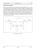
Hydraulic Operation
The operation of a typical hydraulic system is illustrated in Figure 8. Oil from a tank or
reservoir flows through a pipe into a pump. Often a filter is provided on the pump suction to
remove impurities from the oil. The pump, usually a gear-type, positive displacement pump, can
be driven by an electric motor, air motor, gas or steam turbine, or an internal combustion engine.
The pump increases the pressure of the oil. The actual pressure developed depends upon the
design of the system.
Most hydraulic systems have some method of preventing overpressure. As seen in Figure 8, one
method of pressure control involves returning hydraulic oil to the oil reservoir. The pressure
control box shown on Figure 8 is usually a relief valve that provides a means of returning oil to
the reservoir upon overpressurization.
Rev. 0 ME-05
Page 11
HYDRAULICS DOE-HDBK-1018/2-93 Miscellaneous Mechanical Components
The high pressure oil flows through a control valve (directional control). The control valve
Figure 8 Basic Hydraulic System
changes the direction of oil flow, depending upon the desired direction of the load. In Figure
8 the load can be moved to the left or to the right by changing the side of the piston to which
the oil pressure is applied. The oil that enters the cylinder applies pressure over the area of the
piston, developing a force on the piston rod. The force on the piston rod enables the movement
of a load or device. The oil from the other side of the piston returns to a reservoir or tank.
Hazards
The hazards and precautions listed in the previous chapter on air compressors are applicable to
hydraulic systems as well, because most of the hazards are associated with high pressure
conditions. Any use of a pressurized medium can be dangerous. Hydraulic systems carry all the
hazards of pressurized systems and special hazards that are related directly to the composition
of the fluid used.
ME-05 Rev. 0
Page 12
Miscellaneous Mechanical Components DOE-HDBK-1018/2-93 HYDRAULICS
When using oil as a fluid in a high pressure hydraulic system, the possibility of fire or an
explosion exists. A severe fire hazard is generated when a break in the high pressure piping
occurs and the oil is vaporized into the atmosphere. Extra precautions against fire should be
practiced in these areas.
If oil is pressurized by compressed air, an explosive hazard exists if the high pressure air comes
into contact with the oil, because it may create a diesel effect and subsequent explosion. A
carefully followed preventive maintenance plan is the best precaution against explosion.
Summary
The important information in this chapter is summarized below.
Hydraulics Summary
The relationship between pressure and force in a hydraulic piston
is expressed mathematically as:
F= P x A
where:
F = force
P = pressure
A = area
Oil from a tank or reservoir flows through a pipe into a pump. The
pump can be driven by a motor, turbine, or an engine. The pump
increases the pressure of the oil.
The high pressure oil flows in the piping through a control valve. The
control valve changes the direction of the oil flow. A relief valve, set at
a desired safe operating pressure, protects the system from an over-
pressure condition. Oil entering the cylinder applies pressure to the
piston, developing a force on the piston rod.
The force on the piston rod enables the movement of a load or device.
The oil from the other side of the piston returns to a reservoir or tank
via a filter, which removes foreign particles.
Rev. 0 ME-05
Page 13
BOILERS DOE-HDBK-1018/2-93 Miscellaneous Mechanical Components
BOILERS
Boilers are commonly used at large facilities to act as primary or backup steam
sources. The source of heat that generates the steam varies, but the basic
operation of the boiler is the same. This chapter will summarize the operation
of a boiler.
EO 1.7 DESCRIBE the basic operation of a boiler.
EO 1.8 IDENTIFY the following components of a typical boiler:
a. Steam drum d. Downcomer
b. Distribution header(s) e. Risers
c. Combustion chamber
Introduction
The primary function of a boiler is to produce steam at a given pressure and temperature. To
accomplish this, the boiler serves as a furnace where air is mixed with fuel in a controlled
combustion process to release large quantities of heat. The pressure-tight construction of a
boiler provides a means to absorb the heat from the combustion and transfer this heat to raise
water to a temperature such that the steam produced is of sufficient temperature and quality
(moisture content) for steam loads.
Boilers
Two distinct heat sources used for boilers are electric probes and burned fuel (oil, coal, etc.)
This chapter will use fuel boilers to illustrate the typical design of boilers. Refer to Figure 9
during the following discussion.
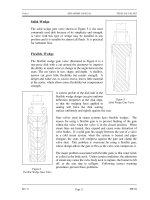
The boiler has an enclosed space where the fuel combustion takes place, usually referred to as
the furnace or combustion chamber. Air is supplied to combine with the fuel, resulting in
combustion. The heat of combustion is absorbed by the water in the risers or circulating tubes.
The density difference between hot and cold water is the driving force to circulate the water
back to the steam drum. Eventually the water will absorb sufficient heat to produce steam.
Steam leaves the steam drum via a baffle, which causes any water droplets being carried by the
steam to drop out and drain back to the steam drum. If superheated steam is required, the steam
may then travel through a superheater. The hot combustion gasses from the furnace will heat
the steam through the superheater's thin tube walls. The steam then goes to the steam supply
system and the various steam loads.
ME-05 Rev. 0
Page 14
Miscellaneous Mechanical Components DOE-HDBK-1018/2-93 BOILERS
Some boilers have economizers to improve cycle efficiency by preheating inlet feedwater to the
boiler. The economizer uses heat from the boiler exhaust gasses to raise the temperature of the
inlet feedwater.
Figure 9 Typical Fuel Boiler
Rev. 0 ME-05
Page 15
BOILERS DOE-HDBK-1018/2-93 Miscellaneous Mechanical Components
Fuel Boiler Components
Figure 9 illustrates a typical fuel boiler. Some of the components are explained below.
Steam drum - The steam drum separates the steam from the heated water. The
water droplets fall to the bottom of the tank to be cycled again,
and the steam leaves the drum and enters the steam system.
Feedwater enters at the bottom of the drum to start the heating
cycle.
Downcomers - Downcomers are the pipes in which the water from the steam
drum travels in order to reach the bottom of the boiler where the
water can enter the distribution headers.
Distribution headers - The distribution headers are large pipe headers that carry the
water from the downcomers to the risers.
Risers - The piping or tubes that form the combustion chamber enclosure
are called risers. Water and steam run through these to be
heated. The term risers refers to the fact that the water flow
direction is from the bottom to the top of the boiler. From the
risers, the water and steam enter the steam drum and the cycle
starts again.
Combustion chamber - Located at the bottom of a boiler, the combustion chamber is
where the air and fuel mix and burn. It is lined with the risers.
ME-05 Rev. 0
Page 16
Miscellaneous Mechanical Components DOE-HDBK-1018/2-93 BOILERS
Summary
The important information in this chapter is summarized below.
Boilers Summary
Boilers are vessels that allow water in contained piping to be heated to steam
by a heat source internal to the vessel. The water is heated to the boiling
point. The resulting steam separates, and the water is heated again. Some
boilers use the heat from combustion off-gasses to further heat the steam
(superheat) and/or to preheat the feedwater.
The following components were discussed:
The steam drum is where the steam is separated from the heated water.
Downcomers are the pipes in which the water from the steam drum travels to
reach the bottom of the boiler.
Distribution headers are large pipe headers that carry the water from the
downcomers to the risers.
Risers are the piping or tubes that form the combustion chamber enclosure.
Water and steam run through the risers to be heated.
The combustion chamber is located at the bottom of the boiler and is where
the air and fuel mix and burn.
Rev. 0 ME-05
Page 17
COOLING TOWERS DOE-HDBK-1018/2-93 Miscellaneous Mechanical Components
COOLING TOWERS
In an effort to lower costs and meet new environmental regulations, companies are
developing new ways to do things. One of the developments which meets both
cost decrease and environmental awareness is the cooling tower. This chapter will
summarize the advantages of cooling towers and how they function.
EO 1.9 STATE the purpose of cooling towers.
EO 1.10 DESCRIBE the operation of the following types of cooling
towers:
a. Forced draft
b. Natural convection
Purpose
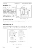
Before the development of cooling towers, rivers, lakes, and cooling ponds were required to
supply cooling. Through the development of the mechanical draft cooling tower, as little as one
square foot of area is needed for every 1000 square feet required for a cooling pond or lake.
Cooling towers minimize the thermal pollution of the natural water heat sinks and allow the
reuse of circulating water. An example of the manner in which a cooling tower can fit into a
system is shown in Figure 10.
Figure 10 Cooling System Containing Cooling Tower
ME-05 Rev. 0
Page 18
Miscellaneous Mechanical Components DOE-HDBK-1018/2-93 COOLING TOWERS
The cooling of the water in a cooling tower is accomplished by the direct contact of water and
air. This cooling effect is provided primarily by an exchange of latent heat of vaporization
resulting from evaporation of a small amount of water and by a transfer of sensible heat, which
raises the temperature of the air. The heat transferred from the water to the air is dissipated to
the atmosphere.
Induced Draft Cooling Towers
Induced draft cooling towers, illustrated in Figure 11, are constructed such that the incoming
circulating water is dispersed throughout the cooling tower via a spray header. The spray is
directed down over baffles that are designed to maximize the contact between water and air. The
air is drawn through the baffled area by large circulating fans and causes the evaporation and
the cooling of the water.
Figure 11 Induced Draft Cooling Tower
Rev. 0 ME-05
Page 19
COOLING TOWERS DOE-HDBK-1018/2-93 Miscellaneous Mechanical Components
The nomenclature for induced draft cooling towers, including some items not illustrated in
Figure 11 is summarized below.
Casing - The casing encloses the walls of the cooling tower, exclusive of
fan deck and louvers.
Collecting basin - The collecting basin is a receptacle beneath the cooling tower
for collecting the water cooled by the cooling tower. It can be
made of concrete, wood, metal, or an alternative material.
Certain necessary accessories are required such as sump,
strainers, overflow, drain, and a makeup system.
Drift eliminators - The drift eliminators are parallel blades of PVC, wood, metal,
or an alternative material arranged on the air discharge side of
the fill to remove entrained water droplets from the leaving air
stream.
Driver - The driver is a device that supplies power to turn the fan. It is
usually an electric motor, but turbines and internal combustion
engines are occasionally used.
Drive shaft - The drive shaft is a device, including couplings, which
transmits power from the driver to the speed reducer.
Fan - The fan is a device used to induce air flow through the cooling
tower.
Fan deck - The fan deck is a horizontal surface enclosing the top of the
cooling tower above the plenum that serves as a working
platform for inspection and maintenance.
Fan stack - The fan stack is a cylinder enclosing the fan, usually with an
eased inlet and an expanding discharge for increased fan
efficiency.
Fill - The fill is PVC, wood, metal, or an alternative material that
provides extended water surface exposure for evaporative heat
transfer.
Intake louvers - The intake louvers are an arrangement of horizontal blades at
the air inlets that prevent escape of falling water while allowing
the entry of air.
ME-05 Rev. 0
Page 20
Miscellaneous Mechanical Components DOE-HDBK-1018/2-93 COOLING TOWERS
Makeup valve - The makeup valve is a valve that introduces fresh water into the
collection basin to maintain the desired collecting basin water
level.
Overflow - The overflow is a drain that prevents the collecting basin from
overflowing.
Partition - The partition is a baffle within a multicell cooling tower that is
used to prevent air and/or water flow between adjacent cells.
Plenum - The plenum is the internal cooling tower area between the drift
eliminators and the fans.
Speed reducer - The speed reducer is a right-angle gear box that transmits
power to the fan while reducing the driver speed to that
required for optimal fan performance.
Sump - The sump is a depressed portion of the collecting basin from
which cold water is drawn to be returned to the connected
system. The sump usually contains strainer screens, antivortex
devices, and a drain or cleanout connection.
Distribution system - The distribution system is that portion of a cooling tower that
distributes water over the fill area. It usually consists of one or
more flanged inlets, flow control valves, internal headers,
distribution basins, spray branches, metering orifices, and other
related components.
Forced Draft Cooling Towers
Forced draft cooling towers are very similar to induced draft cooling towers. The primary
difference is that the air is blown in at the bottom of the tower and exits at the top. Forced draft
cooling towers are the forerunner to induced draft cooling towers. Water distribution problems
and recirculation difficulties discourage the use of forced draft cooling towers.
Natural Convection Cooling Towers
Natural convection cooling towers, illustrated in Figure 12, use the principle of convective flow
to provide air circulation. As the air inside the tower is heated, it rises through the tower. This
process draws more air in, creating a natural air flow to provide cooling of the water. The basin
at the bottom of the tower is open to the atmosphere. The cooler, more dense air outside the
Rev. 0 ME-05
Page 21
COOLING TOWERS DOE-HDBK-1018/2-93 Miscellaneous Mechanical Components
tower will flow in at the bottom and contribute to the air circulation within the tower. The air
circulation will be self perpetuating due to the density difference between the warmer air inside
and the cooler air outside.
Figure 12 Natural Convection Cooling Tower
The incoming water is sprayed around the circumference of the tower and cascades to the
bottom. The natural convection cooling towers are much larger than the forced draft cooling
towers and cost much more to construct. Because of space considerations and cost, natural
convection cooling towers are built less frequently than other types.
ME-05 Rev. 0
Page 22