Mechanical Science HandbooksMechanical Science Handbooks 10000 Part 10 docx
Bạn đang xem bản rút gọn của tài liệu. Xem và tải ngay bản đầy đủ của tài liệu tại đây (362.5 KB, 10 trang )
Pumps DOE-HDBK-1018/1-93 LIST OF TABLES
LIST OF TABLES
None
Rev. 0 ME-03
Page iii
REFERENCES DOE-HDBK-1018/1-93 Pumps
REFERENCES
Babcock & Wilcox, Steam, Its Generations and Use, Babcock & Wilcox Co.
Cheremisinoff, N. P., Fluid Flow, Pumps, Pipes and Channels, Ann Arbor Science.
General Physics, Heat Transfer, Thermodynamics and Fluid Flow Fundamentals, General
Physics Corporation.
Academic Program for Nuclear Power Plant Personnel, Volume III, Columbia, MD,
General Physics Corporation, Library of Congress Card #A 326517, 1982.
Stewart, Harry L., Pneumatics & Hydraulics, Theodore Audel & Company.
ME-03 Rev. 0
Page iv
Pumps DOE-HDBK-1018/1-93 OBJECTIVES
TERMINAL OBJECTIVE
1.0 Without references, DESCRIBE the purpose, construction, and principles of operation for
centrifugal pumps.
ENABLING OBJECTIVES
1.1 STATE the purposes of the following centrifugal pump components:
a. Impeller
b. Volute
c. Diffuser
d. Packing
e. Lantern Ring
f. Wearing ring
1.2 Given a drawing of a centrifugal pump, IDENTIFY the following major
components:
a. Pump casing
b. Pump shaft
c. Impeller
d. Volute
e. Stuffing box
f. Stuffing box gland
g. Packing
h. Lantern Ring
i. Impeller wearing ring
j. Pump casing wearing ring
1.3 DEFINE the following terms:
a. Net Positive Suction Head Available
b. Cavitation
c. Gas binding
d. Shutoff head
e. Pump runout
1.4 STATE the relationship between net positive suction head available and net positive
suction head required that is necessary to avoid cavitation.
1.5 LIST three indications that a centrifugal pump may be cavitating.
1.6 LIST five changes that can be made in a pump or its surrounding system that can reduce
cavitation.
1.7 LIST three effects of cavitation.
1.8 DESCRIBE the shape of the characteristic curve for a centrifugal pump.
1.9 DESCRIBE how centrifugal pumps are protected from the conditions of dead heading
and pump runout.
Rev. 0 ME-03
Page v
OBJECTIVES DOE-HDBK-1018/1-93 Pumps
TERMINAL OBJECTIVE
2.0 Without references, DESCRIBE the purpose, construction, and principle of operation for
positive displacement pumps.
ENABLING OBJECTIVES
2.1 STATE the difference between the flow characteristics of centrifugal and positive
displacement pumps.
2.2 Given a simplified drawing of a positive displacement pump, CLASSIFY the pump as
one of the following:
a. Reciprocating piston pump
b. Gear-type rotary pump
c. Screw-type rotary pump
d. Lobe-type rotary pump
e. Moving vane pump
f. Diaphragm pump
2.3 EXPLAIN the importance of viscosity as it relates to the operation of a reciprocating
positive displacement pump.
2.4 DESCRIBE the characteristic curve for a positive displacement pump.
2.5 DEFINE the term slippage.
2.6 STATE how positive displacement pumps are protected against overpressurization.
ME-03 Rev. 0
Page vi
Pumps DOE-HDBK-1018/1-93 CENTRIFUGAL PUMPS
CENTRIFUGAL PUMPS
Centrifugal pumps are the most common type of pumps found in DOE facilities.
Centrifugal pumps enjoy widespread application partly due to their ability to
operate over a wide range of flow rates and pump heads.
EO 1.1 STATE the purposes of the following centrifugal pump
components:
a. Impeller
b. Volute
c. Diffuser
d. Packing
e. Lantern Ring
f. Wearing ring
EO 1.2 Given a drawing of a centrifugal pump, IDENTIFY the
following major components:
a. Pump casing
b. Pump shaft
c. Impeller
d. Volute
e. Stuffing box
f. Stuffing box gland
g. Packing
h. Lantern Ring
i. Impeller wearing ring
j. Pump casing wearing ring
Introduction
Centrifugal pumps basically consist of a stationary pump casing and an impeller mounted on a
rotating shaft. The pump casing provides a pressure boundary for the pump and contains
channels to properly direct the suction and discharge flow. The pump casing has suction and
discharge penetrations for the main flow path of the pump and normally has small drain and vent
fittings to remove gases trapped in the pump casing or to drain the pump casing for maintenance.
Figure 1 is a simplified diagram of a typical centrifugal pump that shows the relative locations
of the pump suction, impeller, volute, and discharge. The pump casing guides the liquid from
the suction connection to the center, or eye, of the impeller. The vanes of the rotating impeller
impart a radial and rotary motion to the liquid, forcing it to the outer periphery of the pump
casing where it is collected in the outer part of the pump casing called the volute. The volute
is a region that expands in cross-sectional area as it wraps around the pump casing. The purpose
of the volute is to collect the liquid discharged from the periphery of the impeller at high
velocity and gradually cause a reduction in fluid velocity by increasing the flow area. This
converts the velocity head to static pressure. The fluid is then discharged from the pump
through the discharge connection.
Rev. 0 ME-03
Page 1
CENTRIFUGAL PUMPS DOE-HDBK-1018/1-93 Pumps
Figure 1 Centrifugal Pump
Centrifugal pumps can also be constructed in a manner that results in two distinct volutes, each
receiving the liquid that is discharged from a 180
o
region of the impeller at any given time.
Pumps of this type are called double volute pumps (they may also be referred to a split volute
pumps). In some applications the double volute minimizes radial forces imparted to the shaft and
bearings due to imbalances in the pressure around the impeller. A comparison of single and
double volute centrifugal pumps is shown on Figure 2.
Figure 2 Single and Double Volutes
ME-03 Rev. 0
Page 2
Pumps DOE-HDBK-1018/1-93 CENTRIFUGAL PUMPS
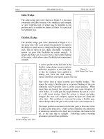
Diffuser
Figure 3 Centrifugal Pump Diffuser
Some centrifugal pumps contain
diffusers. A diffuser is a set of
stationary vanes that surround the
impeller. The purpose of the
diffuser is to increase the
efficiency of the centrifugal pump
by allowing a more gradual
expansion and less turbulent area
for the liquid to reduce in velocity.
The diffuser vanes are designed in
a manner that the liquid exiting the
impeller will encounter an ever-
increasing flow area as it passes
through the diffuser. This increase
in flow area causes a reduction in
flow velocity, converting kinetic
energy into flow pressure.
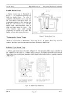
Impeller Classification
Impellers of pumps are classified
Figure 4 Single-Suction and Double-Suction Impellers
based on the number of points that
the liquid can enter the impeller
and also on the amount of
webbing between the impeller
blades.
Impellers can be either single-
suction or double-suction. A
single-suction impeller allows
liquid to enter the center of the
blades from only one direction. A
double-suction impeller allows
liquid to enter the center of the
impeller blades from both sides
simultaneously. Figure 4 shows
simplified diagrams of single and
double-suction impellers.
Rev. 0 ME-03
Page 3
CENTRIFUGAL PUMPS DOE-HDBK-1018/1-93 Pumps
Impellers can be open, semi-open, or enclosed. The open impeller consists only of blades
attached to a hub. The semi-open impeller is constructed with a circular plate (the web) attached
to one side of the blades. The enclosed impeller has circular plates attached to both sides of the
blades. Enclosed impellers are also referred to as shrouded impellers. Figure 5 illustrates
examples of open, semi-open, and enclosed impellers.
Figure 5 Open, Semi-Open, and Enclosed Impellers
The impeller sometimes contains balancing holes that connect the space around the hub to the
suction side of the impeller. The balancing holes have a total cross-sectional area that is
considerably greater than the cross-sectional area of the annular space between the wearing ring
and the hub. The result is suction pressure on both sides of the impeller hub, which maintains
a hydraulic balance of axial thrust.
Centrifugal Pump Classification by Flow
Centrifugal pumps can be classified based on the manner in which fluid flows through the pump.
The manner in which fluid flows through the pump is determined by the design of the pump
casing and the impeller. The three types of flow through a centrifugal pump are radial flow, axial
flow, and mixed flow.
Radial Flow Pumps
In a radial flow pump, the liquid enters at the center of the impeller and is directed out
along the impeller blades in a direction at right angles to the pump shaft. The impeller
of a typical radial flow pump and the flow through a radial flow pump are shown in
Figure 6.
ME-03 Rev. 0
Page 4
Pumps DOE-HDBK-1018/1-93 CENTRIFUGAL PUMPS
Axial Flow Pumps
Figure 6 Radial Flow Centrifugal Pump
In an axial flow pump, the impeller pushes the liquid in a direction parallel to the pump
shaft. Axial flow pumps are sometimes called propeller pumps because they operate
essentially the same as the propeller of a boat. The impeller of a typical axial flow pump
and the flow through a radial flow pump are shown in Figure 7.
Figure 7 Axial Flow Centrifugal Pump
Rev. 0 ME-03
Page 5
CENTRIFUGAL PUMPS DOE-HDBK-1018/1-93 Pumps
Mixed Flow Pumps
Mixed flow pumps borrow characteristics from both radial flow and axial flow pumps.
As liquid flows through the impeller of a mixed flow pump, the impeller blades push the
liquid out away from the pump shaft and to the pump suction at an angle greater than
90
o
. The impeller of a typical mixed flow pump and the flow through a mixed flow
pump are shown in Figure 8.
Figure 8 Mixed Flow Centrifugal Pump
Multi-Stage Centrifugal Pumps
A centrifugal pump with a single impeller that can develop a differential pressure of more than
150 psid between the suction and the discharge is difficult and costly to design and construct.
A more economical approach to developing high pressures with a single centrifugal pump is to
include multiple impellers on a common shaft within the same pump casing. Internal channels
in the pump casing route the discharge of one impeller to the suction of another impeller.
Figure 9 shows a diagram of the arrangement of the impellers of a four-stage pump. The water
enters the pump from the top left and passes through each of the four impellers in series, going
from left to right. The water goes from the volute surrounding the discharge of one impeller to
the suction of the next impeller.
A pump stage is defined as that portion of a centrifugal pump consisting of one impeller and its
associated components. Most centrifugal pumps are single-stage pumps, containing only one
impeller. A pump containing seven impellers within a single casing would be referred to as a
seven-stage pump or, or generally, as a multi-stage pump.
ME-03 Rev. 0
Page 6