Bearing Design in Machinery Episode 3 Part 7 docx
Bạn đang xem bản rút gọn của tài liệu. Xem và tải ngay bản đầy đủ của tài liệu tại đây (422.64 KB, 15 trang )
Although these testing machines are useful for evaluating the performance
of solid lubricants and comparing bearing materials for dry friction, there are
serious reservations concerning the testing accuracy of liquid lubricants for
boundary friction or comparing various boundary friction lubricant additives.
These reservations concern the basic assumption of boundary lubrication tests:
that there is only one boundary lubrication friction coefficient, independent of
sliding speed, that can be compared for different lubricants. However, measure-
ments indicated that, in many cases, the friction coefficient is very sensitive to the
viscosity or sliding speed. For example, certain additives can increase the
viscosity, which will result in higher hydrodynamic load capacity and, in turn,
reduction of the boundary friction.
The friction force has a hydrodynamic component in addition to the contact
friction (adhesion friction). Therefore, it is impossible to completely separate the
magnitude of the two friction components. Certain boundary additives to mineral
oils may reduce the friction coefficient, only because they slightly increase the
viscosity. Even for line or point contact, there is an EHD effect that increases with
velocity and sliding speed. The hydrodynamic effect would reduce the boundary
friction because it generates a thin film that separates the surfaces. This argument
has practical consequences on the testing of boundary layer lubricants. These
FIG. 14-1 Friction and wear tests of nonconformal contacts.
Copyright 2003 by Marcel Dekker, Inc. All Rights Reserved.
tests are intended to measure only the adhesion friction of boundary lubrication;
however, there is an additional viscous component.
Currently, boundary lubricants are evaluated by measuring the friction at an
arbitrary constant sliding speed (e.g., four-ball tester operating at constant speed).
The current testing methods of liquid boundary lubricants should be reevaluated.
Apparently, better tests would be obtained by measuring the complete friction
versus velocity, f-U, curve. In Sections 14.6 and 14.7, dynamic testing machines
are described that are better able to evaluate separately the contact friction at the
start-up and the mixed and hydrodynamic friction. The friction is a function of
speed, which can be measured by dynamic tests.
14.3 FRICTION TESTING UNDER HIGH-
FREQUENCY OSCILLATIONS
It has already been mentioned that in real machines the contact stresses of mating
parts in relative motion are not completely constant. There are always vibrations
and time-variable conditions. Even when the load is constant, there are friction-
induced vibrations, resulting in small high-frequency oscillations in the tangential
direction (parallel to the surface). For these reasons, it was realized that testing
machines with high-frequency oscillations would offer a better simulation of the
actual conditions in machinery.
It is well known that rolling-element bearings operate under high-frequency
oscillations, and there has been a need for testing machines that simulate these
dynamic conditions. Tests under high-frequency oscillations have been adopted
as standard tests, such as ASTM D 5706 EP and ASTM D 5707 EP for greases
and oils for rolling bearings.
In the testing machine shown in Fig. 14-2, there is friction between the
upper specimen and the lower disk. The upper specimen can be a ball or a
cylinder, for point or line contact, or a ring, for area contact. The material and size
can be adapted to the user’s requirement (equivalent to the material used in the
actual machine). During the friction test, the upper specimen has horizontal
oscillations (parallel to the disk area). Force is applied mechanically to the upper
specimen in a vertical direction (normal to the disk area). The friction force is
measured by a piezoelectric sensor that is placed under the lower specimen
holder. The friction coefficient is calculated and recorded on-line on a chart
during the test. The environment in the test chamber (temperature and humidity)
can be controlled.
This test has been adopted by the American Society of Testing Materials
(ASTM) for testing greases or liquid lubricants operating under high contact
pressure, such as point or line contact in rolling bearings and gears. The
Copyright 2003 by Marcel Dekker, Inc. All Rights Reserved.
FIG. 14-3 Wear scars after a standard vibratory friction and wear test (from SRV Catalogue, with permission from
Optimal Instruments).
Copyright 2003 by Marcel Dekker, Inc. All Rights Reserved.
FIG. 14-4 Friction coefficient versus time (from SRV Catalogue, with permission from Optimal Instruments).
Copyright 2003 by Marcel Dekker, Inc. All Rights Reserved.
In Fig. 14-4, a test result is shown for a steel ball on a steel plate lubricated
by synthetic oil. The result is a curve of friction coefficient versus time. The test
time is 2 hours and the specimens are 10-mm steel balls on a lapped steel disk at
a temperature of 200
C. The frequency of horizontal oscillations is 50 Hz and
1.5-mm amplitude. The reported friction coefficients are f
min
¼0.1 and
f
max
¼0.14. The maximum wear measured during the test is 21 mm. The wear
scars after the test on the disk and ball are shown in Fig. 14-3.
The reservations that have been raised for the steady tests are still valid for
this vibratory test. Although these dynamic tests are effective in simulating the
overall performance of real machines, a problem with the high-frequency test is
that it does not test the pure effect of lubricant additives, such as antifriction and
antiwear additives. The friction and wear are the combined effect of the viscosity
of the lubricant as well as of the additives. In other words, there is no way to
distinguish between the hydrodynamic and adhesion friction effects. Therefore,
this would not be a good method to compare the effectiveness of various
boundary lubrication additives.
In Sec. 14.4, a testing machine is described for testing the complete
Stribeck curve. It offers a better distinction of the contact and viscous friction
and the friction at each region. Therefore, the Stribeck curve can be a more useful
test in developing and selecting lubricants. Nevertheless, the foregoing high-
frequency test is very useful in testing solid lubricants and greases. For liquid
lubricants, the test is useful for evaluating the combined effect under identical
conditions of a specific application in the field.
14.4 MEASUREMENT OF JOURNAL BEARING
FRICTION
The purpose of friction-testing machines is to measure the friction torque of a
journal test-bearing friction or rolling-element test-bearing friction in isolation
from any other source of friction in the system. There are several methods by
which to measure the friction in bearings. The first method is based on the
concept of the hydrostatic pad. It is designed for measuring the friction torque on
the bearing housing by a load cell, while the bearing load is transferred to the
bearing housing through a hydrostatic pad. Friction-testing machines with a
hydrostatic pad can be designed for the measurement of static or dynamic
friction. Dynamic friction is under time-variable conditions, such as oscillating
velocity and time-variable load. Dynamic friction measurements require contin-
uous recording or on-line data acquisition by a computer. All friction-testing
machines for dynamic friction are universal, in the sense that they can be used
under steady conditions as well as dynamic conditions. In most cases, however,
machines for testing steady friction cannot be adapted for dynamic friction.
Copyright 2003 by Marcel Dekker, Inc. All Rights Reserved.
A relatively simple friction-testing machine is the pendulum tester. It can be
applied for testing the friction coefficient of a journal bearing under steady
conditions only.
The concept of this pendulum friction tester is to apply a load on the
bearing by means of weight. The weights are placed on a rod connected to the
bearing. During a steady operation under constant speed, the pendulum is tilted to
an angle equal to the friction coefficient. An example of a pendulum tester is
shown in Fig. 14-5. The angle is small, and the angle is measured by a dial gauge
as shown.
This is a simple and low-cost tester. However, it has relatively low
measurement precision in comparison to other machines. There are always
small vibrations of the pendulum that make it difficult to get an average reading.
This can be improved by damping the vibrations via a viscous damper. A second
drawback that reduces the precision is that there is always some friction and it is
FIG. 14-5 Pendulum-type friction tester for a journal bearing.
Copyright 2003 by Marcel Dekker, Inc. All Rights Reserved.
impossible to adjust the zero position of the pendulum. A solution to this problem
is to test in the two directions; namely, for each measurement the shaft is rotating
in two directions. The pendulum-swing angle is measured for each direction and
the average calculated. This is a relatively time-consuming test.
This tester is limited to friction measurements under steady speed. A
variable-speed motor is used for measuring the f–U (friction versus velocity)
curve. However, each point in this curve is measured under steady-state condi-
tions. Since this tester is not for high-precision measurement, it is not suitable for
comparing lubricants where the difference in friction is expected to be within a
few percentage points.
14.5 TESTING OF DYNAMIC FRICTION
Most of the commercially available friction-testing machines have been designed
for measurements under steady conditions. For the measurement of dynamic
friction, under time-variable conditions, a unique design of the testing equipment,
with strict requirements, is called for. In addition to a rigid design, on-line
recording of the data and its processing is essential for time-variable conditions.
The most important principles in dynamic friction measurement are as
follows.
1. The machine as well as the support for the test bearing must be very
rigid. In addition, the load cell for measuring the friction force must be
as rigid as possible.
2. Relative sliding is obtained by means of a stationary part and a moving
part. The load cell for the friction measurement must always be
connected to the stationary side. If the load cell were to be connected
to the moving part, it would not read the correct friction force because
it would read inertial forces as friction force, and the result would be a
combined reading of friction and inertial forces.
3. The design must provide for a clear method of separating the measured
friction in the test bearing from any other sources of friction in the
system.
4. The testing system must provide the means for accurate measurement
of the velocity and displacement of the sliding part relative to the
stationary part.
5. The system must provide the means for on-line recording of the friction
versus time and versus sliding velocity. This is currently done by a
computer with a data-acquisition system. In addition, there is a
requirement to measure friction versus a small displacement during
the start-up.
Copyright 2003 by Marcel Dekker, Inc. All Rights Reserved.
6. The system must include the means to control the desired time-
dependent sliding motion and load. This can be achieved by using a
computer with direct current output and an amplifier that controls a
servomotor for the required motions. The controller in the computer
includes the algorithm for the control of motion and velocity. The
motion and velocity are measured on-line to provide feedback to the
computer controller for precision motion.
If the support of the steady part is not sufficiently rigid (including the load
cell), there are several types of errors that are encountered in the measurements.
Under dynamic operation, the stationary part will have a small variable displace-
ment due to the elasticity in the system. This would result in reading errors in the
load cell because small inertial forces would be added to the friction reading. This
means that due to a variable elastic displacement there is a small acceleration, and
the load cell will read inertial forces as friction force.
Moreover, if the system were not rigid, there would be friction-induced
vibrations (stick-slip friction, see Sec. 16.1) at low velocity. In conclusion, the
dynamics of the system can affect the friction measurement, and we are interested
in a clean experiment where the bearing friction is measured in isolation from any
other effect.
The examples in the following sections are of several universal testing
machines for measuring rolling-element bearing friction or journal bearing
friction under dynamic conditions. Although other designs of friction-testing
machines are often used, all are based on similar concepts. The first two friction-
testing machines can be applied for a journal bearing or a rolling-element
bearing; the third machine is for friction in linear sliding motion.
14.6 FRICTION-TESTING MACHINE WITH A
HYDROSTATIC PAD
A friction-testing machine with hydrostatic pad is shown in Fig. 14-6. It has a
main shaft supported by two conical rolling bearings. The two bearings form an
adjustable arrangement to eliminate undesirable clearance in these bearings. The
shaft is driven by a variable-speed motor. In Fig. 14-6, the test bearing is a rolling-
element bearing on the right side of the shaft, but it can be a journal bearing as
well. The test bearing is housed in a cylindrical casing containing lubricant at a
constant level.
The main shaft ends with a cone, on which a conical bore sleeve is
mounted. The conical sleeve can by tightened by a nut, and in this way the outside
diameter of the sleeve is slightly varied by elastic deformation. The test bearing, a
journal bearing or rolling bearing, is mounted on this sleeve, and the clearance
Copyright 2003 by Marcel Dekker, Inc. All Rights Reserved.
This apparatus measures only the friction in the test bearing and not any
other source of friction, such as the two conical bearings that support the shaft.
This friction-testing machine is suitable for dynamic friction measurements as
well as friction under steady conditions. For more details of this testing machine,
see Lowey, Harnoy, and Bar-Nefi (1972).
The operation of this friction-testing machine under dynamic conditions
requires a servomotor controlled by a computer and data-acquisition system, as
described in Sections 14.7 and 14.8.
14.7 FOUR-BEARINGS MEASUREMENT
APPARATUS
An apparatus for dynamic friction measurement has been designed, developed,
and constructed in the bearing and lubrication laboratory of the Department of
Mechanical Engineering at the New Jersey Institute of Technology. This appa-
ratus can continuously measure the average dynamic friction of four equally
loaded sleeve bearings in isolation from any other source of friction in the system,
and the errors caused by inertial forces can be reduced to a negligible magnitude.
In Fig. 14-7 a cross section of the apparatus is shown, and a photograph is shown
in Fig. 14-8.
The design concept is to apply an internal load, action and reaction,
between the inner housing (N) and the outer housing (K) by tightening the nut
(P) on the bolt (R) to apply preload by deformation of the elastic steel ring (E).
There are four equal test sleeve bearings (H), two bearings inside each housing. In
this way, all four test bearings have approximately equal radial load, but in the
opposite direction for each two of the four bearings, due to the preload in the
elastic ring. The load on the bearings is measured by a calibrated, full strain gauge
bridge bonded to the elastic ring. The total friction torque of all four bearings is
measured by a calibrated rigid piezoelectric load cell, which prevents the rotation
of the outer bearing housing (K). The load is transferred to the load cell by a
radial arm attached to the external housing, as shown in the apparatus photograph
in Fig. 14-8. Thus, the measured friction torque of the four bearings is isolated
from any other sources of friction, such as friction in the ball bearings supporting
the shaft. The time-variable friction measured by the load cell is stored in a
computer with a data-acquisition system.
A lubricating oil reservoir is mounted above the mechanical apparatus in
order to supply oil by gravity into the four bearings through four segments of
flexible tubing. The oil is drained from the bearings through a hole in the external
housing into a collecting vessel.
The shaft (C) is supported by two ball bearings (A) attached to the main
support frame (B), and is driven by a computer-controlled DC servomotor. The
Copyright 2003 by Marcel Dekker, Inc. All Rights Reserved.
drive consists of a DC servomotor connected to the shaft through a timing belt
and two pulleys (D). The rotational speed of the shaft is measured by an encoder,
and this on-line measurement is fed into the computer, where the data is stored
and analyzed. This arrangement forms a closed-loop control of the rotation of the
shaft. In fact, the control algorithm includes a friction-compensation algorithm to
generate the precise sinusoidal velocity or any other desired periodic velocity.
It is interesting to note that the measurement principle of four bearings was
used by Mckee and Mckee as early as 1929. However, the early friction-testing
apparatus used sliding weights for measuring the friction torque; and of course,
this apparatus has been limited to bearings under steady conditions.
An improved version of the four-bearings friction-testing machine for
bearings that require self-aligning is shown in Fig. 14-9. The self-aligning
property is achieved by means of four self-aligning ball bearings. The self-
aligning bearings are held from rotating by thin metal strips. At the same time,
elastic bending of the strips allows a small angular rotation for self-aligning. In
addition, this design can easily be adapted for measurement of steady and
dynamic friction in rolling-element bearings.
FIG. 14-9 Friction-testing machine with self-alignment arrangement.
Copyright 2003 by Marcel Dekker, Inc. All Rights Reserved.
14.7.1 Measurement Error Under D ynamic
Conditions
It has already been mentioned that under dynamic conditions, there will always be
a small, unsteady angular rotation of the bearing housing and sleeve due to the
elasticity of its support (including elasticity of the load cell). This is the case in all
the testing machines, because there is always a certain elasticity in the system.
However, it is possible to minimize this elastic rotation of the bearing sleeve by a
rigid design of the frame of the machine and by using a rigid load cell. As a result
of this small angular elastic rotation of the housing, there will be a small angular
acceleration, and the load cell, which keeps the bearing housing from rotating,
has a small error because it reads inertial forces (or torque) as friction force.
For friction measurement under dynamic conditions, the magnitude of
measurement error due to inertial forces has been evaluated by Harnoy et al.
(1994). The condition for a negligible error is
o
2
(
k
h
I
h
ð14-1Þ
Here, k
h
is the angular stiffness of the bearing housing support, o is the freqency
of oscillations under dynamic conditions, such as periodic load, and I
h
is the
moment of inertia of the bearing housing together with the bearing sleeve.
Piezoelectric load cells are much more rigid than strain gage, beam-type
load-cells. However, for low-frequency tests, the piezoelectric cells have the
disadvantage of an output drift. At the same time, at low frequency, our error
analysis indicated that the elasticity of the load cell does not cause any significant
measurement error. This discussion indicates that best results can be achieved by
using a piezoelectric load cell for high-frequency tests and strain gage beam-type
load cells for low-frequency oscillations.
14.8 APPARATUS FOR MEASURING FRICTION
IN LINEAR MOTION
A cross-sectional view of the linear-motion friction measurement apparatus is
shown in Fig. 14-10. The apparatus comprises of a linear motion sliding table,
driven by a servomotor and a ball screw drive. A closed-loop control system is
provided via personal computer. Also, the computer system can store the
experimental data for analysis. For regular precision, the sliding motion is
measured by an encoder, which measures the rotation of the screw that drives
the table. For high-precision measurement of the linear motion, an LVDT motion
sensor can be used.
The design concept of the apparatus is a ball screw driven linear-position-
ing table (1), where the backlash can be eliminated, by preloading the screw drive.
Copyright 2003 by Marcel Dekker, Inc. All Rights Reserved.
FIG. 14-12 Isometric of a linear-motion friction-measurement apparatus.
Copyright 2003 by Marcel Dekker, Inc. All Rights Reserved.
This apparatus is designed for measuring friction at very low sliding speeds. This
is achieved by a speed reduction of considerable ratio by the screw drive. In
addition, the speed of the motor is reduced by a set of pulleys and a timing belt
(3-5). Closed-loop controlled motion is generated by a computer-controlled DC
servomotor (2). Precise measurements of the motion is fed into a computer, which
is equipped with a data-acquisition board.
In this linear apparatus, the contact geometry between the sliding surfaces
can be replaced. Enlargement of the sensing area is shown in Fig. 14-11. It can
test a sliding plane, a line or a point contact. The drawing shows a line contact
between a nonrotating cylindrical shaft and a flat plate. The contact can be made
of various material combinations. The line contact is created between a short,
finely ground cylindrical shaft (K) and the flat friction surface (N). The shaft (K)
is clamped in a housing assembly (I, J and H) designed to hold various shaft
diameters. The normal load is centered above the line contact, and is supplied by
a rod (P), which has weights attached (weights not shown). When the friction test
surface moves, the friction force is transmitted through the housing assembly to a
piezoelectric load cell. The load cell generates a voltage signal proportional to the
friction force magnitude, which is fed to a data-acquisition system in a computer.
The design is shown in the isometric view in Fig. 14-12. The friction
surface base (N) is attached to a moving platform (O) that is driven by the ball
screw drive. The friction contact area can be dipped in lubricant, since the base
has an attached railing (L and M), which serves to contain the lubricant.
For precise dynamic measurements, particularly with high-frequency oscil-
lations, the load cell must be rigid as well as the support of the load cell. This is
essential to prevent undesirable small linear displacement of the stationary
cylinder (due to elastic deformation of the load-cell system and the support
under the friction force). In the case of elastic displacement, the friction reading
may include a small error of inertial force, acting on the load-cell (this is the
major reason why most commercial friction testing devices are not suitable for
dynamic tests).
Results of dynamic friction measurements performed by the last two testing
machines are included in Chapter 17. The tests were conducted for oscillating
motion at various frequencies, and the results are in the form of dynamic f–U
curves.
Copyright 2003 by Marcel Dekker, Inc. All Rights Reserved.
15
Hydrodynamic Bearings Under
Dynamic Conditions
15.1 INTRODUCTION
Hydrodynamic journal bearings under steady conditions were discussed in the
previous chapters. The equations for pressure wave and load capacity were
limited to a constant, steady load and constant speed. Under steady conditions of
constant load and speed, the journal center is at a stationary point defined by a
constant eccentricity and attitude angle. Under dynamic conditions, however,
such as oscillating load or variable speed, the journal center moves relative to the
bearing.
Under harmonic oscillations such as sinusoidal load, the journal center
moves in a trajectory that repeats itself during each cycle. This type of trajectory
is referred to as journal center locus. In practice, bearings in machines are always
subjected to some dynamic conditions. In rotating machinery, there are always
vibrations due to the shaft imbalance. The machine is a dynamic system that has a
spectrum of vibration frequencies. Vibrations in a machine result in small
oscillating forces (inertial forces) on the bearings at various frequencies, which
are superimposed on the main, steady load. If the magnitude of the dynamic
forces is very small in comparison to the main, steady force, the dynamic forces
are disregarded.
However, there are many important cases where the dynamic bearing
performance is important and must be analyzed. For example, the effects of
Copyright 2003 by Marcel Dekker, Inc. All Rights Reserved.
bearing whirl near the critical speeds of the shaft can result in bearing failure.
Dynamic analysis must always be performed in critical applications where
bearing failure is expensive, such as the high cost of loss of production in
generators or steam turbines or where there are safety considerations. In these
cases, it is important for the design engineer to perform a dynamic analysis in
order to predict undesired dynamic effects and prevent them by appropriate
design.
In many machines the load is not steady. For example, the bearings in car
engines are subjected to a cycle of a variable force that results from the
combustion and inertial forces in the engine. There are many variable-speed
machines that involve unsteady bearing performance, and even machines that
operate at steady conditions are subjected to dynamic conditions during start-up
and stopping.
In fact, most bearing failures result from an unexpected dynamic effect,
such as a large vibration or severe disturbances. Engineers can improve the
resistance of hydrodynamic bearings to unexpected dynamic effects by compar-
ing the dynamic response of various bearing designs to scenarios of possible
disturbances. An example of a unique design that improves the dynamic response
is included in Chapter 18.
15.2 ANALYSIS OF SHORT BEARINGS UNDER
DYNAMIC CONDITIONS
The following is a dynamic analysis of a short bearing. Short bearings are widely
used in many applications under dynamic conditions, including car engines. The
dynamic analysis of a short bearing is relatively simple because the bearing load
can be expressed by a closed-form equation, as shown in Chapter 7. This analysis
can be extended to a finite-length bearing, but the computations are more
complex because the load capacity at each step must be determined by a
numerical procedure.
The objective of a dynamic analysis is to solve for the trajectory of the
journal center. The analysis involves the derivation of a set of differential
equations and their solution by a finite-difference method with the aid of a
computer program.
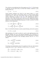
Dubois and Ocvirk (1953) solved the pressure distribution and load
capacity of a short journal bearing under a steady load (see Chapter 7). This
analysis is extended here to include unsteady conditions where the journal center,
O
1
, has an arbitrary velocity. It is shown in Fig. 15-1 that the journal center
velocity is described by two components, de=dt ¼ Cðde= dtÞ and e ðdf=dtÞ, in the
radial and tangential directions, respectively. The two assumptions of Dubois and
Ocvirk for a steady short bearing are maintained here for dynamic conditions.
Copyright 2003 by Marcel Dekker, Inc. All Rights Reserved.