Advanced Vehicle Technology Episode 1 Part 6 pdf
Bạn đang xem bản rút gọn của tài liệu. Xem và tải ngay bản đầy đủ của tài liệu tại đây (313.32 KB, 20 trang )
large planet gear absorbs the driving torque reaction
and in the process is made to revolve around the
braked sun gear. The overdrive condition is created
by the large planet gears being forced to roll `walk'
about the sun gear, while at the same time revolving
on their own axes. As a result, the small planet gears,
also revolving on the same carrier pins as the large
planet gears, drive forward the annular ring gear at a
faster speed relative to that of the input.
The overall gear ratio step up is achieved by
having two stages of meshing gear teeth; one
between the large pinion and sun gear and the
other between the small pinion and annulus ring
gear. By using this compound epicyclic gear train, a
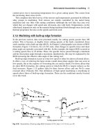
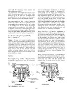
Fig. 3.30 Laycock double epicycle overdrive
92
relatively large step up gear ratio can be obtained
for a given diameter of annulus ring gear compared
to a single stage epicyclic gear train.
Direct drive (Fig. 3.30) Direct drive is attained by
releasing the double-sided cone clutch member from
the stationary conical brake and shifting it over so
that it contacts and engages the conical frictional
surface of the annulus ring gear. The power flow
from the input shaft and planet carrier now divides
into two paths Ð the small planet gear to annulus
ring gear route and the large planet gear, sun gear
and double-sided clutch member route, again finish-
ing up at the annulus ring gear. With such a closed
loop power flow arrangement, where the gears can-
not revolve independently to each other, the gears
jam so that the whole gear train combination rotates
as one about the input to output shaft axes. It
thereby provides a straight through direct drive. It
should be observed that the action of the unidirec-
tional roller clutch is similar to that described for the
single stage epicyclic overdrive.
Clutch operating (Fig. 3.30) Engagement of
direct drive and overdrive is achieved in a similar
manner to that explained under single stage epicyc-
lic overdrive unit.
Direct drive is provided by four powerful springs
holding the double-sided conical clutch member in
frictional contact with the annulus ring gear. Con-
versely, overdrive is obtained by a pair of hydraulic
slave pistons which overcome and compress the
clutch thrust springs, pulling the floating conical
clutch member away from the annulus and into
engagement with the stationary conical brake.
Hydraulic system (Fig. 3.30) Pressure supplied by
the hydraulic plunger type pump draws oil from the
sump and forces it past the non-return ball valve to
both the slave cylinders and to the solenoid valve
and the relief valve.
Direct drive engagement When direct drive is
engaged, the solenoid valve opens due to the sole-
noid being de-energized. Oil therefore flows not
only to the slave cylinders but also through the
solenoid ball valve to the overdrive lubrication sys-
tem where it then spills and returns to the sump. A
relatively low residual pressure will now be main-
tained within the hydraulic system. Should the oil
pressure rise due to high engine speed or blockage,
the low pressure ball valve will open and relieve the
excess pressure. Under these conditions the axial
load exerted by the clutch thrust springs will clamp
the double-sided floating conical clutch member to
the external conical shaped annulus ring gear.
Overdrive engagement To select overdrive the
solenoid is energized. This closes the solenoid ball
valve, preventing oil escaping via the lubrication
system back to the sump. Oil pressure will now
build up to about 26±30 bar, depending on vehicle
application, until sufficient thrust acts on both
slave pistons to compress the clutch thrust springs,
thereby permitting the double-sided clutch member
to shift over and engage the conical surface of the
stationary brake. To enable the engagement action
to overdrive to progress smoothly and to limit the
maximum hydraulic pressure, a high pressure valve
jumper is made to be pushed back and progres-
sively open. This controls and relieves the pressure
rise which would otherwise cause a rough, and
possibly sudden, clutch engagement.
3.8 Setting gear ratios
Matching the engine's performance characteristics
to suit a vehicle's operating requirements is pro-
vided by choosing a final drive gear reduction and
then selecting a range of gear ratios for maximum
performance in terms of the ability to climb gradi-
ents, achievement of good acceleration through the
gears and ability to reach some predetermined
maximum speed on a level road.
3.8.1 Setting top gear
To determine the maximum vehicle speed, the engine
brake power curve is superimposed onto the power
requirement curve which can be plotted from the
sum of both the rolling (R
r
)andair(R
a
)resistance
covering the entire vehicle's speed range (Fig. 3.31).
The total resistance R opposing motion at any
speed is given by:
R R
r
R
a
10C
r
W C
D
AV
2
where C
r
coefficient of rolling resistance
W gross vehicle weight (kg)
C
D
coefficient of aerodynamic resist-
ance (drag)
A projected frontal area of vehicle (m
2
)
V speed of vehicle (km/h)
93
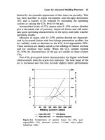
The top gear ratio is chosen so that the maxi-
mum road speed corresponds to the engine speed at
which maximum brake power is obtained (or just
beyond) (Fig. 3.32).
Gearing is necessary to ensure that the vehicle
speed is at a maximum when the engine is develop-
ing approximately peak power.
Thus
Linear wheel speed Linear road speed
dN
G
F
1000
60
V (m/min)
; Final drive gear ratio G
F
60 dN
100 V
0:06
dN
V
where G
F
final drive gear ratio
N engine speed (rev/min)
d effective wheel diameter (m)
V
road speed at which peak power is
developed (km/h)
Example A vehicle is to have a maximum road
speed of 150 km/h. If the engine develops its peak
power at 6000 rev/min and the effective road wheel
diameter is 0.54 m, determine the final drive gear ratio.
G
F
0:06 dN
V
0:06 Â 3:142 Â 0:54 Â 6000
150
4:07 X1
3.8.2 Setting bottom gear
The maximum payload and gradient the vehicle is
expected to haul and climb determines the necessary
tractive effort, and hence the required overall gear
ratio. The greatest gradient that is likely to be
encountered is decided by the terrain the vehicle is
to operate over. This normally means a maximum
gradientof5to1andintheextreme4to1.The
minimum tractive effort necessary to propel a vehicle
up the steepest slope may be assumed to be approxi-
mately equivalent to the sum of both the rolling and
gradient resistances opposing motion (Fig. 3.31).
The rolling resistance opposing motion may be
determined by the formula:
R
r
10C
r
W
where R
r
rolling resistance (N)
C
r
coefficient of rolling resistance
W gross vehicle weight (kg)
Average values for the coefficient of rolling
resistance for different types of vehicles travelling
at very slow speed over various surfaces have been
determined and are shown in Table 3.2.
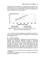
Likewise, the gradient resistance (Fig. 3.33)
opposing motion may be determined by the for-
mula:
R
g
10W
G
or 10W sin
where R
g
gradient resistance (N)
W gross vehicle weight (10W kg WN)
G gradient (1 in x) sin
Fig. 3.31 Forces opposing vehicle motion over its speed
range
Fig. 3.32 Relationship of power developed and road
power required over the vehicle's speed range
94
Tractive effort Resisting forces opposing motion
E R
R
r
R
g
(N)
where E tractive effort (N)
R resisting forces (N)
Once the minimum tractive effort has been cal-
culated, the bottom gear ratio can be derived in the
following way:
Driving torque Available torque
ER TG
B
G
F
M
; Bottom gear ratio G
B
ER
TG
F
M
where G
F
final drive gear ratio
G
B
bottom gear ratio
M
mechanical efficiency
E tractive effort (N)
T maximum engine torque (Nm)
R effective road wheel radius (m)
Example A vehicle weighing 1500 kg has a
coefficient of rolling resistance of 0.015. The trans-
mission has a final drive ratio 4.07:1 and an overall
mechanical efficiency of 85%.
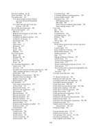
If the engine develops a maximum torque of
100 Nm (Fig. 3.34) and the effective road wheel
radius is 0.27 m, determine the gearbox bottom
gear ratio.
Assume the steepest gradient to be encountered
is a one in four.
R
r
10C
r
W
10 Â 0:015 Â 150 225N
R
g
10W
G
10 Â 1500
4
3750N
E R
r
R
g
3750 225 3975N
G
B
eR
TG
F
M
3975 Â 0:27
100 Â 4:07 Â 0:85
3:1X1
Fig. 3.33 Gradient resistance to motion
Fig. 3.34 Engine torque to speed characteristics
Table 3.2 Average values of coefficient of rolling
resistance
Coefficient of rolling resistance (C
r
)
Vehicle type
Concrete Medium hard soil Sand
Passenger Car 0.015 0.08 0.30
Trucks 0.012 0.06 0.25
Tractors 0.02 0.04 0.20
Note The coefficient of rolling resistance is the ratio of the
rolling resistance to the normal load on the tyre.
i:e: C
r
R
r
W
95
3.8.3 Setting intermediate gear ratios
Ratios between top and bottom gears should be
spaced in such a way that they will provide the
tractive effort±speed characteristics as close to the
ideal as possible. Intermediate ratios can be best
selected as a first approximation by using a geo-
metric progression. This method of obtaining the
gear ratios requires the engine to operate within the
same speed range in each gear, which is normally
selected to provide the best fuel economy.
Consider the engine to vehicle speed character-
istics for each gear ratio as shown (Fig. 3.35). When
changing gear the engine speed will drop from the
highest N
H
to the lowest N
L
without any change in
road speed, i.e. V
1
, V
2
, V
3
etc.
Let G
1
1st overall gear ratio
G
2
2nd overall gear ratio
G
3
3rd overall gear ratio
G
4
4th overall gear ratio
G
5
5th overall gear ratio
where Overall
gear ratio
Engine speed (rev/min)
Road wheel speed (rev/min)
Wheel speed when engine is on the high limit N
H
in
first gear G
1
N
H
G
1
(rev/min)
Wheel speed when engine is on the low limit N
L
in
second gear G
2
N
L
G
2
(rev/min)
These wheel speeds must be equal for true rolling
Hence
N
H
G
1
N
L
G
2
; G
2
G
1
N
L
N
H
Also
N
H
G
2
N
L
G
3
; G
3
G
2
N
L
N
H
and
N
H
G
3
N
L
G
4
; G
4
G
3
N
L
N
H
N
H
G
4
N
L
G
5
; G
5
G
4
N
L
N
H
The ratio
N
L
N
H
is known as the minimum to max-
imum speed range ratio K for a given engine.
Now, gear G
2
G
1
N
L
N
H
G
1
K,
since
N
L
N
H
k (a constant)
gear G
3
G
2
N
L
N
H
G
2
K (G
1
K)K
G
1
K
2
gear G
4
G
3
N
L
N
H
G
3
K (G
1
K
2
)K
G
1
K
3
gear G
5
G
4
N
L
N
H
G
4
K (G
1
K
3
)K
G
1
K
4
:
Hence the ratios form a geometric progression.
Fig. 3.35 Gear ratios selected on geometric progression
96
The following relationship will also apply for a
five speed gearbox:
G
2
G
1
G
3
G
2
G
4
G
3
G
5
G
4
N
L
N
H
K
and G
5
G
1
K
4
or K
4
G
5
G
1
Hence K
G
5
G
1
1
4
or
G
5
G
1
4
r
In general, if the ratio of the highest gear (G
T
)
and that of the lowest gear (G
B
) have been deter-
mined, and the number of speeds (gear ratios) of
the gearbox n
G
is known, the constant K can be
determined by:
K
G
T
G
B
1
nG
À1
So
G
T
G
B
K
nG
1
; G
T
G
B
K
nG
À1
For commercial vehicles, the gear ratios in
the gearbox are often arranged in geometric
progression. For passenger cars, to suit the chan-
ging traffic conditions, the step between the ratios
of the upper two gears is often closer than that
based on geometric progression. As a result, this
will affect the selection of the lower gears to some
extent.
Example A transmission system for a vehicle
is to have an overall bottom and top gear ratio
of 20:1 and 4.8 respectively. If the minimum to maxi-
mum speeds at each gear changes are 2100 and
3000 rev/min respectively, determine the following:
a) the intermediate overall gear ratios
b) the intermediate gearbox and top gear ratios.
K
N
L
N
H
2100
3000
0:7
a) 1st gear ratio G
1
20:0:1
2nd gear ratio G
2
G
1
K 20 Â0:7 14:0X1
3rd gear ratio G
3
G
1
K
2
20 Â 0:7
2
9:8X1
4th gear ratio G
4
G
1
K
3
20 Â 0:7
3
6:86X1
5th gear ratio G
5
G
1
K
4
20 Â 0:7
4
4:8X1
b) G
1
20:0
4:8
4:166X1
G
2
14:0
4:8
2:916X1
G
3
9:8
4:8
2:042X1
G
4
6:86
4:8
1:429X1
Top gear G
5
4:8
4:8
1:0X1
97
4 Hydrokinetic fluid couplings and torque converters
A fluid drive uses hydrokinetic energy as a means
of transferring power from the engine to the trans-
mission in such a way as to automatically match
the vehicle's speed, load and acceleration require-
ment characteristics. These drives may be of a
simple two element type which takes up the drive
smoothly without providing increased torque or
they may be of a three or more element unit
which not only conveys the power as required
from the engine to the transmission, but also multi-
plies the output torque in the process.
4.1 Hydrokinetic fluid couplings
(Figs 4.1 and 4.2)
The hydrokinetic coupling, sometimes referred to
as a fluid flywheel, consists of two saucer-shaped
discs, an input impeller (pump) and an output
turbine (runner) which are cast with a number of
flat radial vanes (blades) for directing the flow path
of the fluid (Fig. 4.1).
Owing to the inherent principle of the hydro-
kinetic coupling, there must be relative slip between
the input and output member cells exposed to each
Fig. 4.1 Fluid coupling action
98
other, and the vortex flow path created by pairs of
adjacent cells will be continuously aligned and
misaligned with different cells.
With equal numbers of cells in the two half
members, the relative cell alignment of all the cells
occurs together. Consequently, this would cause a
jerky transfer of torque from the input to the output
drive. By having differing numbers of cells within
the impeller and turbine, the alignment of each pair
of cells at any one instant will be slightly different
so that the impingement of fluid from one member
to the other will take place in various stages of
circulation, with the result that the coupling torque
transfer will be progressive and relatively smooth.
The two half-members are put together so that
the fluid can rotate as a vortex. Originally it was
common practice to insert at the centre of rotation a
hollow core or guide ring (sometimes referred to as
the torus) within both half-members to assist in
establishing fluid circulation at the earliest moment
of relative rotation of the members. These couplings
had the disadvantage that they produced consider-
able drag torque whilst idling, this being due mainly
to the effectiveness of the core guide in circulating
fluid at low speeds. As coupling development pro-
gressed, it was found that turbine drag was reduced
at low speeds by using only a core guide on the
impeller member (Fig. 4.2). With the latest design
Fig. 4.2 Fluid coupling
99
these cores are eliminated altogether as this also
reduces fluid interference in the higher speed range
and consequently reduces the degree of slip for a
given amount of transmitted torque (Fig. 4.6).
4.1.1 Hydrokinetic fluid coupling principle of
operation (Figs 4.1 and 4.3)
When the engine is started, the rotation of the
impeller (pump) causes the working fluid trapped
in its cells to rotate with it. Accordingly, the fluid is
subjected to centrifugal force and is pressurized so
that it flows radially outwards.
To understand the principle of the hydrokinetic
coupling it is best to consider a small particle of
fluid circulating between one set of impeller and
turbine vanes at various points A, B, C and D as
shown in Figs 4.1 and 4.3.
Initially a particle of fluid at point A, when the
engine is started and the impeller is rotated, will
experience a centrifugal force due to its mass and
radius of rotation, r. It will also have acquired some
kinetic energy. This particle of fluid will be forced
to move outwards to point B, and in the process
of increasing its radius of rotation from r to R,will
now be subjected to considerably more centrifugal
force and it will also possess a greater amount of
kinetic energy. The magnitude of the kinetic energy
at this outermost position forces it to be ejected
from the mouth of the impeller cell, its flow path
making it enter one of the outer turbine cells at
point C. In doing so it reacts against one side of the
turbine vanes and so imparts some of its kinetic
energy to the turbine wheel. The repetition of fluid
particles being flung across the junction between the
impeller and turbine cells will force the first fluid
particle in the slower moving turbine member
(having reduced centrifugal force) to move inwards
to point D. Hence in the process of moving inwards
from R to r, the fluid particle gives up most of its
kinetic energy to the turbine wheel and subsequently
this is converted into propelling effort and motion.
The creation and conversion of the kinetic
energy of fluid into driving torque can be visualized
in the following manner: when the vehicle is at rest
the turbine is stationary and there is no centrifugal
force acting on the fluid in its cells. However, when
the engine rotates the impeller, the working fluid
in its cells flows radially outwards and enters the
turbine at the outer edges of its cells. It therefore
causes a displacement of fluid from the inner edges
of the turbine cells into the inner edges of the
impeller cells, thus a circulation of the fluid will
be established between the two half cell members.
The fluid has two motions; firstly it is circulated
by the impeller around its axis and secondly it
circulates round the cells in a vortex motion.
This circulation of fluid only continues as long as
there is a difference in the angular speeds of the
impeller and turbine, because only then is the cen-
trifugal force experienced by the fluid in the faster
moving impeller greater than the counter centri-
fugal force acting on the fluid in the slower moving
turbine member. The velocity of the fluid around
the couplings' axis of rotation increases while it
flows radially outwards in the impeller cells due to
the increased distance it has moved from the centre
of rotation. Conversely, the fluid velocity decreases
when it flows inwards in the turbine cells. It there-
fore follows that the fluid is given kinetic energy by
the impeller and gives up its kinetic energy to the
turbine. Hence there is a transference of energy
from the input impeller to the output turbine, but
there is no torque multiplication in the process.
4.1.2 Hydrokinetic fluid coupling velocity
diagrams (Fig. 4.3)
The resultant magnitude of direction of the fluid
leaving the impeller vane cells, V
R
, is dependent
upon the exit velocity, V
E
, this being a measure of
the vortex circulation flow rate and the relative
linear velocity between the impeller and turbine, V
L
.
The working principle of the fluid coupling
may be explained for various operating conditions
assuming a constant circulation flow rate by means
of velocity vector diagrams (Fig. 4.3).
When the vehicle is about to pull away, the engine
drives the impeller with the turbine held stationary.
Because the stalled turbine has no motion, the rela-
tive forward (linear) velocity V
L
between the two
members will be large and consequently so will the
resultant entry velocity V
R
. The direction of fluid
flow from the impeller exit to turbine entrance will
make a small angle Â
1
, relative to the forward direc-
tion of motion, which therefore produces consider-
able drive thrust to the turbine vanes.
As the turbine begins to rotate and catch up to
the impeller speed the relative linear speed is
reduced. This changes the resultant fluid flow
direction to Â
2
and decreases its velocity. The net
output thrust, and hence torque carrying capacity,
will be less, but with the vehicle gaining speed there
is a rapid decline in driving torque requirements.
At high turbine speeds, that is, when the output
to input speed ratio is approaching unity, there will
be only a small relative linear velocity and resultant
entrance velocity, but the angle Â
3
will be large.
This implies that the magnitude of the fluid thrust
will be very small and its direction ineffective in
100
Fig. 4.3 Principle of the fluid coupling
Fig. 4.4 Relationship of torque capacity efficiency and
speed ratio for fluid couplings
Fig. 4.5 Relationship of engine speed, torque and slip
for a fluid coupling
101
rotating the turbine. Thus the output member will
slip until sufficient circulating fluid flow imparts
enough energy to the turbine again.
It can be seen that at high rotational speeds the
cycle of events is a continuous process of output
speed almost, but never quite, catching up to input
speed, the exception being when the drive changes
from engine driven to overrun transmission driven
when the operating conditions will be reversed.
4.2 Hydrokinetic fluid coupling efficiency and
torque capacity (Figs 4.4 and 4.5)
Coupling efficiency is the ratio of the power avail-
able at the turbine to the amount of power supplied
to the impeller. The difference between input and
output power, besides the power lost by fluid shock,
friction and heat, is due mainly to the relative slip
between the two members (Fig. 4.4). A more useful
term is the percentage slip, which is defined as the
ratio of the difference in input and output speeds
divided by the input speed and multiplied by 100.
i:e: 7 slip
N À n
N
 100
The percentage slip will be greatly influenced by
the engine speed and output turbine load conditions
(Fig. 4.5). A percentage of slip must always exist to
create a sufficient rate of vortex circulation which is
essential to impart energy from the impeller to the
turbine. The coupling efficiency is at best about 98%
under light load high rotational speed conditions,
but this will be considerably reduced as turbine output
load is increased or impeller speed is lowered. If the
output torque demand increases, more slip will occur
and this will increase the vortex circulation velocity
which will correspondingly impart more kinetic
energy to the output turbine member, thus raising
the torque capacity of the coupling. An additional
feature of such couplings is that if the engine should
tend to stall due to overloading when the vehicle
is accelerated from rest, the vortex circulation will
immediately slow down, preventing further torque
transfer until the engine's speed has recovered.
Fluid coupling torque transmitting capacity for a
given slip varies as the fifth power of the impeller
internal diameter and as the square of its speed.
i:e: T G D
5
N
2
where D impeller diameter
N impeller speed (rev/min)
Thus it can be seen that only a very small
increase in impeller diameter, or a slight increase
in impeller speed, considerably raises the coupling
torque carrying capacity. A further controlling fac-
tor which affects the torque transmitted is the
quantity of fluid circulating between the impeller
and turbine. Raising or lowering the fluid level in
the coupling increases or decreases the torque
which can be transmitted to the turbine (Fig. 4.4).
4.3 Fluid friction coupling (Figs 4.6 and 4.7)
A fluid coupling has the take-up characteristics
which particularly suit the motor vehicle but it
suffers from two handicaps that are inherent in
the system. Firstly, idling drag tends to make the
vehicle creep forwards unless the parking brake is
fully applied, and secondly there is always a small
amount of slip which is only slight under part load
(less than 2%) but becomes greater when transmit-
ting anything near full torque.
These limitations have been overcome for large
truck applications by combining a shoe and drum
centrifugally operated clutch to provide a positive
lock-up at higher output speeds with a smaller
coreless fluid coupling than would be necessary if
the drive was only to be through a fluid coupling.
The reduced size and volume of fluid circulation in
the coupling thereby eliminate residual idling drag
(Fig. 4.6).
With this construction there is a shoe carrier
between the impeller and flywheel attached to the
output shaft. Mounted on this carrier are four brake
shoes with friction material facings. They are each
pivoted (hinged) to the carrier member at one end
and a garter spring (coil springs shown on front view
to illustrate action) holds the shoes in their retrac-
tion position when the output shaft is at rest.
When the engine is accelerated the fluid coupling
automatically takes up the drive with maximum
smoothness. Towards maximum engine torque
speed the friction clutch shoes are thrown outwards
by the centrifugal effect until they come into con-
tact with the flywheel drum. The frictional grip will
now lock the input and output drives together.
Subsequently the fluid vortex circulation stops
and the fluid coupling ceases to function (Fig. 4.7).
Relative slip between input and output member in
low gear is considerably reduced, due to the auto-
matic friction clutch engagement, and engine brak-
ing is effectively retained down to idling speeds.
4.4 Hydrokinetic three element torque converter
(Figs 4.8 and 4.9)
A three element torque converter coupling is com-
prised of an input impeller casing enclosing the
102
output turbine wheel. There are about 26 and 23
blades for the impeller and turbine elements respect-
ively. Both of these elements and their blades are
fabricated from low carbon steel pressings. The third
element of the converter called the stator is usually
an aluminium alloy casting which may have some-
thing in the order of 15 blades (Figs 4.8 and 4.9).
The working fluid within a converter when the
engine is operating has two motions:
1 Fluid trapped in the impeller and turbine vane
cells revolves bodily with these members about
their axis of rotation.
2 Fluid trapped between the impeller and turbine
vane cells and their central torus core rotates in a
circular path in the section plane, this being
known as its vortex motion.
When the impeller is rotated by the engine, it acts
as a centrifugal pump drawing in fluid near the
Fig. 4.6 Fluid friction coupling
Fig. 4.7 Relationship of torque carrying capacity, effici-
ency and output speed for a fluid coupling
103
centre of rotation, forcing it radially outwards
through the cell passages formed by the vanes to the
impeller peripheral exit. Here it is ejected due to its
momentum towards the turbine cell passages and in
the process acts at an angle against the vanes, thus
imparting torque to the turbine member (Fig. 4.8).
The fluid in the turbine cell passages moves
inwards to the turbine exit. It is then compelled to
flow between the fixed stator blades (Fig. 4.9). The
reaction of the fluid's momentum as it glides over
the curved surfaces of the blades is absorbed by the
casing to which the stator is held and in the process
it is redirected towards the impeller entrance. It
enters the passages shaped by the impeller vanes.
As it acts on the drive side of the vanes, it imparts
a torque equal to the stator reaction in the direction
of rotation (Fig. 4.8).
It therefore follows that the engine torque
delivered to the impeller and the reaction torque
transferred by the fluid to the impeller are both
transmitted to the output turbine through the media
of the fluid.
i.e. Engine
Reaction
Output turbine
torque torque torque
4.4.1 Hydrokinetic three element torque
converter principle of operation (Fig. 4.8)
When the engine is running, the impeller acts as
a centrifugal pump and forces fluid to flow radially
around the vortex passage made by the vanes and
core of the three element converter. The rotation
of the impeller by the engine converts the engine
power into hydrokinetic energy which is utilized in
Fig. 4.8 Three element torque converter action
104
providing a smooth engine to transmission take-up
and in producing torque multiplication if a third
fixed stator member is included.
An appreciation of the principle of the converter
can be obtained by following the movement and
events of a fluid particle as it circulates the vortex
passage (Fig. 4.8).
Consider a fluid particle initially at the small
diameter entrance point A in the impeller. As the
impeller is rotated by the engine, centrifugal force
will push the fluid particle outwards to the impeller's
largest exit diameter, point B. Since the particle's
circumferential distance moved every revolution
will be increased, its linear velocity will be greater
and hence it will have gained kinetic energy.
Pressure caused by successive particles arriving
at the impeller outermost cell exit will compel the
particle to be flung across the impeller±turbine
junction where it acts against the side of cell vane
it has entered at point C and thereby transfers some
of its kinetic energy to the turbine wheel. Because
the turbine wheel rotates at a lower speed relative
to the impeller, the pressure generated in the impel-
ler will be far greater than in the turbine. Subse-
quently the fluid particle in the turbine curved
passage will be forced inwards to the exit point D
and in doing so will give up more of its kinetic
energy to the turbine wheel.
The fluid particle, still possessing kinetic energy
at the turbine exit, now moves to the stator blade's
entrance side to point E. Here it is guided by the
curvature of the blades to the exit point F.
From the fixed stator (reactor) blades the fluid
path is again directed to the impeller entrance point
A where it imparts its hydrokinetic energy to the
impeller, this being quite separate to the kinetic
energy produced by the engine rotating the impeller.
Note that with the fluid coupling, the transfer of
fluid from the turbine exit to the impeller entrance
is direct. Thus the kinetic energy gained by the
input impeller is that lost by the output turbine
and there is no additional gain in output turning
effort, as is the case when a fixed intermediate
stator is incorporated.
Fig. 4.9 Three element torque converter
105
4.4.2 Hydrokinetic three element torque
converter velocity diagrams (Figs 4.9 and 4.10)
The direction of fluid leaving the turbine to enter
the stator blades is influenced by the tangential exit
velocity which is itself determined by the vortex
circulating speed and the linear velocity due to the
rotating turbine member (Fig. 4.10).
When the turbine is in the stalled condition and
theimpelleris beingdrivenbytheengine,thedirection
of the fluid leaving the impeller will be determined
entirely by the curvature and shape of the turbine
vanes. Under these conditions, the fluid's direction
of motion, Â
1
, will make it move deep into the con-
cave side of the stator blades where it reacts and is
Fig. 4.10 Principle of the single stage torque converter
106
made to flow towards the entrance of the impeller in
a direction which provides the maximum thrust.
Once the turbine begins to rotate, the fluid will
acquire a linear velocity so that the resultant
effective fluid velocity direction will now be Â
2
.
A reduced backward reaction to the stator will be
produced so that the direction of the fluid's
momentum will not be so effective.
As the turbine speed of rotation rises, the fluid's
linear forward velocity will also increase and,
assuming that the turbine's tangential exit velocity
does not alter, the resultant direction of the fluid
will have changed to Â
3
where it now acts on the
convex (back) side of the stator blades.
Above the critical speed, when the fluid's thrust
changes from the concave to the convex side of the
blades, the stator reaction torque will now act in the
opposite sense and redirect the fluid. Thus its result-
ant direction towards the impeller entry passages will
hinder instead of assist theimpeller motion. The result
of this would be in effect to cancel out some of the
engine's input torque with further speed increases.
The inherent speed limitation of a hydrokinetic
converter is overcome by building into the stator
hub a one way clutch (freewheel) device (Fig. 4.9).
Therefore, when the direction of fluid flow changes
sufficiently to impinge onto the back of the blades,
the stator hub is released, allowing it to spin freely
between the input and output members. The free-
wheeling of the stator causes very little fluid inter-
ference, thus the three element converter now
becomes a two element coupling. This condition
prevents the decrease in torque for high output
speeds and produces a sharp rise in efficiency at
output speeds above the coupling point.
4.4.3 Hydrokinetic torque converter
characteristics (Figs. 4.11 and 4.12)
Maximum torque multiplication occurs when there
is the largest speed difference between the impeller
and turbine. A torque output to input ratio of
about 2:1 normally occurs with a three element
converter when the turbine is stationary. Under
such conditions, the vortex rate of fluid circulation
will be at a peak. Subsequently the maximum
hydrokinetic energy transfer from the impeller to
turbine then stator to impeller again takes place
(Figs 4.11 and 4.12). As the turbine output speed
increases relative to the impeller speed, the effi-
ciency rises and the vortex velocity decreases and
so does the output to input torque ratio until even-
tually the circulation rate of fluid is so low that it
can only support a 1:1 output to input torque
ratio. At this point the reaction torque will be
zero. Above this speed the stator is freewheeled.
This offers less resistance to the circulating fluid
and therefore produces an improvement in coup-
ling efficiency (Figs 4.11 and 4.12).
This description of the operating conditions of the
converter coupling shows that if the transmission
is suddenly loaded the output turbine speed will
automatically drop, causing an increase in fluid
circulation and correspondingly a rise in torque
multiplication,but converselya loweringof efficiency
due to the increased slip between input and output
members. When the output conditions have changed
and areduction in load oran increasein turbinespeed
follows the reverse happens; the efficiency increases
and the output to input torque ratio is reduced.
4.5 Torque converter performance terminology
(Figs 4.11 and 4.12)
To understand the performance characteristics of
a fluid drive (both coupling and converter), it is
essential to identify and relate the following terms
used indescribing variousrelationships andconditions.
4.5.1 Fluid drive efficiency (Figs 4.11 and 4.12)
A very convenient method of expressing the energy
losses, due mainly to fluid circulation within a fluid
drive at some given output speed or speed ratio, is
Fig. 4.11 Characteristic performance curves for a three
element converted coupling
107
to measure its efficiency, that is, the percentage
ratio of output to input work done.
i:e: Efficiency
Output work done
Input work done
 100
4.5.2 Speed ratio (Fig. 4.12)
It is frequently necessary to compare the output
and input speed differences at which certain events
occur. This is normally defined in terms of a speed
ratio of output (turbine) speed N
2
to the input
(impeller) speed N
1
.
i:e: Speed ratio
N
2
N
1
4.5.3 Torque ratio (Fig. 4.12)
The torque multiplication within a fluid drive is
more conveniently expressed in terms of a torque
ratio of output (turbine) torque T
2
to the input
(impeller) torque T
1
.
i:e: Torque ratio
T
2
T
1
4.5.4 Stall speed (Figs 4.11 and 4.12)
This is the maximum speed which the engine
reaches when the accelerator pedal is fully down, the
transmission in drive and the foot brake is fully
applied. Under such conditions there is the greatest
impeller to turbine speed variation, with the result
that the vortex fluid circulation and correspond-
ingly torque conversion are at a maximum, conver-
sely converter efficiency is zero. Whilst these stall
conditions prevail, torque conversion loading drags
the engine speed down to something like 60±70% of
the engine's maximum torque speed, i.e. 1500±2500
rev/min. A converter should only be held in the
stall condition for the minimum of time to prevent
the fluid being overworked.
4.5.5 Design point (Figs 4.11 and 4.12)
Torque converters are so designed that their inter-
nal passages formed by the vanes are shaped so as
to make the fluid circulate with the minimum of
resistance as it passes from one member to another
member at definite impeller to turbine speed ratio,
known as the design point. A typical value might be
0.8:1.
Above or below this optimum speed ratio, the
resultant angle and direction of fluid leaving one
member to enter another will alter so that the flow
from the exit of one member to the entry of another
will no longer be parallel to the surfaces of the vanes,
in fact it will strike the sides of the passage vanes
entered. When the exit and entry angles of the vanes
do not match the effective direction of fluid motion,
some of its momentum will be used up in entrance
losses and consequently the efficiency declines as the
speed ratio moves further away on either side of the
design point. Other causes of momentum losses are
internal fabrication finish, surface roughness and
inter-vane or blade thickness interference. If the
design point is shifted to a lower speed ratio, say 0.6,
the torque multiplication will be improved at
stall and lower speed conditions at the expense of
an earlier fall-off in efficiency at the high speed ratio
such as 0.8. There will be a reduction in the torque
ratio but high efficiency will be maintained in the
upper speed ratio region.
4.5.6 Coupling point (Figs 4.11 and 4.12)
As the turbine speed approaches or exceeds that of
the impeller, the effective direction of fluid entering
the passages between the stator blades changes
from pushing against the concave face to being
redirected towards the convex (back) side of the
blades. At this point, torque conversion due to
fluid transfer from the fixed stator to the rotating
impeller, ceases. The turbine speed when the direc-
tion of the stator reaction is reversed is known as the
coupling point and is normally between 80 and 90%
of the impeller speed. At this point the stator is
released by the freewheel device and is then driven
Fig. 4.12 Characteristic performance curves for a con-
verter coupling plotted to a base of output (turbine speed)
to input (impeller speed)
108
in the same direction as the impeller and turbine.
At and above this speed the stator blades will spin
with the impeller and turbine which then simply act
as a fluid coupling, with the benefit of increasing
efficiency as the turbine output speed approaches
but never reaches the input impeller speed.
4.5.7 Racing or run-away point (Fig. 4.12)
If the converter does not include a stator freewheel
device or if the mechanism is jammed, then the
direction of fluid leaving the stator would progres-
sively change from transferring fluid energy to
assist the impeller rotation to one of opposition
as the turbine speed catches up with that of the
impeller. Simultaneously, the vortex fluid circu-
lation will be declining so that the resultant torque
capacity of the converter rapidly approaches zero.
Under these conditions, with the accelerator pedal
fully down there is very little load to hold back
the engine's speed so that it will tend to race or
run-away. Theoretically racing or run-away should
occur when both the impeller and turbine rotate at
the same speed and the vortex circulation ceases,
but due to the momentum losses caused by internal
fluid resistance, racing will tend to begin slightly
before a 1:1 speed ratio (a typical value might be
0.95:1).
4.5.8 Engine braking transmitted through
converter or coupling on overrun
Torque converters are designed to maximize their
torque multiplication from the impeller to the tur-
bine in the forward direction by adopting back-
ward swept rotating member circulating passage
vanes. Unfortunately, in the reverse direction
when the turbine is made to drive the impeller on
transmission overrun, the exit and entry vane guide
angles of the members are unsuitable for hydro-
kinetic energy transference, so that only a limited
amount of engine braking torque can be absorbed
by the converter except at high output overrun
vehicle speeds. Conversely, a fluid coupling with
its flat radial vanes is able to transmit torque in
either drive or overrun direction with equal effect.
4.6 Overrun clutches
Various names have been used for these mechan-
isms such as freewheel, one way clutch and overrun
clutch, each one signifying the nature of the device
and is therefore equally appropriate.
A freewheel device is a means whereby torque
is transmitted from one stationary or rotating
member to another member, provided that input
torque (drive speed) is greater than that of the
output member. If the conditions are reversed and
the output member's applied torque (or speed)
becomes greater than that of the input, the output
member will overrun the input member (rotate
faster). Thus the lock between the two members
will be automatically released. Immediately the
drive will be discontinued which permits the input
and output members to revolve independently to
one another.
Overrun clutches can be used for a number of
applications, such as starter motor pre-engagement
drives, overdrives, torque converter stator release,
automatic transmission drives and final differential
drives.
Most overrun clutch devices take the form of
either the roller and wedge or sprag lock to engage
and disengage drive.
4.6.1 Overrun clutch with single diameter rollers
(Fig. 4.13)
A roller clutch is comprised of an inner and outer
ring member and a series of cylindrical rollers
spaced between them (see Fig. 4.13). Incorporated
between the inner and outer members is a cage
which positions the rollers and guides so that they
roll up and down their ramps simultaneously. One
of the members has a cylindrical surface concentric
with its axis, this is usually made the outer member.
The other member (inner one) has a separate wedge
ramp formed for each roller to react against. The
shape of these wedge ramps may be flat or curved
depending upon design. In operation each roller
provides a line contact with both the outer internal
cylindrical track and the external wedge ramp track
of the inner member.
When the input wedge member is rotated
clockwise and the output cylindrical member is
prevented from rotating or rotates anticlockwise
in the opposite direction, the rollers revolve and
climb up the wedge ramps, and thereby squeeze
themselves between the inner and outer member
tracks. Eventually the elastic compressive and
frictional forces created by the rollers against
these tracks prevents further roller rotation.
Torque can now transfer from the input inner
member to the outer ring member by way of these
jammed (locked) rollers.
If the output outer member tries to rotate in the
same direction but faster than the inner member,
the rollers will tend to rotate and roll down their
ramps, thereby releasing (unlocking) the outer
member from that of the input drive.
109
4.6.2 Overrun clutch with triple diameter rollers
(Fig. 4.14)
This is a modification of the single roller clutch in
which the output outer member forms an internal
cylindrical ring, whereas the input inner member
has three identical external inclined plane profiles
(see Fig. 4.14). Situated between the inner and
outer tracks are groups of three different sized
rollers. An anchor block and energizing shoe is
arranged, between each group of rollers; the blocks
are screwed to the inner member while the shoes
(with the assistance of the springs) push the rollers
together and against their converging contact
tracks. The inclined plane profile required to
match the different diameter rollers provides a
variable wedge angle for each size of roller. It is
claimed that the take-up load of each roller will
be progressive and spread more evenly than
would be the case if all the rollers were of the
same diameter.
When the input inner ring takes up the drive, the
rollers revolve until they are wedged between the
inclined plane on the inner ring and the cylindrical
internal track of the outer member. Consequently
the compressive load and the frictional force thus
created between the rollers and tracks locks solid
the inner and outer members enabling them to
transmit torque.
If conditions change and the outer member
overruns the inner member, the rollers will be
compelled to revolve in the opposite direction to
when the drive was established towards the diver-
ging end of the tracks. It thus releases the outer
member and creates the freewheel phase.
4.6.3 Sprag overrun clutch (Fig. 4.15)
A very reliable, compact and large torque-carrying
capacity overrun clutch is the sprag type clutch.
This dispenses with the wedge ramps or inclined
plane formed on the inner member which is
essential with roller type clutches (see Fig. 4.15).
The sprag clutch consists of a pair of inner and
outer ring members which have cylindrical external
and internal track surfaces respectively. Interlinking
the input and output members are circular rows of
short struts known as sprags. Both ends of the
sprags are semicircular with their radius of curva-
ture being offset to each other so that the sprags
appear lopsided. In addition a tapered waste is
formed in their mid-region. Double cages are incor-
porated between inner and outer members. These
cages have rectangular slots formed to equally
space and locate the sprags around the inner and
outer tracks. During clutch engagement there will
be a slight shift between relative positions of the
two cages as the springs tilt, but the spacing will be
Fig. 4.13 Overrun freewheel single diameter roller type clutch
110
accurately kept. This ensures that each sprag
equally contributes its share of wedge action
under all operating conditions. In between the
cages is a ribbon type spring which twists the sprags
into light contact with their respective track when
the clutch is in the overrun position.
When the inner ring member is rotated clockwise
and the outer ring member is held stationary or is
rotated anticlockwise, the spring tension lightly
presses the sprags against their track. This makes
the inner and outer members move in opposite
directions. The sprags are thus forced to tilt anti-
clockwise, consequently wedging their inclined
planes hard against the tracks and thereby locking
the two drive and driven members together.
As conditions change from drive to overrun and
the outer member rotates faster than the inner one,
the sprags will rotate clockwise and so release the
outer member: a freewheel condition is therefore
established.
4.7 Three stage hydrokinetic torque converter
(Figs 4.16, 4.17 and 4.18)
A disadvantage with the popular three element
torque converter is that its stall torque ratio is
only in the region of 2:1, which is insufficient
for some applications, but this torque multiplica-
tion can be doubled by increasing the number of
turbine and stator members within the converter,
so that there are more stages of conversion
(Fig. 4.16).
Consider the three stage torque converter. As shown
in Fig. 4.17, it is comprised of one impeller, three
interlinked output turbines and two fixed stator
members.
Tracing the conversion vortex circuit starting
from the input rotating member (Fig. 4.18), fluid
is pumped from the impeller P by centrifugal force
to the two velocity components V
t
and V
r
, making
up the resultant velocity V
p
which enters between
the first turbine blades T
1
and so imparts some of
its hydrokinetic energy to the output. Fluid then
passes with a velocity V
T1
to the first fixed stator,
S
1
, where it is guided and redirected with a result-
ant velocity V
S1
, made up from the radial and
tangential velocities V
r
and V
t
to the second set of
turbine blades T
2
, so that momentum is given to
this member. Fluid is now transferred from the exit
of the second turbine T
2
to the entrance of the
second stator S
2
. Here the reaction of the curved
blades deflects the fluid towards the third turbine
blades T
3
which also absorb the fluid's thrust.
Finally the fluid completes its circulation cycle by
again entering the impeller passages.
The limitation of a multistage converter is that
there are an increased number of entry and exit
junctions between various members which raise
Fig. 4.14 Overrun freewheel triple diameter roller type clutch
111