Advanced Vehicle Technology Episode 1 Part 4 docx
Bạn đang xem bản rút gọn của tài liệu. Xem và tải ngay bản đầy đủ của tài liệu tại đây (382.33 KB, 20 trang )
travel. Therefore, the pedal must be fully depressed
to squeeze the clutch brake. The clutch pedal should
never be fully depressed before the gearbox is put
into neutral. If the clutch brake is applied with the
gearbox still in gear, a reverse load will be put on the
gears making it difficult to get the gearbox out of
gear. At the same time it will have the effect of trying
to stop or decelerate the vehicle with the clutch brake
and rapid wear of the friction disc will take place.
Never apply the clutch brake when making down
shifts, that is do not fully depress the clutch pedal
when changing from a higher to a lower gear.
2.11 Multiplate hydraulically operated automatic
transmission clutches (Fig. 2.16)
Automatic transmissions use multiplate clutches in
addition to band brakes extensively with epicyclic
compound gear trains to lock different stages of the
gearing or gear carriers together, thereby providing
a combination of gear ratios.
These clutches are comprised of a pack of annular
discs or plates, alternative plates being internally
and externally circumferentially grooved to match
up with the input and output splined drive members
respectively (Fig. 2.16). When these plates are
squeezed together, torque will be transmitted from
the input to the output members by way of these
splines and grooves and the friction torque gener-
ated between pairs of rubbing surfaces. These steel
plates are faced with either resinated paper linings
or with sintered bronze linings, depending whether
moderate or large torques are to be transmitted.
Because the whole gear cluster assembly will be
submerged in fluid, these linings are designed to
operate wet (in fluid). These clutches are hydraul-
ically operated by servo pistons either directly or
indirectly through a lever disc spring to multiplate,
the clamping load which also acts as a piston return
spring. In this example of multiplate clutch utiliza-
tion hydraulic fluid is supplied under pressure
through radial and axial passages drilled in the out-
put shaft. To transmit pressurized fluid from one
member to another where there is relative angular
movement between components, the output shaft
has machined grooves on either side of all the radial
supply passages. Square sectioned nylon sealing
rings are then pressed into these grooves so that
Fig. 2.16 Multiplate hydraulically actuated clutches
52
when the shaft is in position, these rings expand and
seal lengthwise portions of the shaft with their cor-
responding bore formed in the outer members.
Front clutch (FC)
When pressurized, fluid is supplied to the front
clutch piston chamber. The piston will move over
to the right and, through the leverage of the disc
spring, will clamp the plates together with consider-
able thrust. The primary sun gear will now be
locked to the input turbine shaft and permit torque
to be transmitted from the input turbine shaft to
the central output shaft and primary sun gear.
Rear clutch (RC)
When pressurized, fluid is released from the front
clutch piston chamber, and is transferred to the
rear clutch piston chamber. The servo piston will
be forced directly against the end plate of the rear
clutch multiplate pack. This compresses the release
spring and sandwiches the drive and driven plates
together so that the secondary sun gear will now be
locked to the input turbine shaft. Torque can now
be transmitted from the input turbine shaft to the
secondary sun gear.
2.12 Semicentrifugal clutch (Figs 2.17 and 2.18)
With this design of clutch lighter pressure plate
springs are used for a given torque carrying capa-
city, making it easier to engage the clutch in the
lower speed range, the necessary extra clamping
thrust being supplemented by the centrifugal force
at higher speeds.
The release levers are made with offset bob
weights at their outer ends, so that they are centri-
fugally out of balance (Fig. 2.17). The movement
due to the centrifugal force about the fixed pivot
tends to force the pressure plate against the driven
plate, thereby adding to the clamping load. While
the thrust due to the clamping springs is constant,
the movement due to the centrifugal force varies as
the square of the speed (Fig. 2.18). The reserve
factor for the thrust spring can be reduced to 1.1
compared to 1.4±1.5 for a conventional helical coil
spring clutch unit. Conversely, this clutch design
may be used for heavy duty applications where
greater torque loads are transmitted.
2.13 Fully automatic centrifugal clutch
(Figs 2.19 and 2.20)
Fully automatic centrifugal clutches separate
the engine from the transmission system when the
engine is stopped or idling and smoothly take up
the drive with a progressive reduction in slip within
a narrow rising speed range until sufficient engine
power is developed to propel the vehicle directly.
Above this speed full clutch engagement is
provided.
To facilitate gear changes whilst the vehicle
is in motion, a conventional clutch release
Fig. 2.17 Semicentrifugal clutch
53
lever arrangement is additionally provided. This
mechanism enables the driver to disengage and
engage the clutch independently of the flyweight
action so that the drive and driven gearbox member
speeds can be rapidly and smoothly unified during
the gear selection process.
The automatic centrifugal mechanism consists of
a reaction plate situated in between the pressure
plate and cover pressing. Mounted on this reaction
plate by pivot pins are four equally spaced bob-
weights (Fig. 2.19). When the engine's speed
increases, the bobweight will tend to fly outward.
Since the centre of gravity of their masses is to one
side of these pins, they will rotate about their pins.
This will be partially prevented by short struts
offset to the pivot pins which relay this movement
and effort to the pressure plate. Simultaneously,
the reaction to this axial clamping thrust causes
the reaction plate to compress both the reaction
and pressure springs so that it moves backwards
towards the cover pressing.
The greater the centrifugal force which tends to
rotate the bobweights, the more compressed the
springs will become and their reaction thrust will
be larger, which will increase the pressure plate
clamping load.
To obtain the best pressure plate thrust to engine
speed characteristics (Fig. 2.20), adjustable reactor
springs are incorporated to counteract the main
compression spring reaction. The initial compres-
sion length and therefore loading of these springs is
set up by the adjusting nut after the whole unit has
been assembled. Thus the resultant thrust of both
lots of springs determine the actual take-up engine
speed of the clutch.
Gear changes are made when the clutch is disen-
gaged, which is achieved by moving the release
bearing forwards. This movement pulls the reactor
plate rearwards by means of the knife-edge link and
also withdraws the pressure plate through the
retractor springs so as to release the pressure plate
clamping load.
2.14 Clutch pedal actuating mechanisms
Some unusual ways of operating a clutch unit will
now be described and explained.
2.14.1 Clutch pedal with over-centre spring
(Fig. 2.21)
With this clutch pedal arrangement, the over-
centre spring supplements the foot pressure applied
when disengaging the clutch, right up until the
diaphragm spring clutch is fully disengaged (Fig.
2.21). It also holds the clutch pedal in the `off'
position. When the clutch pedal is pressed, the
master cylinder piston forces the brake fluid into
the slave cylinder. The slave piston moves the push
rod, which in turn disengages the clutch. After the
pedal has been depressed approximately 25 mm of
its travel, the over-centre spring change over point
has been passed. The over-centre spring tension is
then applied as an assistance to the foot pressure.
Adjustment of the clutch is carried out by adjust-
ing the pedal position on the master cylinder push
rod.
2.14.2 Clutch cable linkage with automatic
adjuster (Fig. 2.22)
The release bearing is of the ball race type and is
kept in constant contact with the fingers of the
diaphragm spring by the action of the pedal self-
adjustment mechanism. In consequence, there is
no pedal free movement adjustment required
(Fig. 2.22).
Fig. 2.18 Semicentrifugal clutch characteristics
54
Fig. 2.19 Fully automatic centrifugal clutch
55
When the pedal is released, the adjustment pawl
is no longer engaged with the teeth on the pedal
quadrant. The cable, however, is tensioned by the
spring which is located between the pedal and
quadrant. As the pedal is depressed, the pawl
engages in the nearest vee between the teeth. The
particular tooth engagement position will gradu-
ally change as the components move to compensate
for wear in the clutch driven plate and stretch in the
cable.
2.14.3 Clutch air/hydraulic servo (Fig. 2.23)
In certain applications, to reduce the driver's foot
effort in operating the clutch pedal, a clutch air/
hydraulic servo may be incorporated into the actuat-
ing linkage. This unit provides power assistance
whenever the driver depresses the clutch pedal
or maintains the pedal in a partially depressed
position, as may be necessary under pull-away
conditions. Movement of the clutch pedal is imme-
diately relayed by way of the servo to the clutch in
proportion to the input pedal travel.
As the clutch's driven plate wears, clutch actu-
ating linkage movement is automatically taken up
by the air piston moving further into the cylinder.
Thus the actual servo movement when the clutch is
being engaged and disengaged remains approxi-
mately constant. In the event of any interruption
of the air supply to the servo the clutch will still
operate, but without any servo assistance.
Immediately the clutch pedal is pushed down,
the fluid from the master cylinder is displaced into
Fig. 2.20 Fully automatic centrifugal clutch characteristics
Fig. 2.21 Hydraulic clutch operating system with over-centre spring
56
the servo hydraulic cylinder. The pressure created
will act on both the hydraulic piston and the reac-
tion plunger. Subsequently, both the hydraulic
piston and the reaction plunger move to the right
and allow the exhaust valve to close and the inlet
valve to open. Compressed air will now pass
through the inlet valve port and the passage con-
necting the reaction plunger chamber to the com-
pressed air piston cylinder. It thereby applies
pressure against the air piston. The combination
of both hydraulic and air pressure on the hydraulic
and air piston assembly causes it to move over, this
movement being transferred to the clutch release
bearing which moves the clutch operating mechan-
ism to the disengaged position (Fig. 2.23(d)).
When the clutch pedal is held partially
depressed, the air acting on the right hand side of
the reaction plunger moves it slightly to the left
which now closes the inlet valve. In this situation,
further air is prevented from entering the air
cylinder. Therefore, since no air can move in or
out of the servo air cylinder and both valves are
in the lapped position (both seated), the push rod
will not move unless the clutch pedal is again
moved (Fig. 2.23(c)).
When the clutch pedal is released fluid returns
from the servo to the master cylinder. This permits
the reaction plunger to move completely to the left
and so opens the exhaust valve. Compressed air
in the air cylinder will now transfer to the reaction
plunger chamber. It then passes through the
exhaust valve and port where it escapes to
the atmosphere. The released compressed air from
the cylinder allows the clutch linkage return spring
to move the air and hydraulic piston assembly back
to its original position in its cylinder and at the
same time this movement will be relayed to the
clutch release bearing, whereby the clutch operat-
ing mechanism moves to the engaged drive position
(Fig. 2.23(a)).
2.15 Composite flywheel and integral single plate
diaphragm clutch (Fig. 2.24)
This is a compact diaphragm clutch unit built as
an integral part of the two piece flywheel. It is
designed for transaxle transmission application
where space is at a premium and maximum torque
transmitting capacity is essential.
The flywheel and clutch drive pressing acts as a
support for the annular flywheel mass and func-
tions as the clutch pressure plate drive member.
The advantage of having the flywheel as a two
piece assembly is that its mass can be concentrated
more effectively at its outer periphery so that its
overall mass can be reduced for the same cyclic
torque and speed fluction which it regulates.
Fig. 2.22 Clutch cable linkage with automatic adjuster
57
Fig. 2.23 (a±c) Clutch air/hydraulic servo
58
The diaphragm spring takes the shape of a
dished annular disc. The inner portion of the disc
is radially slotted, the outer ends being enlarged
with a circular hole to prevent stress concentration
when the spring is deflected during disengagement.
These radial slots divide the disc into many
inwardly pointing fingers which have two func-
tions, firstly to provide the pressure plate with
an evenly distributed multileaf spring type thrust,
and secondly to act as release levers to separate
the driven plate from the sandwiching flywheel
and pressure plate friction faces.
To actuate the clutch release, the diaphragm
spring is made to pivot between a pivot spring
positioned inside the flywheel/clutch drive pressing
near its outer periphery and a raised circumferen-
tial rim formed on the back of the pressure plate.
The engagement and release action of the clutch is
similar to the pull type diaphragm clutch where the
diaphragm is distorted into a dished disc when
assembled and therefore applies on axial thrust
between the pressure plate and its adjacent
flywheel/clutch drive pressing. With this spring
leverage arrangement, a larger pressure plate and
diaphragm spring can be utilised for a given overall
diameter of clutch assembly. This design therefore
has the benefits of lower pedal effort, higher trans-
mitting torque capacity, a highly progressive
engagement take-up and increased clutch life com-
pared to the conventional push type diaphragm
clutch.
The engagement and release mechanism consists
of a push rod which passes through the hollow
gearbox input shaft and is made to enter and con-
tact the blind end of a recess formed in the release
plunger. The plunger is a sliding fit in the normal
spigot bearing hole made in the crankshaft end
flange. It therefore guides the push rod and trans-
fers its thrust to the diaphragm spring fingers via
the release plate.
Fig. 2.24 Integral single plate clutch and composite flywheel
59
3 Manual gearboxes and overdrives
3.1 The necessity for a gearbox
Power from a petrol or diesel reciprocating engine
transfers its power in the form of torque and angular
speed to the propelling wheels of the vehicle to
produce motion. The object of the gearbox is to
enable the engine's turning effect and its rotational
speed output to be adjusted by choosing a range of
under- and overdrive gear ratios so that the vehicle
responds to the driver's requirements within the
limits of the various road conditions. An insight
of the forces opposing vehicle motion and engine
performance characteristics which provide the
background to the need for a wide range of gearbox
designs used for different vehicle applications will
now be considered.
3.1.1 Resistance to vehicle motion
To keep a vehicle moving, the engine has to develop
sufficient power to overcome the opposing road
resistance power, and to pull away from a standstill
or to accelerate a reserve of power in addition to that
absorbed by the road resistance must be available
when required.
Road resistance is expressed as tractive resistance
(kN). The propelling thrust at the tyre to road
interface needed to overcome this resistance is
known as tractive effect (kN) (Fig. 3.1). For match-
ing engine power output capacity to the opposing
road resistance it is sometimes more convenient to
express the opposing resistance to motion in terms
of road resistance power.
The road resistance opposing the motion of the
vehicle is made up of three components as follows:
1 Rolling resistance
2 Air resistance
3 Gradient resistance
Rolling resistance (Fig. 3.1) Power has to be
expended to overcome the restraining forces caused
by the deformation of tyres and road surfaces and
the interaction of frictional scrub when tractive
effect is applied. Secondary causes of rolling resist-
ance are wheel bearing, oil seal friction and the
churning of the oil in the transmission system. It
has been found that the flattening distortion of the
tyre casing at the road surface interface consumes
more energy as the wheel speed increases and there-
fore the rolling resistance will also rise slightly as
shown in Fig. 3.1. Factors which influence the
magnitude of the rolling resistance are the laden
weight of the vehicle, type of road surface, and
the design, construction and materials used in the
manufacture of the tyre.
Air resistance (Fig. 3.1) Power is needed to
counteract the tractive resistance created by the
vehicle moving through the air. This is caused by
air being pushed aside and the formation of turbu-
lence over the contour of the vehicle's body. It has
been found that the air resistance opposing force
and air resistance power increase with the square
and cube of the vehicle's speed respectively. Thus at
very low vehicle speeds air resistance is insignifi-
cant, but it becomes predominant in the upper
Fig. 3.1 Vehicle tractive resistance and effort
performance chart
60
speed range. Influencing factors which determine
the amount of air resistance are frontal area of
vehicle, vehicle speed, shape and streamlining of
body and the wind speed and direction.
Gradient resistance (Fig. 3.1) Power is required
to propel a vehicle and its load not only along a
level road but also up any gradient likely to be
encountered. Therefore, a reserve of power must be
available when climbing to overcome the potential
energy produced by the weight of the vehicle as it
is progressively lifted. The gradient resistance
opposing motion, and therefore the tractive effect
or power needed to drive the vehicle forward, is
directly proportional to the laden weight of the
vehicle and the magnitude of gradient. Thus driving
up a slope of 1 in 5 would require twice the reserve of
power to that needed to propel the same vehicle up a
gradient of 1 in 10 at the same speed (Fig. 3.1).
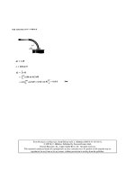
3.1.2 Power to weight ratio
When choosing the lowest and highest gearbox
gear ratios, the most important factor to consider
is not just the available engine power but also the
weight of the vehicle and any load it is expected to
propel. Consequently, the power developed per
unit weight of laden vehicle has to be known. This
is usually expressed as the power to weight ratio.
i.e.
Power to weight
ratio
Brake power developed
Laden weight of vehicle
There is a vast difference between the power to
weight ratio for cars and commercial vehicles
which is shown in the following examples.
Determine the power to weight ratio for the
following modes of transport:
a) A car fully laden with passengers and luggage
weighs 1.2 tonne and the maximum power pro-
duced by the engine amounts to 120 kW.
b) A fully laden articulated truck weighs 38 tonne
and a 290 kW engine is used to propel this load.
a) Power to weight ratio
120
1:2
100 kW/tonne
b) Power to weight ratio
290
38
7:6 kW/tonne.
3.1.3 Ratio span
Another major consideration when selecting gear
ratios is deciding upon the steepest gradient the
vehicle is expected to climb (this may normally be
taken as 20%, that is 1 in 5) and the maximum level
road speed the vehicle is expected to reach in top
gear with a small surplus of about 0.2% grade-
ability.
The two extreme operating conditions just
described set the highest and lowest gear ratios.
To fix these conditions, the ratio of road speed in
highest gear to road speed in lowest gear at a given
engine speed should be known. This quantity is
referred to as the ratio span.
i.e. Ratio span
Road speed in highest gear
Road speed in lowest gear
(both road speeds being achieved at similar engine
speed).
Car and light van gearboxes have ratio spans of
about 3.5:1 if top gear is direct, but with overdrive
this may be increased to about 4.5:1. Large com-
mercial vehicles which have a low power to weight
ratio, and therefore have very little surplus power
when fully laden, require ratio spans of between 7.5
and 10:1, or even larger for special applications.
An example of the significance of ratio span is
shown as follows:
Calculate the ratio span for both a car and heavy
commercial vehicle from the data provided.
Type of vehicle Gear Ratio km/h/1000
rev/min
Car Top 0.7 39
First 2.9 9.75
Commercial Top 1.0 48
vehicle (CV) First 6.35 6
Car ratio span
39
9:75
4:0X1
Commercial vehicle ratio span
48
6
8:0X1
3.1.4 Engine torque rise and speed operating
range (Fig. 3.2)
Commercial vehicle engines used to pull large loads
are normally designed to have a positive torque
rise curve, that is from maximum speed to peak
torque with reducing engine speed the available
torque increases (Fig. 3.2). The amount of engine
torque rise is normally expressed as a percentage of
the peak torque from maximum speed (rated
power) back to peak torque.
% torque rise
Maximum speed torque
Peak torque
 100
61
The torque rise can be shaped depending upon
engine design and taking into account such features
as naturally aspirated, resonant induction tuned,
turbocharged, turbocharged with intercooling and
so forth. Torque rises can vary from as little as 5 to
as high as 50%, but the most common values for
torque rise range from 15 to 30%.
A large torque rise characteristic raises the
engine's operating ability to overcome increased
loads if the engine's speed is pulled down caused
by changes in the road conditions, such as climbing
steeper gradients, and so tends to restore the ori-
ginal running conditions. If the torque rise is small
it cannot help as a buffer to supplement the high
torque demands and the engine speed will rapidly
fade. Frequent gear changes therefore become
necessary compared to engines operating with
high torque rise characteristics. Once the engine
speed falls below peak torque, the torque rise
becomes negative and the pulling ability of the
engine drops off very quickly.
Vehicle driving technique should be such that
engines are continuously driven between the speed
range of peak torque and governed speed. The
driver can either choose to operate the engine's
speed in a range varying just below the maximum
rated power to achieve maximum performance and
journey speed or, to improve fuel economy, wear
and noise, within a speed range of between 200 to
400 rev/min on the positive torque rise side of the
engine torque curve that is in a narrow speed band
just beyond peak torque. Fig. 3.2 shows that the
economy speed range operates with the specific fuel
consumption at its minimum and that the engine
speed band is in the most effective pulling zone.
3.2 Five speed and reverse synchromesh gearboxes
With even wider engine speed ranges (1000 to 6000
rev/min) higher car speeds (160 km/h and more)
and high speed motorways, it has become desirable,
and in some cases essential, to increase the number
of traditional four speed ratios to five, where the
fifth gear, and sometimes also the fourth gear, is an
overdrive ratio. The advantages of increasing the
number of ratio steps are several; not only does
the extra gear provide better acceleration response,
but it enables the maximum engine rotational speed
to be reduced whilst in top gear cruising, fuel
Fig. 3.2 Engine performance and gear split chart for an eight speed gearbox
62
consumption is improved and engine noise and wear
are reduced. Typical gearratios for both four and five
speed gearboxes are as shown in Table 3.1.
The construction and operation of four speed
gearboxes was dealt with in Vehicle and Engine
Technology. The next section deals with five speed
synchromesh gearboxes utilized for longitudinal
and transverse mounted engines.
3.2.1 Five speed and reverse double stage
synchromesh gearbox (Fig. 3.3)
With this arrangement of a five speed double stage
gearbox, the power input to the first motion shaft
passes to the layshaft and gear cluster via the first
stage pair of meshing gears. Rotary motion is
therefore conveyed to all the second stage layshaft
and mainshaft gears (Fig. 3.3). Because each pair of
second stage gears has a different size combination,
a whole range of gear ratios are provided. Each
mainshaft gear (whilst in neutral) revolves on the
mainshaft but at some relative speed to it. There-
fore, to obtain output powerflow, the selected
mainshaft gear has to be locked to the mainshaft.
This then completes the flow path from the first
motion shaft, first stage gears, second stage gears
and finally to the mainshaft.
In this example the fifth gear is an overdrive gear
so that to speed up the mainshaft output relative to
the input to the first motion shaft, a large layshaft
fifth gear wheel is chosen to mesh with a much
smaller mainshaft gear.
For heavy duty operations, a forced feed lubrica-
tion system is provided by an internal gear crescent
type oil pump driven from the rear end of the
layshaft (Fig. 3.3). This pump draws oil from the
base of the gearbox casing, pressurizes it and then
forces it through a passage to the mainshaft. The
oil is then transferred to the axial hole along the
centre of the mainshaft by way of an annular
passage formed between two nylon oil seals.
Lubrication to the mainshaft gears is obtained by
radial branch holes which feed the rubbing surfaces
of both mainshaft and gears.
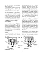
3.2.2 Five speed and reverse single stage
synchromesh gearbox (Fig. 3.4)
This two shaft gearbox has only one gear reduction
stage formed between pairs of different sized con-
stant mesh gear wheels to provide a range of gear
ratios. Since only one pair of gears mesh, compared
to the two pairs necessary for the double stage
gearbox, frictional losses are halved.
Power delivered to the input primary shaft can
follow five different flow paths to the secondary
shaft via first, second, third, fourth and fifth gear
wheel pairs, but only one pair is permitted to trans-
fer the drive from one shaft to another at any one
time (Fig. 3.4).
The conventional double stage gearbox is
designed with an input and output drive at either
end of the box but a more convenient and compact
arrangement with transaxle units where the final
drive is integral to the gearbox is to have the input
and output power flow provided at one end only of
the gearbox.
In the neutral position, first and second output
gear wheels will be driven by the corresponding
gear wheels attached to the input primary shaft,
but they will only be able to revolve about their
own axis relative to the output secondary shaft.
Third, fourth and fifth gear wheel pairs are driven
by the output second shaft and are free to revolve
only relative to the input primary shaft because
they are not attached to this shaft but use it only
as a supporting axis.
When selecting individual gear ratios, the appro-
priate synchronizing sliding sleeve is pushed
towards and over the dog teeth forming part of
the particular gear wheel required. Thus with first
and second gear ratios, the power flow passes from
the input primary shaft and constant mesh pairs of
gears to the output secondary shaft via the first and
second drive hub attached to this shaft. Gear
engagement is completed by the synchronizing
sleeve locking the selected output gear wheel to
the output secondary shaft. Third, fourth and
fifth gear ratios are selected when the third and
fourth or fifth gear drive hub, fixed to the input
primary shaft, is locked to the respective gear wheel
dog clutch by sliding the synchronizing sleeve in to
mesh with it. The power flow path is now trans-
ferred from the input primary shaft drive hub and
selected pair of constant mesh gears to the output
secondary shaft.
Table 3.1 Typical four and five speed gearbox gear
ratios
Five speed box Four speed box
Gear Ratio Gear Ratio
top 0.8 top 1.0
4 1.0 3 1.3
3 1.4 2 2.1
2 2.0 1 3.4
1 3.5 R 3.5
R 3.5
63
Transference of power from the gearbox output
secondary shaft to the differential left and right
hand drive shafts is achieved via the final drive
pinion and gear wheel which also provide a per-
manent gear reduction (Fig. 3.4). Power then flows
from the differential cage which supports the final
drive gear wheel to the cross-pin and planet gears
where it then divides between the two side sun gears
and accordingly power passes to both stub drive
shafts.
3.3 Gear synchronization and engagement
The gearbox basically consists of an input shaft
driven by the engine crankshaft by way of the
clutch and an output shaft coupled indirectly either
Fig. 3.3 Five speed and reverse double stage synchromesh gearbox
64
through the propellor shaft or intermediate gears to
the final drive. Between these two shafts are pairs of
gear wheels of different size meshed together.
If the gearbox is in neutral, only one of these
pairs of gears is actually attached rigidly to one of
these shafts while the other is free to revolve on the
second shaft at some speed determined by the exist-
ing speeds of the input and output drive shafts.
To engage any gear ratio the input shaft has to
be disengaged from the engine crankshaft via the
Fig. 3.4 Five speed and reverse single stage synchromesh gearbox with integral final drive (transaxle unit)
65
clutch to release the input shaft drive. It is then only
the angular momentum of the input shaft, clutch
drive plate and gear wheels which keeps them revol-
ving. The technique of good gear changing is to be
able to judge the speeds at which the dog teeth of
both the gear wheel selected and output shaft are
rotating at a uniform speed, at which point in time
the dog clutch sleeve is pushed over so that both sets
of teeth engage and mesh gently without grating.
Because it is difficult to know exactly when to
make the gear change a device known as the syn-
chromesh is utilized. Its function is to apply a fric-
tion clutch braking action between the engaging
gear and drive hub of the output shaft so that
their speeds will be unified before permitting the
dog teeth of both members to contact.
Synchromesh devices use a multiplate clutch or a
conical clutch to equalise the input and output
rotating members of the gearbox when the process
of gear changing is taking place. Except for special
applications, such as in some splitter and range
change auxiliary gearboxes, the conical clutch
method of synchronization is generally employed.
With the conical clutch method of producing silent
gear change, the male and female cone members
are brought together to produce a synchronizing
frictional torque of sufficient magnitude so that one
or both of the input and output members' rotational
speed or speeds adjust automatically until they
revolve as one. Once this speed uniformity has been
achieved, the end thrust applied to the dog clutch
sleeve is permitted to nudge the chamfered dog teeth
of both members into alignment, thereby enablingthe
two sets of teeth to slide quietly into engagement.
3.3.1 Non-positive constant load synchromesh
unit (Fig. 3.5(a, b and c))
When the gear stick is in the neutral position the
spring loaded balls trapped between the inner and
outer hub are seated in the circumferential groove
formed across the middle of the internal dog teeth
(Fig. 3.5(a)). As the driver begins to shift the gear
stick into say top gear (towards the left), the outer
and inner synchromesh hubs move as one due to the
radial spring loading of the balls along the splines
formed on themain shaft until thefemale cone of the
outer hub contacts the male cone of the first motion
gear (Fig. 3.5(b)). When the pair of conical faces
contact, frictional torque will be generated due to
the combination of the axial thrust and the differ-
ence in relative speed of both input and output shaft
members. If sufficient axial thrust is applied to the
outer hub, the balls will be depressed inwards
against the radial loading of the springs. Immedi-
ately the balls are pushed out of their groove, the
chamfered edges of the outer hub's internal teeth will
then be able to align with the corresponding teeth
spacing on the first motion gear. Both sets of teeth
will now be able to mesh so that the outer hub can be
moved into the fully engaged position (Fig. 3.5(c)).
Note the bronze female cone insert frictional face
is not smooth, but consists of a series of tramline
grooves which assist in cutting away the oil film so
that a much larger synchronizing torque will be
generated to speed up the process.
3.3.2 Positive baulk ring synchromesh unit
(Fig. 3.6(a, b and c))
The gearbox mainshaft rotates at propellor shaft
speed and, with the clutch disengaged, the first
motion shaft gear, layshaft cluster gears, and
mainshaft gears rotate freely.
Drive torque will be transmitted when a gear
wheel is positively locked to the mainshaft. This is
achieved by means of the outer synchromesh hub
internal teeth which slide over the inner synchro-
mesh hub splines (Fig. 3.6(a)) until they engage
with dog teeth formed on the constant mesh gear
wheel being selected.
When selecting and engaging a particular gear
ratio, the gear stick slides the synchromesh outer
hub in the direction of the chosen gear (towards
the left). Because the shift plate is held radially
outwards by the two energizing ring type springs
and the raised middle hump of the plate rests in the
groove formed on the inside of the hub, the end of
the shift plate contacts the baulking ring and pushes
it towards and over the conical surface, forming
part of the constant mesh gear wheel (Fig. 3.6(b)).
The frictional grip between the male and female
conical members of the gear wheel and baulking
ring and the difference in speed will cause the baulk-
ing ring to be dragged around relative to the inner
hub and shift plate within the limits of the clearance
between the shift plate width and that of the
recessed slot in the baulking ring. Owing to the
designed width of the shift plate slot in the baulking
ring, the teeth on the baulking ring are now out of
alignment with those on the outer hub by approxi-
mately half a tooth width, so that the chamfered
faces of the teeth of the baulking ring and outer hub
bear upon each other.
As the baulking ring is in contact with the gear
cone and the outer hub, the force exerted by the
driver on the gear stick presses the baulking ring
female cone hard against the male cone of the gear.
Frictional torque between the two surfaces will
eventually cause these two members to equalize
66
Fig. 3.5 Non-positive constant load synchromesh unit
67
Fig. 3.6 (a±c) Positive baulk ring synchromesh unit
68
their speeds. Until this takes place, full engagement
of the gear and outer hub dog teeth is prevented by
the out of alignment position of the baulking ring
teeth. When the gear wheel and main shaft have
unified their speeds, the synchronizing torque will
have fallen to zero so that the baulking ring is no
longer dragged out of alignment. Therefore the
outer hub can now overcome the baulk and follow
through to make a positive engagement between
hub and gear (Fig. 3.6(c)). It should be understood
that the function of the shift plate and springs is to
transmit just sufficient axial load to ensure a rapid
bringing together of the mating cones so that the
baulking ring dog teeth immediately misalign with
their corresponding outer hub teeth. Once the cone
faces contact, they generate their own friction
torque which is sufficient to flick the baulking
ring over, relative to the outer hub. Thus the cham-
fers of both sets of teeth contact and oppose further
outer hub axial movement towards the gear dog
teeth.
3.3.3 Positive baulk pin synchromesh unit
(Fig. 3.7(a, b, c and d))
Movement of the selector fork synchronizing sleeve
to the left (Fig. 3.7(a and b)) forces the female
(internal) cone to move into contact with the male
(external) cone on the drive gear. Frictional torque
will then synchronize (unify) the input and output
speeds. Until speed equalization is achieved, the col-
lars on the three thrust pins (only one shown) will be
pressed hard into the enlarged position of the slots
(Fig. 3.5(c)) in the synchronizing sleeve owing to the
frictional drag when the speeds are dissimilar. Under
these conditions, unless extreme pressure is exerted,
the dog teeth cannot be crushed by forcing the collars
into the narrow portion of the slots. However, when
the speeds of the synchromesh hub and drive gear are
equal (synchronized) the collars tend to `float' in
the enlarged portion of the slots, there is only the
pressure of the spring loaded balls to be overcome.
The collars will then slide easily into the narrow
portion of the slots (Fig. 3.5(d)) allowing the syn-
chronizer hub dog teeth to shift in to mesh with the
dog teeth on the driving gear.
3.3.4 Split baulk pin synchromesh unit
(Fig. 3.8(a, b, c and d))
The synchronizing assembly is composed of two
thick bronze synchronizing rings with tapered
female conical bores, and situated between them
is a hardened steel drive hub internally splined with
external dog teeth at each end (Fig. 3.8(a)). Three
shouldered pins, each with a groove around its
centre, hold the bronze synchronizing cone rings
apart. Alternating with the shouldered pins on the
same pitch circle are diametrically split pins, the
ends of which fit into blind bores machined in
the synchronizing cone rings. The pin halves are
sprung apart, so that a chamfered groove around the
middle of each half pin registers with a chamfered
hole in the drive hub.
If the gearbox is in the neutral position, both sets
of shouldered and split pins are situated with their
grooves aligned with the central drive hub (Fig.
3.8(a and b)).
When an axial load is applied to the drive hub by
the gear stick, it moves over (in this case to the left)
until the synchronizing ring is forced against the
adjacent first motion gear cone. The friction (syn-
chronizing) torque generated between the rubbing
tapered surfaces drags the bronze synchronizing
ring relative to the mainshaft and drive hub until
thegroovesintheshoulderedpinsarewedgedagainst
the chamfered edges of the drive hub (Fig. 3.8(c)) so
that further axial movement is baulked.
Immediately the input and output shaft speeds
are similar, that is, synchronization has been
achieved, the springs in the split pins are able to
expand and centralize the shouldered pins relative
to the chamfered holes in the drive hub. The drive
hub can now ride out of the grooves formed around
the split pins, thus permitting the drive hub to shift
further over until the internal and external dog
teeth of both gear wheel hub mesh and fully engage
(Fig. 3.8(d)).
3.3.5 Split ring synchromesh unit
(Fig. 3.9(a, b, c and d))
In the neutral position the sliding sleeve sits cen-
trally over the drive hub (Fig. 3.9(a)). This permits
the synchronizing ring expander band and thrust
block to float within the constraints of the recess
machine in the side of the gear facing the drive hub
(Fig. 3.9(b)).
For gear engagement to take place, the sliding
sleeve is moved towards the gear wheel selected (to
the left) until the inside chamfer of the sliding sleeve
contacts the bevelled portion of the synchronizing
ring. As a result, the synchronizing ring will be
slightly compressed and the friction generated
between the two members then drags the synchron-
izing ring round in the direction of whichever
member is rotating fastest, be it the gear or driven
hub. At the same time, the thrust block is pulled
round so that it applies a load to one end of the
expander band, whilst the other end is restrained
from moving by the anchor block (Fig. 3.9(c)).
69
Whilst this is happening the expander is also
pushed radially outwards. Consequently, there
will be a tendency to expand the synchronizing
slit ring, but this will be opposed by the chamfered
mouth of the sliding sleeve. This energizing action
attempting to expand the synchronizing ring pre-
vents the sliding sleeve from completely moving
over and engaging the dog teeth of the selected
Fig. 3.7 (a±d) Positive baulk pin synchromesh unit
70
gear wheel until both the drive hub and constant
mesh gear wheel are revolving at the same speed.
When both input and output members are uni-
fied, that is, rotating as one, there cannot be any
more friction torque because there is no relative
speed to create the frictional drag. Therefore
the expander band immediately stops exerting
radial force on the inside of the synchronizing ring.
Fig. 3.8 (a±c) Split baulk pin synchromesh unit
71