Advanced Vehicle Technology Episode 1 Part 2 doc
Bạn đang xem bản rút gọn của tài liệu. Xem và tải ngay bản đầy đủ của tài liệu tại đây (336.95 KB, 20 trang )
floor, a rule or tape is used to measure the distances
between centres both transversely and diagonally.
These values are then chalked along their respective
lines. Misalignment or error is observed when a
pair of transverse or diagonal dimensions differ
and further investigation will thus be necessary.
Note that transverse and longitudinal dimen-
sions are normally available from the manufac-
turer's manual and differences between paired
diagonals indicates lozenging of the framework
due to some form of abnormal impact which has
previously occurred.
1.2 Engine, transmission and body structure
mountings
1.2.1 Inherent engine vibrations
The vibrations originating within the engine are
caused by both the cyclic acceleration of the reci-
procating components and the rapidly changing
cylinder gas pressure which occurs throughout
each cycle of operation.
Both the variations of inertia and gas pressure
forces generate three kinds of vibrations which are
transferred to the cylinder block:
1 Vertical and/or horizontal shake and rock
2 Fluctuating torque reaction
3 Torsional oscillation of the crankshaft
1.2.2 Reasons for flexible mountings
It is the objective of flexible mounting design to
cope with the many requirements, some having
conflicting constraints on each other. A list of the
duties of these mounts is as follows:
1 To prevent the fatigue failure of the engine and
gearbox support points which would occur if
they were rigidly attached to the chassis or
body structure.
2 To reduce the amplitude of any engine vibration
which is being transmitted to the body structure.
3 To reduce noise amplification which would occur
if engine vibration were allowed to be transferred
directly to the body structure.
Fig. 1.9 Body underframe alignment checks
12
4 To reduce human discomfort and fatigue by
partially isolating the engine vibrations from
the body by means of an elastic media.
5 To accommodate engine block misalignment
and to reduce residual stresses imposed on the
engine block and mounting brackets due to
chassis or body frame distortion.
6 To prevent road wheel shocks when driving
over rough ground imparting excessive rebound
movement to the engine.
7 To prevent large engine to body relative move-
ment due to torque reaction forces, particularly
in low gear, which would cause excessive mis-
alignment and strain on such components as
the exhaust pipe and silencer system.
8 To restrict engine movement in the fore and aft
direction of the vehicle due to the inertia of the
engine acting in opposition to the accelerating
and braking forces.
1.2.3 Rubber flexible mountings (Figs 1.10, 1.11
and 1.12)
A rectangular block bonded between two metal
plates may be loaded in compression by squeezing
the plates together or by applying parallel but
opposing forces to each metal plate. On compres-
sion, the rubber tends to bulge out centrally from
the sides and in shear to form a parallelogram
(Fig. 1.10(a)).
To increase the compressive stiffness of the
rubber without greatly altering the shear stiffness,
an interleaf spacer plate may be bonded in between
the top and bottom plate (Fig. 1.10(b)). This inter-
leaf plate prevents the internal outward collapse of
the rubber, shown by the large bulge around the
sides of the block, when no support is provided,
whereas with the interleaf a pair of much smaller
bulges are observed.
When two rubber blocks are inclined to each other
to form a `V' mounting, see Fig. 1.11, the rubber will
be loaded in both compression and shear shown by
the triangle of forces. The magnitude of compressive
force will be given by W
c
and the much smaller shear
force by W
S
. This produces a resultant reaction force
W
R
. The larger the wedge angle  , the greater the
proportion of compressive load relative to the shear
load the rubber block absorbs.
The distorted rubber provides support under
light vertical static loads approximately equal in
both compression and shear modes, but with
heavier loads the proportion of compressive stiffness
Fig. 1.10 (a and b) Modes of loading rubber blocks
Fig. 1.11 `V' rubber block mounting
13
to that of shear stiffness increases at a much faster
rate (Fig. 1.12). It should also be observed that the
combined compressive and shear loading of the
rubber increases in direct proportion to the static
deflection and hence produces a straight line graph.
1.2.4 Axis of oscillation (Fig. 1.13)
The engine and gearbox must be suspended so that
it permits the greatest degree of freedom when
oscillating around an imaginary centre of rotation
known as the principal axis. This principal axis
produces the least resistance to engine and gearbox
sway due to their masses being uniformly distrib-
uted about this axis. The engine can be considered
to oscillate around an axis which passes through
the centre of gravity of both the engine and gearbox
(Figs 1.13(a, b and c)). This normally produces an
axis of oscillation inclined at about 10±20
to the
crankshaft axis. To obtain the greatest degree of
freedom, the mounts must be arranged so that they
offer the least resistance to shear within the rubber
mounting.
1.2.5 Six modes of freedom of a suspended body
(Fig. 1.14)
If the movement of a flexible mounted engine is
completely unrestricted it may have six modes of
vibration. Any motion may be resolved into three
linear movements parallel to the axes which pass
through the centre of gravity of the engine but at
right angles to each other and three rotations about
these axes (Fig. 1.14).
These modes of movement may be summarized
as follows:
Linear motions Rotational motions
1 Horizontal 4 Roll
longitudinal 5 Pitch
2 Horizontal lateral 6 Yaw
3 Vertical
1.2.6 Positioning of engine and gearbox
mountings (Fig. 1.15)
If the mountings are placed underneath the com-
bined engine and gearbox unit, the centre of gravity
is well above the supports so that a lateral (side)
force acting through its centre of gravity, such as
experienced when driving round a corner, will cause
the mass to roll (Fig. 1.15(a)). This condition is
undesirable and can be avoided by placing the
mounts on brackets so that they are in the
same plane as the centre of gravity (Fig. 1.15(b)).
Thus the mounts provide flexible opposition to
any side force which might exist without creating a
roll couple. This is known as a decoupled condition.
An alternative method of making the natural
modes of oscillation independent or uncoupled is
achieved by arranging the supports in an inclined
`V' position (Fig. 1.15(c)). Ideally the aim is to
make the compressive axes of the mountings meet
at the centre of gravity, but due to the weight of the
power unit distorting the rubber springing the
inter-section lines would meet slightly below this
point. Therefore, the mountings are tilted so that
the compressive axes converge at some focal point
above the centre of gravity so that the actual lines
of action of the mountings, that is, the direction
of the resultant forces they exert, converge on the
centre of gravity (Fig. 1.15(d)).
The compressive stiffness of the inclined mounts
can be increased by inserting interleafs between
the rubber blocks and, as can be seen in
Fig. 1.15(e), the line of action of the mounts con-
verges at a lower point than mounts which do not
have interleaf support.
Engine and gearbox mounting supports are
normally of the three or four point configuration.
Petrol engines generally adopt the three point
support layout which has two forward mounts
(Fig. 1.13(a and c)), one inclined on either side of
the engine so that their line of action converges on
the principal axis, while the rear mount is supported
centrally at the rear of the gearbox in approximately
the same plane as the principal axis. Large diesel
engines tend to prefer the four point support
Fig. 1.12 Load±deflection curves for rubber block
14
arrangement where there are two mounts either side
of the engine (Fig. 1.13(b)). The two front mounts
are inclined so that their lines of action pass through
the principal axis, but the rear mounts which are
located either side of the clutch bell housing are not
inclined since they are already at principal axis level.
1.2.7 Engine and transmission vibrations
Natural frequency of vibration (Fig. 1.16) Asprung
body when deflected and released will bounce up and
down at a uniform rate. The amplitude of this cyclic
movement will progressively decrease and the num-
ber of oscillations per minute of the rubber mounting
is known as its natural frequency of vibration.
There is a relationship between the static deflec-
tion imposed on the rubber mount springing by the
suspended mass and the rubber's natural frequency
of vibration, which may be given by
n
0
30
p
x
Fig. 1.13 Axis of oscillation and the positioning of the power unit flexible mounts
15
where n
0 =
natural frequency of vibration
(vib/min)
x = static deflection of the rubber (m)
This relationship between static deflection and
natural frequency may be seen in Fig. 1.16.
Resonance Resonance is the unwanted synchron-
ization of the disturbing force frequency imposed by
the engine out of balance forces and the fluctuating
cylinder gas pressure and the natural frequency of
oscillation of the elastic rubber support mounting,
i.e. resonance occurs when
n
n
0
1
where n = disturbing frequency
n
0
= natural frequency
Transmissibility (Fig. 1.17) When the designer
selects the type of flexible mounting the Theory of
Transmissibility can be used to estimate critical
resonance conditions so that they can be either
prevented or at least avoided.
Transmissibility (T) may be defined as the ratio
of the transmitted force or amplitude which passes
through the rubber mount to the chassis to that of
the externally imposed force or amplitude generated
by the engine:
T
F
t
F
d
1
1 À
n
n
0
2
where F
t
transmitted force or amplitude
F
d
imposed disturbing force or
amplitude
This relationship between transmissibility and
the ratio of disturbing frequency and natural
frequency may be seen in Fig. 1.17.
Fig. 1.14 Six modes of freedom for a suspended block
Fig. 1.16 Relationship of static deflection and natural
frequency
16
Fig. 1.15 (a±e) Coupled and uncoupled mounting points
17
The transmissibility to frequency ratio graph
(Fig. 1.17) can be considered in three parts as follows:
Range(I) Thisistheresonancerangeand shouldbe
avoided. It occurs when the disturbing frequency
is very near to the natural frequency. If steel mounts
are used, a critical vibration at resonance would go
to infinity, but natural rubber limits the trans-
missibility to around 10. If Butyl synthetic rubber is
adopted, its damping properties reduce the peak
transmissibility to about 2
1
¤
2
. Unfortunately, high
damping rubber compounds such as Butyl rubber
are temperature sensitive to both damping and
dynamic stiffness so that during cold weather a
noticeably harsher suspension of the engine results.
Damping of the engine suspension mounting is
necessary to reduce the excessive movement of a
flexible mounting when passing through resonance,
but at speeds above resonance more vibration is
transmitted to the chassis or body structure than
would occur if no damping was provided.
Range (II) This is the recommended working
range where the ratio of the disturbing frequency
to that of the natural frequency of vibration of the
rubber mountings is greater than 1
1
¤
2
and the trans-
missibility is less than one. Under these conditions
off-peak partial resonance vibrations passing to the
body structure will be minimized.
Range (III) This is known as the shock reduction
range and only occurs when the disturbing
frequency is lower than the natural frequency.
Generally it is only experienced with very soft
rubber mounts and when the engine is initially
cranked for starting purposes and so quickly passes
through this frequency ratio region.
Example An engine oscillates vertically on its
flexible rubber mountings with a frequency of 800
vibrations per minute (vpm). With the information
provided answer the following questions:
a) From the static deflection±frequency graph,
Fig. 1.16, or by formula, determine the natural fre-
quency of vibration when the static deflection of
the engine is 2 mm and then find the disturbing to
natural frequency ratio. Comment on theseresults.
b) If the disturbing to natural frequency ratio is
increased to 2.5 determine the natural frequency
Fig. 1.17 Relationship of transmissibility and
the ratio of disturbing and natural frequencies
for natural rubber, Butyl rubber and steel
18
of vibration and the new static deflection of the
engine. Comment of these conditions.
a) n
0
30
p
x
30
p
0:002
30
0:04472
670:84 vib/min
;
n
n
0
800
670:84
1:193
The ratio 1.193 is very near to the resonance
condition and should be avoided by using softer
mounts.
b)
n
n
0
800
n
0
2:5
; n
0
800
2:5
320 vib/min
Now n
0
30
p
x
thus
p
x
30
n
0
; x
30
n
0
2
30
320
2
0:008789 m or 8:789 mm
A low natural frequency of 320 vib/min is well
within the insulation range, therefore from either
the deflection±frequency graph or by formula
the corresponding rubber deflection necessary is
8.789 mm when the engine's static weight bears
down on the mounts.
1.2.8 Engine to body/chassis mountings
Engine mountings are normally arranged to
provide a degree of flexibility in the horizontal
longitudinal, horizontal lateral and vertical axis of
rotation. At the same time they must have suffi-
cient stiffness to provide stability under shock
loads which may come from the vehicle travelling
over rough roads. Rubber sprung mountings
suitably positioned fulfil the following functions:
1 Rotational flexibility around the horizontal
longitudinal axis which is necessary to allow the
impulsive inertia and gas pressure components
of the engine torque to be absorbed by rolling of
the engine about the centre of gravity.
2 Rotational flexibility around both the horizontal
lateral and the vertical axis to accommodate any
horizontal and vertical shake and rock caused by
unbalanced reciprocating forces and couples.
1.2.9 Subframe to body mountings
(Figs 1.6 and 1.19)
One of many problems with integral body design is
the prevention of vibrations induced by the engine,
transmissionand road wheelsfrombeing transmitted
through the structure. Some manufacturers adopt a
subframe (Fig. 1.6(a, b and c)) attached by resilient
mountings (Fig. 1.19(a and b)) to the body to which
the suspension assemblies, and in some instances the
engine and transmission, are attached. The mass
of the subframes alone helps to damp vibrations.
It also simplifies production on the assembly line,
and facilitates subsequent overhaul or repairs.
In general, the mountings are positioned so that
they allow strictly limited movement of the
subframe in some directions but provide greater
freedom in others. For instance, too much lateral
freedom of a subframe for a front suspension
assembly would introduce a degree of instability
into the steering, whereas some freedom in vertical
and longitudinal directions would improve the
quality of a ride.
1.2.10 Types of rubber flexible mountings
A survey of typical rubber mountings used for
power units, transmissions, cabs and subframes
are described and illustrated as follows:
Double shear paired sandwich mounting (Fig.
1.18(a)) Rubber blocks are bonded between the
jaws of a `U' shaped steel plate and a flat interleaf
plate so that a double shear elastic reaction takes
place when the mount is subjected to vertical load-
ing. This type of shear mounting provides a large
degree of flexibility in the upright direction and
thus rotational freedom for the engine unit about
its principal axis. It has been adopted for both
engine and transmission suspension mounting
points for medium-sized diesel engines.
Double inclined wedge mounting (Fig. 1.18(b)) The
inclined wedge angle pushes the bonded rubber
blocks downwards and outwards against the
bent-up sides of the lower steel plate when loaded
in the vertical plane. The rubber blocks are subjected
to both shear and compressive loads and the propor-
tion of compressive to shear load becomes greater
with vertical deflection. This form of mounting is
suitable for single point gearbox supports.
Inclined interleaf rectangular sandwich mounting
(Fig. 1.18(c)) These rectangular blocks are
19
Fig. 1.18 (a±h) Types of rubber flexible mountings
20
Fig. 1.18 contd
21
designed to be used with convergent `V' formation
engine suspension system where the blocks are
inclined on either side of the engine. This configura-
tion enables the rubber to be loaded in both shear
and compression with the majority of engine rota-
tional flexibility being carried out in shear. Vertical
deflection due to body pitch when accelerating or
braking is absorbed mostly in compression. Vertical
elastic stiffness may be increased without greatly
effecting engine roll flexibility by having metal
spacer interleafs bonded into the rubber.
Double inclined wedge with longitudinal control
mounting (Fig. 1.18(d)) Where heavy vertical
loads and large rotational reactions are to be
absorbed, double inclined wedge mounts positioned
on either side of the power unit's bell housing
at principal axis level may be used. Longitudinal
movement is restricted by the double `V' formed
between the inner and two outer members seen in
a plan view. This `V' and wedge configuration pro-
vides a combined shear and compressive strain to
the rubber when there is a relative fore and aft move-
ment between the engine and chassis, in addition to
that created by the vertical loading of the mount.
This mounting's major application is for the rear
mountings forming part of a four point suspension
for heavy diesel engines.
Metaxentric bush mounting (Fig. 1.18(e)) When
the bush is in the unloaded state, the steel inner
sleeve is eccentric relative to the outer one so that
Fig. 1.18 contd
22
there is more rubber on one side of it than on the
other. Precompression is applied to the rubber
expanding the inner sleeve. The bush is set so that
the greatest thickness of rubber is in compression
in the laden condition. A slot is incorporated in
the rubber on either side where the rubber is at its
minimum in such a position as to avoid stressing
any part of it in tension.
When installed, its stiffness in the fore and aft
direction is greater than in the vertical direction, the
ratio being about 2.5 : 1. This type of bush provides
a large amount of vertical deflection with very little
fore and aft movement which makes it suitable for
rear gearbox mounts using three point power unit
suspension and leaf spring eye shackle pin bushes.
Metacone sleeve mountings (Fig. 1.18(f and g))
These mounts are formed from male and female
conical sleeves, the inner male member being
centrally positioned by rubber occupying the
space between both surfaces (Fig. 1.18(f)). During
vertical vibrational deflection, the rubber between
the sleeves is subjected to a combined shear and
compression which progressively increases the stiff-
ness of the rubber as it moves towards full distor-
tion. The exposed rubber at either end overlaps the
flanged outer sleeve and there is an upper and
lower plate bolted rigidly to the ends of the inner
sleeve. These plates act as both overload (bump)
and rebound stops, so that when the inner member
deflects up or down towards the end of its move-
ment it rapidly stiffens due to the surplus rubber
being squeezed in between. Mounts of this kind are
used where stiffness is needed in the horizontal
direction with comparative freedom of movement
for vertical deflection.
An alternative version of the Metacone mount
uses a solid aluminium central cone with a flanged
pedestal conical outer steel sleeve which can be
bolted directly onto the chassis side member, see
Fig. 1.18(g). An overload plate is clamped between
the inner cone and mount support arm, but no
rebound plate is considered necessary.
These mountings are used for suspension appli-
cations such as engine to chassis, cab to chassis,
bus body and tanker tanks to chassis.
Double inclined rectangular sandwich mounting
(Fig. 1.18(h)) A pair of rectangular sandwich
rubber blocks are supported on the slopes of a
triangular pedestal. A bridging plate merges the
resilience of the inclined rubber blocks so that
they provide a combined shear and compressive
distortion within the rubber. Under small deflec-
tion conditions the shear and compression is
almost equal, but as the load and thus deflection
increases, the proportion of compression over the
shear loading predominates.
These mounts provide very good lateral stability
without impairing vertical deflection flexibility and
progressive stiffness control. When used for road
wheel axle suspension mountings, they offer good
insulation against road and other noises.
Flanged sleeve bobbin mounting with rebound
control (Fig. 1.19(a and b)) These mountings
have the rubber moulded partially around the outer
flange sleeve and in between this sleeve and an inner
tube. A central bolt attaches the inner tube to the
body structure while the outer member is bolted on
two sides to the subframe.
When loaded in the vertical downward direction,
the rubber between the sleeve and tube walls will be
in shear and the rubber on the outside of the
flanged sleeve will be in compression.
There is very little relative sideway movement
between the flanged sleeve and inner tube due to
rubber distortion. An overload plate limits the down-
ward deflection and rebound is controlled by the
lower plate and the amount and shape of rubber
trapped between it and the underside of the flanged
sleeve. A reduction of rubber between the flanged
sleeve and lower plate (Fig. 1.19(a)) reduces the
rebound, but an increase in depth of rubber increases
rebound (Fig. 1.19(b)). The load deflection charac-
teristics are given for both mounts in Fig. 1.19c.
These mountings are used extensively for body to
subframe and cab to chassis mounting points.
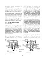
Hydroelastic engine mountings (Figs 1.20(a±c) and
1.21) A flanged steel pressing houses and sup-
ports an upper and lower rubber spring diaphragm.
The space between both diaphragms is filled and
sealed with fluid and is divided in two by a separator
plate and small transfer holes interlink the fluid
occupying these chambers (Fig. 1.20(a and b)).
Under vertical vibratory conditions the fluid will
be displaced from one chamber to the other
through transfer holes. During downward deflec-
tion (Fig. 1.20(b)), both rubber diaphragms are
subjected to a combined shear and compressive
action and some of the fluid in the upper chamber
will be pushed into the lower and back again by
way of the transfer holes when the rubber rebounds
(Fig. 1.20(a)). For low vertical vibratory frequencies,
23
the movement of fluid between the chambers is
unrestricted, but as the vibratory frequencies
increase, the transfer holes offer increasing resist-
ance to the flow of fluid and so slow down the up
and down motion of the engine support arm. This
damps and reduces the amplitude of mountings
vertical vibratory movement over a number of
cycles. A comparison of conventional rubber and
hydroelastic damping resistance over the normal
operating frequency range for engine mountings is
shown in Fig. 1.20(c).
Instead of adopting a combined rubber mount
with integral hydraulic damping, separate diagon-
ally mounted telescopic dampers may be used in
conjunction with inclined rubber mounts to reduce
both vertical and horizontal vibration (Fig. 1.21).
1.3 Fifth wheel coupling assembly
(Fig. 1.22(a and b))
The fifth wheel coupling attaches the semi-trailer to
the tractor unit. This coupling consists of a semi-
circular table plate with a central hole and a vee
section cut-out towards the rear (Fig. 1.22(b)).
Attached underneath this plate are a pair of pivot-
ing coupling jaws (Fig. 1.22(a)). The semi-trailer
has an upper fifth wheel plate welded or bolted to
the underside of its chassis at the front and in the
centre of this plate is bolted a kingpin which faces
downwards (Fig. 1.22(a)).
When the trailer is coupled to the tractor unit,
this upper plate rests and is supported on top of the
tractor fifth wheel table plate with the two halves of
the coupling jaws engaging the kingpin. To permit
Fig. 1.19 (a±c) Flanged sleeve bobbin mounting with
rebound control
24
relative swivelling between the kingpin and jaws,
the two interfaces of the tractor fifth wheel
tables and trailer upper plate should be heavily
greased. Thus, although the trailer articulates
about the kingpin, its load is carried by the tractor
table.
Flexible articulation between the tractor and
semi-trailer in the horizontal plane is achieved by
permitting the fifth wheel table to pivot on hori-
zontal trunnion bearings that lie in the same vertical
plane as the kingpin, but with their axes at right
angles to that of the tractor's wheel base (Fig.
1.22(b)). Rubber trunnion rubber bushes normally
provide longitudinal oscillations of about Æ10
.
The fifth wheel table assembly is made from
either a machined cast or forged steel sections, or
from heavy section rolled steel fabrications, and the
upper fifth wheel plate is generally hot rolled steel
welded to the trailer chassis. The coupling locking
system consisting of the jaws, pawl, pivot pins and
kingpin is produced from forged high carbon man-
ganese steels and the pressure areas of these com-
ponents are induction hardened to withstand shock
loading and wear.
1.3.1 Operation of twin jaw coupling
(Fig. 1.23(a±d))
With the trailer kingpin uncoupled, the jaws will be
in their closed position with the plunger withdrawn
from the lock gap between the rear of the jaws,
which are maintained in this position by the pawl
contacting the hold-off stop (Fig. 1.23(a)). When
coupling the tractor to the trailer, the jaws of the
Fig. 1.20 (a±c) Hydroelastic engine mount
25
fifth wheel strike the kingpin of the trailer. The
jaws are then forced open and the kingpin enters
the space between the jaws (Fig. 1.23(b)). The king-
pin contacts the rear of the jaws which then
automatically pushes them together. At the same
time, one of the coupler jaws causes the trip pin to
strike the pawl. The pawl turns on its pivot against
the force of the spring, releasing the plunger, allow-
ing it to be forced into the jaws' lock gap by its
spring (Fig. 1.23(c)). When the tractor is moving,
the drag of the kingpin increases the lateral force of
the jaws on the plunger.
To disconnect the coupling, the release hand
lever is pulled fully back (Fig. 1.23(d)). This
draws the plunger clear of the rear of the jaws
and, at the same time, allows the pawl to swing
round so that it engages a projection hold-off stop
situated at the upper end of the plunger, thus jam-
ming the plunger in the fully out position in readi-
ness for uncoupling.
1.3.2 Operation of single jaw and pawl coupling
(Fig. 1.24(a±d))
With the trailer kingpin uncoupled, the jaw will be
held open by the pawl in readiness for coupling
(Fig. 1.24(a)). When coupling the tractor to the
trailer, the jaw of the fifth wheel strikes the kingpin
of the trailer and swivels the jaw about its pivot pin
against the return spring, slightly pushing out the
pawl (Fig. 1.24(b)). Further rearward movement of
the tractor towards the trailer will swing the jaw
round until it traps and encloses the kingpin. The
spring load notched pawl will then snap over the
jaw projection to lock the kingpin in the coupling
position (Fig. 1.24(c)). The securing pin should
then be inserted through the pull lever and table
eye holes. When the tractor is driving forward, the
reaction on the kingpin increases the locking
force between the jaw projection and the notched
pawl.
To disconnect the coupling, lift out the securing
pin and pull the release hand lever fully out
(Fig. 1.24(d)). With both the tractor and trailer
stationary, the majority of the locking force
applied to notched pawl will be removed so that
with very little effort, the pawl is able to swing clear
of the jaw in readiness for uncoupling, that is, by
just driving the tractor away from the trailer. Thus
the jaw will simply swivel allowing the kingpin to
pull out and away from the jaw.
1.4 Trailer and caravan drawbar couplings
1.4.1 Eye and bolt drawbar coupling for heavy
goods trailers (Figs 1.25 and 1.26)
Drawbar trailers are normally hitched to the truck
by means of an `A' frame drawbar which is coupled
by means of a towing eye formed on the end of the
drawbar (Fig. 1.25). When coupled, the towing eye
hole is aligned with the vertical holes in the upper
and lower jaws of the truck coupling and an eye
bolt passes through both coupling jaws and draw-
bar eye to complete the attachment (Fig. 1.26).
Lateral drawbar swing is permitted owing to the
eye bolt pivoting action and the slots between the
Fig. 1.21 Diagonally mounted hydraulic dampers suppress both vertical and horizontal vibrations
26
jaws on either side. Aligning the towing eye to the
jaws is made easier by the converging upper and
lower lips of the jaws which guide the towing eye as
the truck is reversed and the jaws approach the
drawbar. Isolating the coupling jaws from the
truck draw beam are two rubber blocks which act
as a damping media between the towing vehicle and
trailer. These rubber blocks also permit additional
deflection of the coupling jaw shaft relative to the
draw beam under rough abnormal operating con-
ditions, thus preventing over-straining the drawbar
and chassis system.
Fig. 1.22 (a and b) Fifth wheel coupling assembly
27
Fig. 1.23 (a±d) Fifth wheel coupling with twin jaws plunger and pawl
28
Fig. 1.24 (a±d) Fifth wheel coupling with single jaw and pawl
29
The coupling jaws, eye bolt and towing eye are
generally made from forged manganese steel with
induction hardened pressure areas to increase the
wear resistance.
Operation of the automatic drawbar coupling
(Fig. 1.26) In the uncoupled position the eyebolt
is held in the open position ready for coupling
(Fig. 1.26(a)). When the truck is reversed, the jaws
of the coupling slip over the towing eye and in the
process strike the conical lower end of the eye bolt
(Fig. 1.26(b)). Subsequently, the eye bolt will lift. This
trips the spring-loaded wedge lever which now rotates
clockwise so that it bears down on the eye bolt.
Further inward movement of the eye bolt between
the coupling jaws aligns the towing eye with the eye
bolt. The spring pressure now acts through the wedge
lever to push the eye bolt through the towing eye and
the lower coupling jaw (Fig. 1.26(c)). When the eye
bolt stop-plate has been fully lowered by the spring
tension, the wedge lever will slot into its groove
formed in the centre of the eye bolt so that it locks
the eye bolt in the coupled position.
To uncouple the drawbar, the handle is pulled
upwards against the tension of the coil spring
mounted on the wedge level operating shaft
(Fig. 1.26(d)). This unlocks the wedge, freeing the
eyebolt and then raises the eye bolt to the
uncoupled position where the wedge lever jams it
in the open position (Fig. 1.26(a)).
1.4.2 Ball and socket towing bar coupling for
light caravan/trailers (Fig. 1.27)
Light trailers or caravans are usually attached to
the rear of the towing car by means of a ball and
socket type coupling. The ball part of the attach-
ment is bolted onto a bracing bracket fitted directly
to the boot pan or the towing load may be shared
out between two side brackets attached to the rear
longitudinal box-section members of the body.
A single channel section or pair of triangularly
arranged angle-section arms may be used to form
the towbar which both supports and draws the
trailer.
Attached to the end of the towbar is the socket
housing with an internally formed spherical cavity.
This fits over the ball member of the coupling so
that it forms a pivot joint which can operate in both
the horizontal and vertical plane (Fig. 1.27).
To secure the socket over the ball, a lock device
must be incorporated which enables the coupling to
be readily connected or disconnected. This lock
may take the form of a spring-loaded horizontally
positioned wedge with a groove formed across its
top face which slips underneath and against the
ball. The wedge is held in the closed engaged pos-
ition by a spring-loaded vertical plunger which has
a horizontal groove cut on one side. An uncoupling
lever engages the plunger's groove so that when the
coupling is disconnected the lever is squeezed to lift
and release the plunger from the wedge. At the
same time the whole towbar is raised by the handle
to clear the socket and from the ball member.
Coupling the tow bar to the car simply reverses
the process, the uncoupling lever is again squeezed
against the handle to withdraw the plunger and the
socket housing is pushed down over the ball mem-
ber. The wedge moves outwards and allows the ball
to enter the socket and immediately the wedge
springs back into the engaged position. Releasing
the lever and handle completes the coupling by
permitting the plunger to enter the wedge lock
groove.
Sometimes a strong compression spring is inter-
posed between the socket housing member and the
towing (draw) bar to cushion the shock load when
the car/trailer combination is initially driven away
from a standstill.
1.5 Semi-trailer landing gear (Fig. 1.28)
Landing legs are used to support the front of the
semi-trailer when the tractor unit is uncoupled.
Extendable landing legs are bolted vertically to
each chassis side-member behind the rear wheels of
Fig. 1.25 Drawbar trailer
30
Fig. 1.26 (a±e) Automatic drawbar coupling
31