507 Mechanical Movements - Brown Part 8 potx
Bạn đang xem bản rút gọn của tài liệu. Xem và tải ngay bản đầy đủ của tài liệu tại đây (827.81 KB, 10 trang )
MECHANICAL MOVEMENTS.
6
9
270.
Anti-friction
bearing
for a
pulley.
271.
On
vibrating
the lever
to
which
the
two
pawls
are
attached,
a
nearly
continuous
rectilinear
motion
is
given
to
the ratchet-
bar.
272.
Rotary
motion
of the beveled
disk
cam
gives
a
reciprocating
rectilinear
motion
to the
rod
bearing
on
its circumference.
273.
Rectilinear
into rectilinear motion.
When
the
rods,
A
and
B,
are
brought
to-
gether,
the
rods,
C
and
D,
are thrust
further
apart,
and vice versa.
274.
An
engine-governor.
The
rise and
fall
of the
balls.
K,
are
guided
by
the
para-
bolic curved
arms,
B,
on which
the anti-
friction
wheels,
L,
run.
The
rods,
F,
con-
necting
the
wheels, L,
with
the sleeve move
it
up
and
down
the
spindle, C,
D.
275.
Rotary
motion
of
the worm
gives
a
rectilinear
motion to the rack.
276.
Continuous
rotary
motion of
the cam
gives
a
reciprocating
rectilinear
motion to
the bar. The cam
is of
equal
diameter in
every
direction
measured
across its center.
277.
Col.
Colt's
invention for
obtaining
the movement
of
the
cylinder
of
a
revolving
fire-arm
by
the act
of
cocking
the
hammer.
As
the hammer
is drawn back to cock
it,
the
dog,
#,
attached to
the
tumbler,
acts on the
ratchet, b,
on
the
back
of
the
cylinder.
The
dog
is
held
up
to the ratchet
by
a
spring,
c.
278.
C. R. Otis's
safety-stop
for
the
plat-
form
of a
hoisting
apparatus.
A are the
stationary
uprights,
and
B
is the
upper part
of the
platform
working
between them.
The
rope,
<z,
by
which the
platform
is
hoisted,
is
attached
by
a
pin,
b,
and
spring,
c,
and
the
pin
is connected
by
two elbow
levers
with
two
pawls,
d,
which work in
ratchets secured
to the
uprights,
A. The
weight
of
the
plat-
form and
the tension
of
the
rope keep
the
pawls
out of
gear
from
the ratchets in
hoist-
ing
or
lowering
the
platform,
but in
case
of
the
breakage
of
rope
the
spring,
c,
presses
down
the
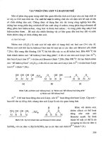
pin,
6,
and
the attached
ends of
the
levers,
and so
presses
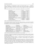
the
pawls
into the
ratchets and
stops
the
descent
of
the
plat-
form.
MECHANICAL
MOVEMENTS.
279
282
280
281
281
285
2SG
281
MECHANICAL MOVEMENTS.
279.
Crank
and slotted
cross-head,
with
Clayton's
sliding journal-box
applied
to the
crank-
wrist.
This box
consists of two
ta-
per lining
pieces
and two
taper
gibs adjust-
able
by
screws,
which
serve at the same
time
to
tighten
the box
on
the
wrist and
to
set
it
out to the slot
in the
cross-head as the
box
and wrist wear.
280.
A mode
of
working
a
windlass.
By
the
alternating
motion of
the
long
hand-
lever
to the
right,
motion
is
communicated
to the
short"
lever,
the end
of which is
in
immediate
contact
with the rim
of
the
wheel.
The
short
lever
has
a
very
limited
motion
upon
a
pin,
which is fixed
in
a block
of
cast-iron,
which
is
made
with two
jaws,
each
having
a
flange
projecting
inward in
contact
with the
inner surface
of
the
rim
of
the
wheel.
By
the
upward
motion
of
the
outward
end of the
short
lever,
the
rim
of
the wheel
is
jammed
between the end of the
lever
and the
flanges
of
the
block,
so as to
cause
friction sufficient to turn the wheel
by
the
further
upward
movement
of
the lever.
The
backward movement
of
the wheel
is
prevented by
a common ratchet-wheel and
pawls
;
as the short lever
is
pushed
down it
frees the
wheel and slides
freely
over
it.
281.
The revolution
of
the disk causes
the
lever
at the
right
to vibrate
by
the
pin
mov-
ing
in
the
groove
in the face of the disk.
282.
By
the revolution of
the
disk in
which
is fixed a
pin
working
in a
slot
in the
upright
bar
which turns on
a centei near the
bottom,
both ends
of the bar are made to
traverse,
the
toothed sector
producing
alternate
recti-
linear
motion in
the horizontal
bar at the
bottom,
and also
alternate
perpendicular
motion of
the
weight.
283.
By
a
vibratory
motion of
the
handle,
motion
is
communicated
by
the
pinion
to
the
racks. This is
used
in
working
small
air
pumps
for scientific
experiments.
284.
Represents
a
feeding
apparatus
for
the
bed of a
sawing
machine.
By
the revo-
lution of the crank
at
the lower
part
of
the
figure,
alternate motion
is
communicated to
the
horizontal
arm of
the bell crank
lever
whose fulcrum
is
at
a,
near
the
top
left-hand
corner of the
figure. By
this means
motion
is
communicated
to the
catch
attached
to
the
vertical
arm of the
lever,
and the said
catch
communicates
motion to
the
ratchet-wheel,
upon
the
shaft of which is
a toothed
pinion,
working
in the
rack attached
to
the
side of
the
carriage.
The feed
is
varied
by
a
screw
in
the bell-crank lever.
285.
Is the movable head of a
turning
lathe.
By turning
the
wheel to the
right,
motion
is communicated to
the
screw,
pro-
ducing
rectilinear motion
of
the
spindle
in
the end
of
which
the center
is
fixed.
286. Toe
and lifter for
working
puppet
valves
in steam
engines.
The
curved
toe
on the
rock-shaft
operates
on
the lifter
at-
tached
to the
lifting-rod
to raise
the
valve.
287.
Pickering's
governor.
The
balls
are
attached
to
springs
the
upper
end of each
of
which is attached
to
a collar fixed on
the
spindle,
and the lower end to a collar on the
sliding
sleeve.
The
springs yield
in
a
proper
degree
to the
centrifugal
force of the
balls,
and raise the sleeve
;
and as
the
centrifugal
force
diminishes,
they
draw the balls toward
the
spindle
and
depress
the sleeve.
MECHANICAL
MOVEMENTS.
288
MECHANICAL
MOVEMENTS.
73
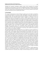
288
and
289.
The
former
is what is
termed a
recoil,
and the
latter a
repose
or dead-beat
escape-
ment
for
clocks.
The same
letters
of reference
indicate
like
parts
in both.
The
anchor,
H, L,
K,
is
caused,
by
the oscillation
of the
pendulum,
to
vibrate
upon
the
axis,
a. Between
the two ex-
tremities,
or
pallets,
H, K,
is
placed
the
escape-
wheel, A,
the
teeth
of which
come
alternately
against
the
outer
surface
of the
pallet,
K,
and in-
ner
surface
of
pallet,
H.
In
289
these
surfaces
are cut
to
a curve concentric
to the
axis,
a
;
con-
sequently,
during
the time
one of the
teeth
is
against
the
pallet
the wheel remains
perfectly
at
rest.
Hence the name
repose
or dead-beat.
In
288
the
surfaces
are of a differeent
form,
not
ne-
cessary
to
explain,
as it can be understood
that
any
form not concentric
with
the
axis, a,
must
produce
a
slight
recoil
of the wheel
during
the
escape
of the
tooth,
and hence
the
term
recoil es-
capement.
On the
pallets
leaving
teeth,
at each
oscillation
of the
pendulum,
the extremities
of
teeth
slide
along
the
surfaces, c, e,
and
d, b,
and
give
sufficient
impulse
to
pendulum.
290.
Another kind
of
pendulum escape-
ment.
291.
Arnold's chronometer
or free
escapement,
sometimes used in watches. A
spring,
A,
is fix-
ed or
screwed
against
the
plate
of the watch at b.
To the under side of this
spring
is
attached a
small
stop,
</,
against
which rest
successively
the
teeth
of
the
escape-wheel,
B
;
and on the
top
of
spring
is fixed a
stud, /',
holding
a
lighter
and
more
flexible
spring
which
passes
under a
hook,
k,
at the
extremity
of
A,
so that it
is free
on
being
depressed,
but in
rising
would
lift
A.
On the
axis of
the balance is a small
stud,
a,
which
touches the thin
spring
at each
oscillation
of bal-
ance-wheel. When the
movement
is in
the direc-
tion
shown
by
the
arrow,
the stud
depresses
the
spring
in
passing,
but
on
returning
raises
it and
the
spring,
A,
and
stop,
d,
and thus
allows one
tooth of
escape-wheel
to
pass, letting
them fall
immediately
to
arrest the
next.
At
the same
time,
that this
tooth
escapes
another
strikes
against
the side
of
the
notch,
g,
and restores to
I
balance-wheel
the force
lost
during
a
vibration.
It will be understood
that
only
at one
point
is the
I
free movement of balance
opposed
during
an os-
cillation.
292.
Stud
escapement,
used
in
large
clocks.
|
One
pallet,
B,
works
in front of
the
wheel and
the
other
at the
back.
The studs
are
arranged
in
the
.same
manner,
and rest
alternately
upon
the front or back
pallet.
As
the curve
of the
pallets
is an arc described
from
F,
this is a
repose
or dead-beat
escapement.
293. Duplex
escapement,
for
watches,
so
called
from
partaking
of
the
characters
of the
spur
and
crown wheels.
The
axis
of balance carries
pallet,
B,
which at
every
oscillation receives an
impulse
from the crown
teeth.
In
the
axis, A,
of
balance-
wheel is
cut
a notch into which
the teeth
round
the
edge
of
the wheel
successively
fall after each
one
of
the
crown
teeth
passes
the
impulse pallet,
B.
294
and
295.
A
cylinder
escapement.
294
shows the
cylinder
in
perspective,
and
295
shows
part
of the
escape-wheel
on a
large
scale,
and re-
presents
the
different
positions
taken
by cyl-
inder, A, B,
during
an oscillation. The
pallets,
a,
b,
c,
on the
wheel
rest
alternately
on the inside
and
outside of
cylinder.
To the
top
of
cylinder
is
attached the balance-wheel.
The
wheel
pallets
are beveled so as to
keep
up
the
impulse
of
bal-
ance
by
sliding against
the beveled
edge
of
cylin-
der.
296.
Lever
escapement.
The anchor
or
piece,
B,
which carries the
pallets,
is attached
to
lever,
E, C,
at one end
of which is
a
notch,
E. On a
disk secured
on
the arbor of
balance
is
fixed
a
small
pin
which enters
the notch
at
the
middle
of each
vibration,
causing
the
pallet
to enter
in
and retire from between
the teeth
of
escape-wheel
The wheel
gives
an
impulse
to each
of the
pallets
alternately
as it leaves a
tooth,
and
the lever
gives impulse
to
the balance-wheel
in
opposite
directions
alternately.
74
MECHANICAL MOVEMENTS.
297
299
300 301
302
303
301
MECHANICAL
MOVEMENTS.
75
297.
An
escapement
with a
lantern
wheel.
An
arm,
A,
carries
the
two
pallets,
B and
C.
298.
An
old-fashioned
watch
escapement.
299.
An old-fashioned
clock
escapement.
300
and
301.
A
clock
or watch
escape-
ment
;
300
being
a front
elevation,
and
301
a side
elevation. The
pallet
is
acted
upon
by
the
teeth
of
one
and
the
other
of
two
escape-wheels alternately.
face of
D,
are
concentric with the axis on
which the
pallets vibrate,
and
hence
there
is
no recoil.
304.
Pin-wheel
escapement,
somewhat
resembling
the
stud
escapement
shown
by
292.
The
pins,
A, B,
of the
escape-
wheel are
of two
different
forms,
but the
form
of
those
on
the
right
side
is the best.
One
advantage
of this
kind of
escapement
is
that
if one of the
pins
is
damaged
it
can
easily
be
replaced,
\vhereas
if a tooth
is
damaged
the
whole wheel
is ruined.
302.
Balance-wheel
escapement.
C
is the
305.
A
single-pin
pendulum
escapement,
balance
;
A, B,
are the
pallets
;
and
D is
|
The
escape-wheel
is
a
very
small
disk
with
the
escape-wheel.
single
eccentric
pin
;
it makes
half a revolu-
tion
for
every
beat of the
pendulum,
giving
the
impulse
on
the
upright
faces
of the
pal-
303.
A dead-beat
pendulum
escapement,
lets,
the
horizontal
faces of
which
are
dead
The
inner
face of the
pallet,
E,
and outer
!
ones.
This can also
be
adapted
to
watches.
7
6
MECHANICAL MOVEMENTS.
306 307
308
309
310
312
MECHANICAL
MOVEMENTS.
77
306.
Three-legged
pendulum
escapement.
The
pallets
are formed in
an
opening
in a
plate
attached to
the
pendulum,
and
the
three teeth of the
escape-wheel
operate
on
the
upper
and
lower
pallets
alternately.
One tooth
is shown in
operation
on
the
upper pallet.
307.
A
modification of
the
above with
long
stopping
teeth,
D
and
E,
A and B
are the
pallets.
308.
A
detached
pendulum
escapement,
leaving
the
pendulum,
P,
free or
detached
from the
escape-wheel,
except
at the
time of
receiving
the
impulse
and
unlocking
the
wheel.
There is
but
one
pallet,
I,
which
receives
impulse
only during
the
vibrations
of
the
pendulum
to
the
left. The
lever,
Q,
locks
the
escape-wheel
until
just
before
the
time for
giving
the
impulse,
when it is
un-
locked
by
the
click, C,
attached to
the
pen-
dulum. As
the
pendulum
returns
to
the
right,
the
click,
which
oscillates on
a
pivot,
will
be
pushed
aside
by
the
lever.
309.
Mudge's
gravity
escapement.
The
pallets, A,
B,
instead of
being
on
one
arbor,
are on
two,
as
shown
at
C.
The
pendulum
plays
between
the
fork-pins, P,
Q,
and
so
raises one of
the
weighted
pallets
out of the
wheel at each vibration.
When the
pendu-
lum
returns the
pallet
falls with
it,
and
the
weight
of
the
pallet
gives
the
impulse.
310.
Three-legged
gravity
escapement.
The
lifting
of
the
pallets,
A and
B,
is
done
by
the three
pins
near the
center of the
escape-wheel,
the
pallets
vibrating
from
two
centers near the
point
of
suspension
of
the
pendulum.
The
escape-wheel
is
locked
by-
means
of
stops,
D
and
E,
on the
pallets.
311.
Double
three-legged
gravity
escape-
ment.
Two
locking-wheels,
A,
B, C,
and
a,
6, c,
are here used with
one set of
lifting-
pins
between them.
The two
wheels
are
set
wide
enough
apart
to
allow
the
pallets
to lie
between
them.
The teeth of
the first-
mentioned
locking-wheel
are
stopped
by
a
stop-tooth,
D,
on
one
pallet,
and
those
of
the
other one
by
a
stop-tooth,
E,
on
the
other
pallet.
312.
Bloxam's
gravity escapement.
The
pallets
are lifted
alternately by
the small
wheel,
and
the
stopping
is
done
by
the ac-
tion
of
the
stops,
A
and
B,
on
the
larger
wheel. E
and F
are the
fork-pins
which
embrace
the
pendulum.
MECHANICAL
MOVEMENTS.
313