Basic Theory of Plates and Elastic Stability - Part 15 potx
Bạn đang xem bản rút gọn của tài liệu. Xem và tải ngay bản đầy đủ của tài liệu tại đây (407.36 KB, 34 trang )
Fang, S.J.; Roy, S. and Kramer, J. “Transmission Structures”
Structural Engineering Handbook
Ed. Chen Wai-Fah
Boca Raton: CRC Press LLC, 1999
TransmissionStructures
Shu-jinFang,SubirRoy,and
JacobKramer
Sargent&Lundy,Chicago,IL
15.1IntroductionandApplication
Application
•
StructureConfigurationandMaterial
•
Con-
structibility
•
MaintenanceConsiderations
•
StructureFami-
lies
•
StateoftheArtReview
15.2LoadsonTransmissionStructures
General
•
CalculationofLoadsUsingNESCCode
•
Calcula-
tionofLoadsUsingtheASCEGuide
•
SpecialLoads
•
Secu-
rityLoads
•
ConstructionandMaintenanceLoads
•
Loadson
Structure
•
VerticalLoads
•
TransverseLoads
•
Longitudinal
Loading
15.3DesignofSteelLatticeTower
TowerGeometry
•
AnalysisandDesignMethodology
•
Allow-
ableStresses
•
Connections
•
DetailingConsiderations
•
Tower
Testing
15.4TransmissionPoles
General
•
StressAnalysis
•
TubularSteelPoles
•
WoodPoles
•
ConcretePoles
•
GuyedPoles
15.5TransmissionTowerFoundations
GeotechnicalParameters
•
FoundationTypes—Selectionand
Design
•
Anchorage
•
ConstructionandOtherConsiderations
•
SafetyMarginsforFoundationDesign
•
FoundationMove-
ments
•
FoundationTesting
•
DesignExamples
15.6DefiningTerms
References
15.1 IntroductionandApplication
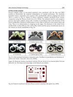
Transmissionstructuressupportthephaseconductorsandshieldwiresofatransmissionline.The
structurescommonlyusedontransmissionlinesareeitherlatticetypeorpoletypeandareshownin
Figure15.1.Latticestructuresareusuallycomposedofsteelanglesections.Polescanbewood,steel,
orconcrete.Eachstructuretypecanalsobeself-supportingorguyed.Structuresmayhaveoneof
thethreebasicconfigurations:horizontal,vertical,ordelta,dependingonthearrangementofthe
phaseconductors.
15.1.1 Application
Poletypestructuresaregenerallyusedforvoltagesof345-kVorless,whilelatticesteelstructurescan
beusedforthehighestofvoltagelevels.Woodpolestructurescanbeeconomicallyusedforrelatively
shorterspansandlowervoltages.Inareaswithsevereclimaticloadsand/oronhighervoltagelines
withmultiplesubconductorsperphase,designingwoodorconcretestructurestomeetthelarge
c
1999byCRCPressLLC
FIGURE 15.1: Transmission line structures.
loads can be uneconomical. In such cases, steel structures become the cost-effective option. Also,
if greater longitudinal loads are included in the design criteria to cover various unbalanced loading
contingencies, H-frame structures are less efficient at withstanding these loads. Steel lattice towers
can be designed efficiently for any mag nitude or orientation of load. The greater complexity of these
towers typically requires that full-scale load tests be performed on new tower t ypes and at least the
c
1999 by CRC Press LLC
tangent tower to ensure that all members and connections have been properly designed and detailed.
For guyed structures, it may be necessary to proof-test all anchors during construction to ensure that
they meet the required holding capacity.
15.1.2 Structure Configuration and Material
Structure cost usually accounts for 30 to 40% of the total cost of a transmission line. Therefore,
selecting an optimum structure becomes an integral part of a cost-effective transmission line design.
A structure study usually is performed to determine the most suitable structure configuration and
material based on cost, construction, and maintenance considerations and electric and magnetic field
effects. Some key factors to consider when evaluating the structure configuration are:
• A horizontal phase configuration usually results in the lowest structure cost.
• If right-of-way costs are high, or the width of the right-of-way is restricted or the line
closely parallels other lines, a vertical configuration may be lower in total cost.
• In addition to a wider right-of-way, horizontal configurations generally require more tree
clearing than vertical configurations.
• Although vertical configurations are narrower than horizontal configurations, they are
also taller, which may be objectionable from an aesthetic point of view.
• Where electric and magnetic field strength is a concern, the phase configuration is con-
sidered as a means of reducing these fields. In general, vertical configurations will have
lower field strengths at the edge of the right-of-way than horizontal configurations, and
delta configurations will have the lowest single-circuit field strengths and a double-circuit
with reverse or low-reactance phasing will have the lowest possible field strength.
Selection of the structure type and material depends on the design loads. For a single circuit
230-kV line, costs were estimated for single-pole and H-frame structures in wood, steel, and concrete
over a range of design span lengths. For this example, wood H-frames were found to have the lowest
installed cost, and a design span of 1000 ft resulted in the lowest cost per mile. As design loads and
other parameters change, the relative costs of the various structure types and materials change.
15.1.3 Constructibility
Accessibility for construction of the line should be considered when evaluating structure typ es.
Mountainous terrain or swampy conditions can make access difficult and use of helicopter may
become necessary. If permanent access roads are to be built to all structure locations for future
maintenance purposes, all sites will be accessible for construction.
To minimize environmental impacts, some lines are constructed without building permanent
access roads. Most construction equipment can traverse moderately swampy terrain by use of wide-
track vehicles or temporary mats. Transporting concrete for foundations to remote sites, however,
increases construction costs.
Steel lattice towers, which are typically set on concrete shaft foundations, would require the most
concrete at each tower site. Grillage foundations can also be used for these towers. However, the
cost of excavation, backfill and compaction for these foundations is often higher than the cost of a
drilled shaft. Unless subsurface conditions are poor, most pole structures can be directly embedded.
However, if unguyed pole structures are used at medium to large line angles, it may b e necessary to
use drilled shaft foundations.
Guyed structures can also create construction difficulties in that a wider area must be accessed at
each structure site to install the guys and anchors. Also, careful coordination is required to ensure
that all guys are tensioned equally and that the structure is plumb.
c
1999 by CRC Press LLC
Hauling the structure materials to the site must also be considered in evaluating constructibility.
Transporting concrete structures, which weigh at least five times as much as other types of structures,
will be difficult and will increase the construction cost of the line. Heavier equipment, more trips
to transport materials, and more matting or temporary roadwork will be required to handle these
heavy poles.
15.1.4 Maintenance Considerations
Maintenance of the line is generally a function of the structure material. Steel and concrete structures
should require very little maintenance, although the maintenance requirements for steel structures
depends on the type of finish applied. Tubular steel structures are usually galvanized or made of
weathering steel. Lattice structures are galvanized. Galvanized or painted structures require periodic
inspection and touch-up or reapplication of the finish while weathering steel structures should
have relatively low maintenance. Wood structures, however, require more frequent and thorough
inspections to evaluate the condition of the poles. Wood structures would also generally require
more frequent repair and/or replacement than steel or concrete structures. If the line is in a remote
location and lacks permanent access roads, this can be an important consideration in selecting
structure material.
15.1.5 Structure Families
Once the basic structure type has been established, a family of structures is designed, based on
the line route and the type of terrain it crosses, to accommodate the various loading conditions as
economically as possible. The structures consist of tangent, angle, and deadend structures.
Tangent structures are used when the line is straight or has a very small line angle, usually not
exceeding 3
◦
. The line angle is defined as the deflection angle of the line into adjacent spans. Usually
one tangent type design is sufficient where terrain is flat and the span lengths are approximately equal.
However, in rolling and mountainousterrain, spans can vary greatly. Some spans, for example, across
a long valley, may be considerably larger than the normal span. In such cases, a second tangent design
for long spans may prove to be more economical. Tangent structures usually comprise 80 to 90% of
the structures in a transmission line.
Angle towers are used where the line changes direction. T he point at which the direction change
occurs is generally referred to as the pointofintersection (P.I.)location. Angle towers are placed at the
P.I. locations such that the transverse axis of the cross arm bisects the angle formed by the conductor,
thus equalizing the longitudinal pulls of the conductors in the adjacent spans. On lines where large
numbers of P.I. locations occur with varying degrees of line angles, it may prove economical to have
more than one angle structure design: one for smaller angles and the other for larger angles.
When the line angle exceeds 30
◦
, the usual practice is to use a deadend type design. Deadend
structures are designed to resist wire pulls on one side. In addition to their use for large angles, the
deadendstructuresareusedas terminalstructuresorfor sectionalizingalong line consistingof tangent
structures. Sectionalizing provides a longitudinal strength to the line and is generally recommended
every 10 miles. Deadend structures may also be used for resisting uplift loads. Alternately, a separate
strain structure design with deadend insulator assemblies may prove to be more economical when
there is a large number of structures with small line angle subjected to uplift. These structures are
not required to resist the deadend wire pull on one side.
15.1.6 State of the Art Review
A major development in the last 20 years has been in the area of new analysis and design tools.
These include software packages and design guidelines [12, 6, 3, 21, 17, 14, 9, 8], which have greatly
c
1999 by CRC Press LLC
improved design efficiency and have resulted in more economical structures. A number of these
tools have been developed based on test results, and many new tests are ongoing in an effort to refine
the current procedures. Another area is the development of the reliability based design concept [6].
This methodology offers a uniform procedure in the industry for calculation of structure loads and
strength, and provides a quantified measure of reliability for the design of various transmission line
components.
Aside from continued refinements in design and analysis, significant progress has been made in the
manufacturing technology in the last two decades. The advance in this area has led to the increasing
usage of cold formed shapes, structures with mixed construction such as steel poles with lattice arms
or steel towers with FRP components, and prestressed concrete poles [7].
15.2 Loads on Transmission Structures
15.2.1 General
Prevailing practice and most state laws require that transmission lines be designed, as a minimum,
to meet the requirements of the current edition of the National Electrical Safety Code (NESC) [5].
NESC’s rules for the selection of loads and overload capacity factors are specified to establish a
minimum acceptable level of safety. The ASCE Guide for Electrical Transmission Line Structural
Loading (ASCE Guide) [6] provides loading guidelines for extreme ice and wind loads as well as
security and safety loads. These guidelines use reliability based procedures and allow the design of
transmission line structures to incorporate specified levels of reliability depending on the importance
of the structure.
15.2.2 Calculation of Loads Using NESC Code
NESC code [5] recognizes three loading districts for ice and wind loads which are designated as
heavy, medium, and light loading. The radial thickness of ice and the wind pressures specified for
the loading distr icts are shown in Table 15.1. Ice build-up is considered only on conductors and
shield wires, and is usually ignored on the structure. Ice is assumed to weigh 57 lb/ft
3
. The wind
pressure applies to cylindrical surfaces such as conductors. On the flat surface of a lattice tower
member, the wind pressure values are multiplied by a force coefficient of 1.6. Wind force is applied
on both the windward and leeward faces of a lattice tower.
TABLE 15.1 Ice, Wind, and Temperature
Loading districts
Heavy Medium Light
Radial thickness
of ice (in.) 0.50 0.25 0
Horizontal wind
pressure (lb/ft
2
)4 4 9
Temperature (
◦
F) 0 +15 +30
NESC also requires structures to be designed for extreme wind loading corresponding to 50 year
fastest mile wind speed with no ice loads considered. This provision applies to all structures without
conductors, and structures over 60 ft supporting conductors. The extreme wind speed varies from a
basic speed of 70 mph to 110 mph in the coastal areas.
In addition, NESC requires that the basic loads be multiplied by overload capacity factors to
c
1999 by CRC Press LLC
determine the design loads on structures. Overload capacity factors make it possible to assign relative
importance to the loads instead of using various allowable stresses for different load conditions.
Overload capacity factors specified in NESC have a larger value for wood structures than those for
steel and prestressed concrete structures. This is due to the wide variation found in wood strengths
andthe agingeffect of wood caused bydecayand insectdamage. In the1990edition, NESCintroduced
an alternative method, where the same overload factors are used for all the materials but a strength
reductionfactorisusedforwood.
15.2.3 Calculation of Loads Using the ASCE Guide
The ASCE Guide [6] specifies extreme ice and extreme wind loads, based on a 50-year return period,
which are assigned a reliability factor of 1. These loads can be increased if an engineer wants to use
a higher reliability factor for an important line, for example a long line, or a line which provides the
only source of load. The load factors used to increase the ASCE loads for different reliability factors
are given in Table 15.2.
TABLE15.2 Load Factor to Adjust Line Reliability
Line reliability factor, LRF 1 2 4 8
Load return period, RP 50 100 200 400
Corresponding load factor,
˜a 1.0 1.15 1.3 1.4
In calculating wind loads, the effects of terrain, structure height, wind gust, and structure shape
are included. These effects are explained in detail in the ASCE Guide. ASCE also recommends that
the ice loads be combined with a wind load equal to 40% of the extreme wind load.
15.2.4 Special Loads
In addition to the weather related loads, transmission line structures are designed for special loads
that consider security and safety aspects of the line. These include security loads for preventing
cascading type failures of the structures and construction and maintenance loads that are related to
personnel safety.
15.2.5 Security Loads
Longitudinal loads may occur on the structures due to accidental events such as broken conductors,
broken insulators, or collapse of an adjacent structure in the line due to an environmental event
such as a tornado. Regardless of the triggering event, it is important that a line support structure
be designed for a suitable longitudinal loading condition to provide adequate resistance against
cascading t ype failures in which a larger number of structures fail sequentially in the longitudinal
direction or parallel to the line. For this reason, longitudinal loadings are sometimes referred to as
“anticascading”, “failure containment”, or “security loads”.
There are two basic methods for reducing the risk of cascading failures, depending on the type of
structure, and on local conditions and practices. These methods are: (1) design all structures for
broken wire loads and (2) install stop structures or guys at specified intervals.
Design for Broken Conductors
Certain types of structures such as square-based lattice towers, 4-guyed structures, and sing le
shaft steel poles have inherent longitudinal strength. For lines using these types of structures, the
c
1999 by CRC Press LLC
recommended practice is to design every structure for one broken conductor. This provides the
additional longitudinal strength for preventing cascading failures at a relatively low cost.
Anchor Structures
When single pole wood structures or H-frame structures having low longitudinal strength are
used on a line, designing every structure for longitudinal strength can be ver y expensive. In such
cases, stop or anchor str uctures with adequate longitudinal strength are provided at specific intervals
to limit the cascading effect. The Rural Electrification Administration [19] recommends a maximum
interval of 5 to 10 miles between structures with adequate longitudinal capacit y.
15.2.6 Construction and Maintenance Loads
Construction andmaintenance(C&M) loadsare, toa largeextent, controllableand are directly related
to construction and maintenance methods. A detailed discussion on these types of loads is included
in the ASCE Loading Guide, and Occupation Safety and Health Act (OSHA) documents. It should
be emphasized, however, that workers can be seriously injured as a result of structure overstress
during C&M operations; therefore, personnel safety should be a paramount factor when establishing
C&M loads. Accordingly, the ASCE Loading Guide recommends that the specified C&M loads be
multiplied by a minimum load factor of 1.5 in cases where the loads are “static” and well defined;
and by a load factor of 2.0 when the loads are “dynamic”, such as those associated with moving wires
during stringing operations.
15.2.7 Loads on Structure
Loads are calculated on the structures in three directions: vertical, transverse, and longitudinal. The
transverse load is perpendicular to the line and the longitudinal loads act parallel to the line.
15.2.8 Vertical Loads
The vertical load on supporting structures consists of the weight of the structure plus the superim-
posed weight, including all wires, ice coated where specified.
Vertical load of wire V
w
in. (lb/ft) is given by the following equations:
V
w
= wt. of bare wire (lb/f t) + 1.24(d +I)I (15.1)
where
d = diameter of wire (in.)
I = ice thickness (in.)
Vertical wire load on structure (lb)
= Vw× vertical design span × load factor
(15.2)
Vertical design span is the distance between low points of adjacent spans and is indicated
in Figure 15.2.
15.2.9 Transverse Loads
Transverse loads are caused by wind pressure on wires and structure, and the transverse component
of the line tension at angles.
c
1999 by CRC Press LLC
FIGURE 15.2: Vertical and horizontal design spans.
Wind Load on Wires
The transverse load due to wind on the wire is given by the following equations:
W
h
= p × d/12 × Horizontal Span × OCF (without ice) (15.3)
= p × (d + 2I)/12 × Horizontal Span × OCF (with ice) (15.4)
where
W
h
= transverse wind load on wire in lb
p = wind pressure in lb/ft
2
d = diameter of wire in in.
I = radial thickness of ice in in.
OCF = Overload Capacity Factor
Horizontal span is the distance between midpoints of adjacent spans and is shown in Figure 15.2.
Transverse Load Due to Line Angle
Where a line changes direction, the total transverse load on the structure is the sum of the
transverse wind load and the transverse component of the wire tension. The transverse component
of the tension may be of significant magnitude, especially for large angle structures. To calculate the
total load, a wind direction should be used which will give the maximum resultant load considering
the effects on the wires and structure.
The transverse component of wire tension on the structure is given by the following equation:
H = 2T sin θ/2
(15.5)
where
H = transverse load due to wire tension in pounds
T = wire tension in pounds
θ = Line angle in degrees
Wind Load on Structures
In addition to the wire load, structures are subjected to wind loads acting on the exposed areas
of the structure. The wind force coefficients on lattice towers depend on shapes of member sections,
solidity ratio, angle of incidence of wind (face-on wind or diagonal w ind), and shielding. Methods
c
1999 by CRC Press LLC
for calculating wind loads on transmission structures are given in the ASCE Guide as well the NESC
code.
15.2.10 Longitudinal Loading
There are several conditions under which a structure is subjected to longitudinal loading:
Deadend Str uctures—These structures are capable of withstanding the full tension of the conductors
and shield wires or combinations thereof, on one side of the structure.
Stringing— Longitudinal load may occur at any one phase or shield wire due to a hang-up in the
blocks during stringing. The longitudinal load istaken as the stringing tension forthe complete phase
(i.e., all subconductors strung simultaneously) or a shield wire. In order to avoid any prestressing of
the conductors, stringing tension is typically limited to the minimum tension required to keep the
conductor from touching the ground or any obstr uctions. Based on common practice and according
to the IEEE “Guide to the Installation of Overhead Transmission Line Conductors” [4], stringing
tension is generally about one-half of the sagging tension. Therefore, the longitudinal stringing load
is equal to 50% of the initial, unloaded tension at 60
◦
F.
Longitudinal Unbalanced Load—Longitudinal unbalanced forces can develop at the structures due
to various conditions on the line. In rugged terrain, large differentials in adjacent span lengths,
combined with inclined spans, could result in significant longitudinal unbalanced load under ice and
wind conditions. Non-uniform loading of adjacent spans can also produce longitudinal unbalanced
loads. This loadis based on an ice shedding condition where ice is dropped from one span and not the
adjacent spans. Reference [12] includes a software that is commonly used for calculating unbalanced
loads on the structure.
EXAMPLE 15.1: Problem
Determine the wire loads on a small angle structure in accordance with the data given below. Use
NESC medium district loading and assume all intact conditions.
Given Data:
Conductor: 954 kcm 45/7 ACSR
Diameter = 1.165 in.
Weight = 1.075 lb/ft
Wire tension for NESC medium loading = 8020 lb
Shield Wire: 3 No.6 Alumoweld
Diameter = 0.349 in.
Weight = 0.1781 lb/ft
Wire tension for NESC medium loading = 2400 lb
Wind Span = 1500 ft
Weight Span = 1800 ft
Line angle = 5
◦
Insulator weight = 170 lb
c
1999 by CRC Press LLC
Solution
NESC Medium District Loading
4 psf wind, 1/4-in. ice
Ground Wire Iced Diameter = 0.349 + 2 ×0.25 = 0.849 in.
Conductor Ice Diameter = 1.165 +2 ×0.25 = 1.665 in.
Overload Capacity Factors for Steel
Transverse Wind = 2.5
Wire Tension = 1.65
Vertical = 1.5
Conductor Loads On Tower
Transverse
Wind = 4 psf ×1.665"/12 ×1500 ×2.5 = 2080 lb
Line Angle = 2 × 8020 × sin 2.5
◦
× 1.65 = 1150 lb
Total = 3230 lb
Vert ical
Bare Wire = 1.075 × 1800 ×1.5 = 2910 lb
Ice ={1.24(d + I)I}1800 ×1.5 = 1.24(1.165 +.25).25
× 1800 × 1.5 = 1185 lb
Insulator = 170 ×1.5 = 255 lb
Total = 4350 lb
Ground Wire Loads on Tower
Transverse
Wind = 4 psf ×0.849/12 ×1500 ×2.5 = 1060 lb
Line Angle = 2 × 2400 × sin 2.5 × 1.65 = 350 lb
Total = 1410 lb
15.3 Design of Steel Lattice Tower
15.3.1 Tower Geometry
A typical sing le circuit, horizontal configuration, self-supported lattice tower is shown in Figure 15.3.
The design of a steel lattice tower begins with the development of a conceptual design, which estab-
lishes thegeometry of the structure. In developingthe geometry,structure dimensions are established
for the tower window, crossarms and bridge, shield wire peak, bracing panels, and the slope of the
c
1999 by CRC Press LLC
FIGURE 15.3: Single circuit lattice tower.
tower leg below the waist. The most important criteria for determining structure geometry are the
minimum phase to phase and phase to steel clearance requirements, which are functions of the line
voltage. Spacing of phase conductors may sometimes be dictated by conductor galloping considera-
tions. Height of the tower p eak above the crossarm is based on shielding considerations for lightning
protection. The width of the tower base depends on the slope of the tower leg below the waist . The
overall structure height is governed by the span length of the conductors between structures.
The lattice tower is made up of a basic body, body extension, and leg extensions. Standard designs
are developed for these components for a given tower type. The basic body is used for all the towers
regardless of the height. Body and leg extensions are added to the basic body to achieve the desired
tower height.
The primary members of a tower are the leg and the bracing members which carry the vertical
and shear loads on the tower and transfer them to the foundation. Secondary or redundant bracing
members are used to provide intermediate support to the primary members to reduce their unbraced
length and increase their load carrying capacity. The slope of the tower leg from the waist down has
a significant influence on the tower weight and should be optimized to achieve an economical tower
c
1999 by CRC Press LLC
design. A flatter slope results in a wider tower base which reduces the leg size and the foundation
size, but will increase the size of the bracing. Typical leg slopes used for towers range from 3/4 in. 12
for light tangent towers to 2 1/2 in. 12 for heavy deadend towers.
The minimum included angle ∞ between two intersecting members is an important factor for
proper force distribution. Reference [3] recommends a minimum included angle of 15
◦
, intended
to develop a truss action for load transfer and to minimize moment in the member. However, as the
tower loads increase, the preferred practice is to increase the included angle to 20
◦
for angle towers
and 25
◦
for deadend towers [23].
Bracing members below the waist can be designed as a tension only or tension compression system
as shown in Figure 15.4. In a tension only system shown in (a), the bracing members are designed
FIGURE 15.4: Bracing systems.
to carry tension forces only, the compression forces being carried by the horizontal strut. In a
tension/compression system shown in (b) and (c), the braces are designed to carry both tension and
compression. A tension only system may prove to be economical for lighter tangent towers. But for
heavier towers, a tension/compression system is recommended as it distributes the load equally to
the tower legs.
A staggered bracing pattern is sometimes used on the adjacent faces of a tower for ease of connec-
tions and to reduce the number of bolt holes at a section. Tests [23] have shown that staggering of
main bracing membersmay producesignificant momentin the membersespecially for heavily loaded
towers. For heavily loaded towers, the preferred method is to stagger redundant bracing members
and connect the main bracing members on the adjacent faces at a common panel point.
15.3.2 Analysis and Design Methodology
The ASCE Guide for Design of Steel Transmission Towers [3] is the industry document governing the
analysis and design of lattice steel towers. A lattice tower is analyzed as a space truss. Each member of
the tower is assumed pin-connected at itsjoints carrying only axial loadand no moment. Today, finite
element computer programs [12, 21, 17] are the typical tools for the analysis of towers for ultimate
design loads. In the analytical model the tower geometry is broken down into a discrete number
of joints (nodes) and members (elements). User input consists of nodal coordinates, member end
incidences and properties, and the tower loads. For symmetric towers, most programs can generate
the complete geometry from a part of the input. Loads applied on the tower are ultimate loads which
include overload capacity factors discussed in Section 15.2. Tower members are then designed to
c
1999 by CRC Press LLC
the yield strength or the buckling strength of the member. Tower members typically consist of steel
angle sections, which allow ease of connection. Both single- and double-angle sections are used.
Aluminum towers are seldom used today due to the high cost of aluminum. Steel types commonly
used on towers are ASTM A-36 (F y = 36 ksi) or A-572 (F y = 50 ksi). The most common finish
for steel towers is hot-dipped galvanizing. Self-weathering steel is no longer used for towers due to
the “pack-out” problems experienced in the past resulting in damaged connections.
Tower members are designed to carry axial compressive and tensile forces. Allowable stress in
compression is usually governed by buckling, which causes the member to fail at a stress well below
the yield strength of the material. Buckling of a member occurs about its weakest axis, which for
a single angle section is at an inclination to the geometric axes. As the unsupported length of the
member increases, the allowable stress in buckling is reduced.
Allowable stress in a tension member is the full yield stress of the material and does not depend
on the member length. The st ress is resisted by a net cross-section, the area of which is the gross
area minus the area of the bolt holes at a given section. Tension capacity of an angle member may
be affected by the type of end connection [3]. For example, when one leg of the angle is connected,
the tension capacity is reduced by 10%. A further reduction takes place when only the short leg of
an unequal angle is connected.
15.3.3 Allowable Stresses
Compression Member
The allowable compressive stress in buckling on the gross cross-sectional area of axially loaded
compression members is given by the following equations [3]:
Fa =
1 − (KL/R)
2
/(2Cc
2
)
Fy if KL/R = Cc or less (15.6)
Fa = 286000/(kl/r)
2
if KL/R > Cc (15.7)
Cc = (3.14)(2E/Fy)
1/2
(15.8)
where
Fa = allowable compressive stress (ksi)
Fy = yield strength (ksi)
E = modulus of elasticity (ksi)
L/R = maximum slenderness ratio = unbraced length /radius of gyration
K = effective length co-efficient
The angle member must also be checked for local buckling considerations. If the ratio of the
angle effective width to angle thickness (w/t) exceeds 80/(Fy)
1/2
, the value of Fa will be reduced
in accordance with the provisions of Reference [3].
The above formulas indicate that the allowable buckling stress is largely dependent on the effective
slenderness ratio (kl/r) and the material yield strength (F y). It may be noted, however, that Fy
influences the buckling capacity for short members only (kl/r < Cc). For long members (kl/r >
Cc), the allowable buckling stress is unaffected by the material strength.
The slenderness ratio is calculated for different axes of buckling and the maximum value is used
for the calculation of allowable buckling stress. In some cases, a compression member may have an
intermediate lateral support in one plane only. This support prevents weak axisand in-plane buckling
but not the out-of-plane buckling. In such cases, the slenderness ratio in the member geometric axis
will be greater than in the member weak axis, and will control the design of the member.
The effective length coefficient K adjusts the member slenderness ratio for different conditions
of framing eccentricity and the restraint against rotation provided at the connection. Values of K
c
1999 by CRC Press LLC
for six different end conditions, curves one through six, have been defined in Reference [3]. This
reference also specifies maximum slenderness ratios of tower members, which are as follows:
Type of Member Maximum KL/R
Leg 150
Bracing 200
Redundant 250
Tests have shown that members with very low L/R are subjected to substantial bending moment in
addition to axial load. This is especially true for heavily loaded towers where members are relatively
stiff and multiple bolted rigid joints are used [22]. A minimum L/R of 50 is recommended for
compression members.
Tension Members
The allowable tensile force on the net cross-sectional area of a member is given by the following
equation [3]:
P
t
= Fy · An · K (15.9)
where
P
t
= allowable tensile force (kips)
Fy = yield strength of the material (ksi)
An = net cross-sectional area of theangle after deductingfor bolt holes(in.
2
). Forunequal angles,
if the short leg is connected, An is calculated by considering the unconnected leg to be the
same size as the connected leg
K = 1.0 if both legs of the angle connected
= 0.9 if one leg connected
The allowable tensile force must also meet the block shear criteria at the connection in accordance
with the provisions of Reference [3].
Although the allowable force in a tension member does not depend on the member length, Refer-
ence [3]specifies a maximum L/R of 375for these members. This limit minimizes member vibration
under everyday steady state wind, and reduces the risk of fatigue in the connection.
15.3.4 Connections
Transmission towers typically use bearing type bolted connections. Commonly used bolt sizes are
5/8", 3/4", and 7/8" in diameter. Bolts are tightened to a snug tight condition with torque values
ranging from 80 to 120 ft-lb. These torques are much smaller than the torque used in friction type
connections in steel buildings. The snug tight torque ensures that the bolts will not slip back and
forth under everyday wind loads thus minimizing the risk of fatigue in the connection. Under full
design loads, the bolts would slip adding flexibility to the joint, which is consistent with the truss
assumption.
Load carrying capacity of the bolted connections depends on the shear strength of the bolt and the
bearing strength of the connected plate. The most commonly used bolt for transmission towers is
A-394, Type 0 bolt with an allowable shear stress of 55.2 ksi across the threaded part. The maximum
allowable stress in bearing is 1.5 times the minimum tensile strength of the connected part or the
bolt. Use of the maximum bearing stress requires that the edge distance from the center of the bolt
hole to the edge of the connected part be checked in accordance with the provisions of Reference [3].
c
1999 by CRC Press LLC
15.3.5 Detailing Considerations
Bolted connections are detailed to minimize eccentricity as much as possible. Eccentric connections
give r ise to a bending moment causing additional shear force in the bolts. Sometimes small eccen-
tricities may be unavoidable and should be accounted for in the design. The detailing specification
should clearly specify the acceptable conditions of eccentricity.
Figure 15.5 shows two connections, one with no eccentricity and the second with a small eccen-
tricity. In the first case the lines of force passing through the center of gravity (c.g.) of the members
FIGURE 15.5: Brace details.
intersect at a common point. This is the most desired condition producing no eccentricity. In the
second case, thelines of force of thetwo bracing members do not intersect with that ofthe leg member
thus producing an eccentricity in the connection. It is common practice to accept a small eccentricity
as long as the intersection of the lines of force of the bracing members does not fall outside the width
of the leg member. In some cases it may be necessary to add gusset plates to avoid large eccentricities.
In detailing double angle members, care should be taken to avoid a large gap between the angles
that are typically attached together by stitch bolts at specified intervals. Tests [23] have shown that
a double angle member with a large gap between the angles does not act as a composite member.
This results in one of the two angles carrying significantly more load than the other angle. It is
recommended that the gap between the two angles of a double angle member be limited to 1/2 in.
The minimum size of a member is sometimes dictated by the size of the bolt on the connected leg.
The minimum width of members that can accommodate a single row of bolts is as follows:
Bolt diameter Minimum width of member
5/8" 1 3/4"
3/4" 2"
7/8" 2 1/2"
Tension members are detailed with draw to facilitate erection. Members 15 ft in length, or less, are
detailed 1/8 in. short, plus 1/16 in. for each additional 10 ft. Tension members should have at least
two bolts on one end to facilitate the draw.
15.3.6 Tower Testing
Full scale load tests are conducted on new tower designs and at least the tangent tower to verify the
adequacy of the tower members and connections to withstand the design loads specified for that
structure. Towers are required to pass the tests at 100% of the ultimate design loads. Tower tests
c
1999 by CRC Press LLC
also provide insight into actual stress distribution in members, fit-up verification and action of the
structure in deflected positions. Detailed procedures of tower testing are given in Reference [3].
EXAMPLE 15.2:
Description
Check the adequacy of the following tower components shown in Figure 15.3.
Member 1 (compressive leg of the leg extension)
M e mber force = 132 kips (compression)
Angle size = L5 ×5 ×3/8"
F
y
= 50 ksi
Member 2 (tension member)
Tensile force = 22 kips
Angle size = L21/2 × 2 × 3/16 (long leg connected)
Fy = 36 ksi
Bolts at the splice connection of Member 1
Number of 5/8" bolts = 6 (Butt Splice)
Type of bolt = A-394, Type O
Solution
Member 1
M e mber force = 132 kips (compression)
Angle size = L5 ×5 ×3/8"
F
y
= 50 ksi
Find maximum L/R
Pr operties of L 5 ×5 ×3/8"
Area = 3.61 in.
2
r
x
= r
y
= 1.56 in.
r
z
= 0.99 in.
Member 1 has the same bracing pattern in adjacent planes. Thus, the unsupported length is the same
in the weak (z − z) axis and the geometric axes (x − x and y − y).
l
z
= l
x
= l
y
= 61"
Maximum L/R = 61/0.99 = 61.6
Allowable Compressive Stress:
Using Curve 1 for leg member (no framing eccentricity), per Reference [3], k = 1.0
KL/R = L/R = 61.6
c
1999 by CRC Press LLC
Cc = (3.14)(2E/Fy)
1/2
= (3.14)(2 ×29000/50)
1/2
= 107.0 which is > KL/R
Fa =
1 − (KL/R)
2
/(2Cc
2
)
Fy
=
1 − (61.6)
2
/(2 ×107.0
2
)
50.0
= 41.7 ksi
Allowable compressive load = 41.7 ksi × 3.61 in.
= 150.6 kips > 132 kips → O.K.
Check local buckling:
w/t = (5.0 − 7/8)/(3/8) = 11.0
80/(Fy)
1/2
= 80/(50)
1/2
= 11.3 > 11.0 O.K.
Member 2
Tensile force = 22 kips
Angle size = L 2 − 1/2 × 2 ×3/16
Area = 0.81 in.
2
Fy = 36 ksi
Find tension capacity
P
t
= Fy · An · K
Diameter of bolt hole = 5/8" +1/16" = 11/16"
Assuming one bolt hole deduction in 2 − 1/2" leg width,
Area of bolt hole = angle th. × hole diam.
= (3/16)(11/16) = 0.128 in.
2
An = gross area − bolt hole area
= 0.81 −0.128 = 0.68 in.
2
K = 0.9, since member end is connected by one leg
P
t
= (36)(0.68)(0.9) = 22.1 kips > 22.0 kips, O.K.
Bolts for Member 1
Number of 5/8" bolts = 6 (Butt Splice)
Type of bolt = A-394, Type O
Shear Strength Fv = 55.2 ksi
Root area thru threads = 0.202 in.
2
c
1999 by CRC Press LLC
Shear capacity of bolts:
Bolts act in double shear at butt splice
Shear capacity of 6 bolts in double shear
= 2 × (Root area) × 55.2 ksi ×6
= 133.8 kips > 132 kips ⇒ O.K.
Bearing capacity of connected part:
Thickness of connected angle = 3/8"
F
y
of angle = 50 ksi
Capacity of bolt in bearing
= 1.5 ×Fu× th. of angle × dia. of bolt
Fuof 50 ksi material = 65 ksi
Capacity of 6 bolts in bearing = 1.5 × 65 ×3/8 ×5/8 ×6
= 137.1 kips > 132 kips, O.K.
15.4 Transmission Poles
15.4.1 General
Transmission poles made of wood, steel, or concrete are used on transmission lines at voltages up to
345-kv. Wood poles can be economically used for relatively shor ter spans and lower voltages whereas
steel poles and concrete poles have greater strength and are used for higher voltages. For areas where
severe climatic loads are encountered, steel poles are often the most cost-effective choice.
Pole structures have two basic configurations: single pole and H-frame (Figure 15.1). Single pole
structures are used for lower voltages and shorter spans. H-frame structures consist of two poles
connected by a framing comprised of the cross arm, the V-braces, and the X-braces. The use of
X-braces significantly increases the load carrying capacity of H-frame structures.
Atlineanglesor deadendconditions,guying isusedtodecrease pole deflectionsandto increasetheir
transverse or longitudinal structural strength. Guys also help prevent uplift on H-frame structures.
Large deflections would be a hindrance in stringing operations.
15.4.2 Stress Analysis
Transmission poles are flexible structures and may undergo relatively large lateral deflections under
design loads. A secondary moment (or P − effect) will develop in the poles due to the lateral
deflections at the load points. This secondary moment can be a significant percent of the total
moment. In addition, large deflections of poles can affect the magnitude and direction of loads
caused by the line tension and stringing operations. Therefore, the effects of pole deflections should
be included in the analysis and design of single and multi-pole transmission structures.
To properly analyze and design transmission structures, the standard industry practice today is to
usenonlinear finite e lement computerprograms. Thesecomputerprograms allowefficientevaluation
of pole structures considering geometric and/or material nonlinearities. For wood poles, there are
several popular computer software programs available from EPRI [15]. They are specially developed
for design and analysis of wood pole structures. Other general purpose commercial programs auch
as SAP-90 and STAAD [20, 10] are available for performing small displacement P − analysis.
c
1999 by CRC Press LLC
15.4.3 Tubular Steel Poles
Steel transmission poles are fabricated from uniformly tapered hollow steel sections. The cross-
sections of the poles vary from round to 16-sided polygonal with the 12-sided dodecagonal as the
most common shape. The p oles are formed into design cross-sections by braking, rolling, or stretch
bending.
For these structures the usual industry practice is that the analysis, design, and detailing are
performed by thesteel polesupplier. This facilitatesthe design to b e more compatible with fabrication
practice and available equipment.
Design of tubular steel poles is governed by the ASCE Manual # 72 [9]. The Manual provides
detailed design criteria including allowable stresses for pole masts and connections and stability
considerations for global and localbuckling. It alsodefines the requirements for fabrication, erection,
load testing, and quality assurance.
It should be noted that steel transmission pole structures have several unique design features
as compared to other tubular steel str uctures. First, they are designed for ultimate, or maximum
anticipated loads. Thus, stress limits of the Manual #72 are not established for working loads but for
ultimate loads.
Second, Manual #72 requires that stability be provided for the structure as a whole and for each
structural element. In other words, the effects of deflected structural shape on structural stability
should be considered in the evaluation of the whole structure as well as the individual element. It
relies on the use of the large displacement nonlinear computer analysis to account for the P − effect
and check for stability. To prevent excessive deflection effects, the lateral deflection under factored
loads is usually limited to 5 to 10% of the pole height. Pre-cambering of poles may be used to help
meet the imposed deflection limitation on angle structures.
Lastly, due to its polygonal cross-sections combined with thin material, special considerations
must be given to calculation of member section properties and assessment of local buckling.
To ensure a polygonal tubular member can reach yielding on its extreme fibers under combined
axial and bending compression, local buckling must be prevented. This can be met by limiting the
width to thickness ratio, w/t,to240/(F y)
1/2
for tubes with 12 or fewer sides and 215/(F y)
1/2
for
hexdecagonal tubes. If the axial stress is 1 ksi or less, the w/t limit may be increased to 260/(Fy)
1/2
for tubes with 8 or fewer sides [9].
Special considerations should be given in the selection of the pole materials where poles are to
be subjected to subzero temperatures. To mitigate potential brittle fracture, use of steel with good
impact toughness in the longitudinal direction of the pole is necessary. Since the majority of pole
structures are manufactured from steels of a yield strength of 50to 65 ksi (i.e., ASTM A871 and A572),
it is advantageous to specify a minimum Charpy-V-notch impact energy of 15 ft-lb at 0
◦
F for plate
thickness of 1/2 in. or less and 15 ft-lb at −20
◦
F for thicker plates. Likewise, high strength anchor
bolts made of ASTM A615-87 Gr.75 steel should have a minimum Charpy V-notch of 15 ft-lbs at
−20
◦
F.
Corrosion protection must be considered for steel poles. Selection of a specific coating or use
of weathering steel depends on weather exposure, past experience, appearance, and economics.
Weathering steel is best suited for environments involving proper wetting and drying cycles. Surfaces
that are wet for prolonged periods will corrode at a rapid rate. A protective coating is required when
such conditions exist. When weathering steel is used, poles should also be detailed to provide good
drainage and avoid water retention. Also, poles should either be sealed or well ventilated to assure
the proper protection of the interior surface of the pole. Hot-dip galvanizing is an excellent alternate
means for corrosion protection of steel poles above grade. Galvanized coating should comply with
ASTM A123 for its overall quality and for weight/thickness requirements.
Pole sections are normally joined by telescoping or slip splices to transfer shears and moments.
They are detailed to have a lap length no less than 1.5 times the largest inside diameter. It is important
c
1999 by CRC Press LLC
to have a tight fit in slip joint to allow load transfer by friction between sections. Locking devices or
flanged joints will be needed if the splice is subjected to uplift forces.
15.4.4 Wood Poles
Wood poles are available in different species. Most commonly used are Douglas Fir and Southern
Yellow Pine, with a rupture bending stress of 8000 psi, and Western Red Cedar with a rupture bending
stress of 6000 psi. The poles are usually treated with a preservative (pentachlorophenol or creosote).
Framing materials for crossarm and braces are usually made of Douglas Fir or Southern Yellow Pine.
Crossarms are typically designed for a rupture bending stress of 7400 psi.
Wood poles are grouped into a wide range of classes and heights. The classification is based
on minimum circumference requirements specified by the American National Standard (ANSI)
specification 05.1 for each species, each class, and each height [2]. The most commonly used pole
classes are class 1, 2, 3, and H-1. Table 15.3 lists the moment capacities at groundline for these
common classes of wood poles. Poles of the same class and length have approximately the same
capacity regardless of the species.
TABLE 15.3 Moment Capacity at Ground Line for 8000 psi
Douglas Fir and Southern Pine Poles
Class H-1 1 2 3
Minimum circumference at top (in.) 29 27 25 23
Ground line
Length of distance from
pole (ft) butt (ft) Ultimate moment capacity, ft-lb
50 7 220.3 187.2 152.1 121.7
55 7.5 246.4 204.2 167.1 134.7
60 8 266.8 222.3 183.0 148.7
65 8.5 288.4 241.5 200.0 163.5
70 9 311.2 261.9 218.1 179.4
75 9.5 335.3 283.4 230.3 190.2
80 10 360.6 306.2 250.2 201.5
85 10.5 387.2 321.5 263.7 213.3
90 11 405.2 337.5 285.5 225.5
95 11 438.0 357.3 303.2 —
100 11 461.5 387.3 321.5
105 12 461.5 387.3 321.5
110 12 514.2 424.1 354.1
The basic design principle for wood poles, as in steel poles, is to assure that the applied loads with
appropriate overload capacity factors do not exceed the specified stress limits.
In the design of a single unguyed wood pole structure, the governing criteria is to keep the applied
moments below the moment capacity of wood poles, which are assumed to have round solid sections.
Theoretically the maximum stress for single unguyed poles under lateral load does not always occur
at the ground line. Because all data have been adjusted to the ground line per ANSI 05.1 pole
dimensions, only the stress or moment at the ground line need to be checked against the moment
capacity. The total ground line moment is the sum of the moment due to transverse wire loads, the
moment due to wind on pole, and the secondary moment. The moment due to the eccentric vertical
load should also be included if the conductors are not symmetrically arranged.
Design guidelines for wood pole structures are given in the REA (Rural Electrification Adminis-
tration) Bulletin 62-1 [18] and IEEE Wood Transmission Structural Design Guide [15]. Because of
the use of high overload factors, the REA and NESC do not require the consideration of secondary
moments in the design of wood poles unless the pole is very flexible. It also permits the use of rupture
stress. In contrast, IEEE requires the secondary moments be included in the design and recommends
c
1999 by CRC Press LLC
lower overload factors and use of reduction factors for computing allowable stresses. Designers can
use either of the two standards to evaluate the allowable horizontal span for a given wood pole.
Conversely, a wood pole can be selected for a given span and pole configuration.
For H-frames with X-braces, maximum momentsmay not occur at ground line. Sections at braced
location of poles should also be checked for combined moments and axial loads.
15.4.5 Concrete Poles
Prestressed concrete poles are more durable than wood or steel poles and they are aesthetically
pleasing. The reinforcing of poles consists of a spiral wire cage to prevent longitudinal cracks and
high strength longitudinal strands for prestressing. The pole is spinned to achieve adequate concrete
compaction and a dense smooth finish. The concrete pole typically utilizes a high strength concrete
(around 12000 psi) and 270 ksi prestressing strands. Concrete p oles are normally designed by pole
manufacturers. The guideline for design ofconcretepoles is givenin Reference[8]. Standard concrete
poles are limited by their ground line moment capacity.
Concrete poles are, however, much heavier than steel or wood poles. Their greater weight increases
transportation and handling costs. Thus, concrete poles are used most cost-effectively when there is
a manufacturing plant near the project site.
15.4.6 Guyed Poles
At line angles and deadends, single poles and H-frames are guyed in order to carry large t ransverse
loads or longitudinal loads. It is a common practice to use bisector guys for line angles up to 30
◦
and
in-lineguys forstructuresat deadendsorlarger angles. The largeguytension andweightof conductors
and insulators can exert significant vertical compression force on poles. Stability is therefore a main
design consideration for guyed pole structures.
Structural Stability
The overall stability of guyed poles under combined axial compression and bending can be
assessed by either a large displacement nonlinear finite e lement stress analysis or by the use of
simplified approximate methods.
Therigorousstabilityanalysisis commonlyusedbysteelandconcretepoledesigners. Thecomputer
programs used are capable of assessing the structural stability of the guyed poles considering the
effects of the stress-dependent structural stiffness and large displacements. But, in most cases, guys
are modeled as tension-only truss elements instead of geometrically nonlinear cable elements. The
effect of initial tension in guys is neglected in the analysis.
The simplified stability method is typically used in the design of guyed wood poles. The pole is
treated as a strut carrying axial loads only and guys are to carry the lateral loads. The critical buckling
load for a tapered guyed pole may be estimated by the Gere and Carter method [13].
Pcr = P(Dg/Da)
e
(15.10)
where P is the Euler buckling load for a pole with a constant diameter of Da at guy attachment and
is equal to 9.87 EI/(kl)
2
; Dg is the pole diameter at groundline; kl is the effective column length
depending on end condition; e is an exponent constant equal to 2.7 for fixed-free ends and 2.0 for
other end conditions. It should be noted that the exact end condition at the guyed attachment is
difficult to evaluate. Common practice is to assume a hinged-hinged condition with k equal to 1.0.
A higher k value should be chosen when there is only a single back guy.
For a pole guyed at multiple levels, the column stability may be checked as follows by comparing
the maximum axial compression against the critical buckling load, Pcr, at the lowest braced location
c
1999 by CRC Press LLC
of the pole [15]:
[
P 1 +P 2 +P 3 +···
]
/P cr < 1/OCF
(15.11)
where OCF is the overload capacity factor and P 1,P2, and P 3 are axial loads at various guy levels.
Design of Guys
Guys are made of strands of cable attached to the pole and anchor by shackles, thimbles, clips,
or other fittings. In the tall microwave towers, initial tension in the guys is normally set between 8 to
15% of the rated breaking strength (RBS) of the cable. However, there is no standard initial tension
specified for guyed transmission poles. Guys are installed before conductors and ground wires are
strung and should be tightened to remove slack without causing noticeable pole deflections. Initial
tension in guys are normally in the range of 5 to 10% of RBS. For design of guys, the maximum
tension under factored loads per NESC shall not exceed 90% of the cable breaking strength. Note
that for failure containment (broken conductors) the guy tension may be limited to 0.85 RBS. A lower
allowable of 65% of RBS would be needed if a linear load-deformation behavior of guyed poles is
desired for extreme wind and ice conditions per ASCE Manual #72.
Considerations should be given to the range of ambient temperatures at the site. A large tempera-
ture drop may induce a significant increase of guy tension. Guys with an initial tension greater than
15% of RBS of the guy strand may be subjected to aeolian vibrations.
EXAMPLE 15.3:
Description
Select a Douglas Fir pole unguyed tangent st ructure shown below to withstand the NESC heavy
district loads. Use an OCF of 2.5 for wind and 1.5 for vertical loads and a st rength reduction factor
of 0.65. Horizontal load span is 400 ft and vertical load span is 500 ft. Examine both cases with and
without the P − effect. The NESC heavy loading is 0.5 in. ice, 4 psf wind, and 0
◦
F.
c
1999 by CRC Press LLC
Ground Wire Loads
H 1 = 0.453#/ft V 1 = 0.807#/ft
Conductor Loads
H 2 = H 3 = H 4 = 0.732#/ft
V 2 = V 3 = V 4 = 2.284#/ft
Horizontal Span = 400 ft
Vertical Span = 500 ft
Line Angle = 0
◦
Solution A 75-ft class 1 pole is selected as the first trial. The pole will have a length of 9.5
ft buried below the groundline. The diameter of the pole is 9.59 in. at the top (Dt) and 16.3 in. at
the groudline (Dg). Moment at groundline due to transverse wind on wire loads is
Mh = (0.732)(2.5)(400)(58 + 53.5 +49) + (0.453)(2.5)(400)(65) = 146930 ft-lbs
Moment at groundline due to vertical wire loads
Mv = (2.284)(1.5)(500)(8 + 7 −7) = 13700 ft-lbs
Moment due to 4 psf wind on pole
Mw = (wind pressure) (OCF )H
2
(Dg + 2Dt)/72
= (4)(2.5)(65.5)
2
(16.3 + 9.59 ×2)/72 = 21140 ft-lbs
The total moment at groundline
Mt = 146930 +13700 +21140 = 181770 ft-lbs or 181.7 ft-kips
This moment is less than the moment capacity of the 75-ft class 1 pole, 184.2 ft-kips ( i.e., 0.65 ×
283.4, refer to Table 15.3). Thus, the 75-ft class 1 pole is adequate if the P − effect is ignored.
To include the effect of the pole displacement, the same pole was modeled on the SAP-90 computer
program using a modulus of elasticity of 1920 ksi. Under the factored NESC loading, the maximum
displacement at the top of the pole is 67.9 in. The associated secondary moment at the groundline
is 28.5 ft-kips, which is approximately 15.7% of the primary moment. As a result, a 75-ft class H1
Douglas Fir pole with an allowable moment of 217.9 ft-kips is needed when the P − effect is
considered.
15.5 Transmission Tower Foundations
Tower foundation design requires competent engineering judgement. Soil data interpretation is
critical as soil and rock properties can vary significantly along a transmission line. In addition,
construction procedures and backfill compaction greatly influence foundation performance.
Foundations can be designed for site specific loads or for a standard maximum load design. The
best approach is to use both a site specific and standardized design. The selection should be based
on the number of sites that will have a geotechnical investigation, inspection, and verification of soil
conditions.
c
1999 by CRC Press LLC
15.5.1 Geotechnical Parameters
To select and design the most economical type of foundation for a specific location, soil conditions at
the siteshould be known through existing siteknowledge or newexplorations. Inspection should also
be considered to verify that the selected soil parameters are within the design limits. The subsurface
investigation program should be consistent with foundation loads, experience in the right-of-way
conditions, variability of soil conditions, and the desired level of reliability.
In designing transmission structure foundations, considerations must be given to frost penetra-
tion, expansive or shrinking soils, collapsing soils, black shales, sinkholes, and permafrost. Soil
investigation should consider the unit weight, angle of internal friction, cohesion, blow counts, and
modulus of deformation. The blow count values are correlated empirically to the soil value. Lab
tests can measure the soil properties more accurately especially in clays.
15.5.2 Foundation Types—Selection and Design
There are many suitable types of tower foundations such as steel grillages, pressed plates, concrete
footings, precast concrete, rock foundations, drilled shafts with or without bells, direct embedment,
pile foundations, and anchors. These foundations are commonly used as support for lattice, poles,
and guyed towers. The selected type depends on the cost and availability [14, 24].
Steel Grillages
These foundations consist entirely of steel members and should be designed in accordance with
Reference [3]. The surrounding soil should not be considered as bracing the leg. There are pyramid
arrangements that transfer the horizontal shear to the base through truss action. Other types transfer
the shear through shear members that engage the lateral resistance of the compacted backfill. The
steel can be purchased with the tower steel and concrete is not required at the site.
Cast in Place Concrete
Cast in place concrete foundation consists of a base mat and a square of cylindrical pier. Most
piers are kept in vertical position. However, the pier may be battered to allow the axial loads in the
tower legs to intersect the mat centroid. Thus, the horizontal shear loads are greatly reduced for
deadends and large line angles. Either stub angles or anchor bolts are embedded in the top of the pier
so that the upper tower section can be spliced directly to the foundation. Bolted clip angles, welded
stud shear connectors, or bottom plates are added to the stub angle. This type can also be precast
elsewhere and delivered to the site. The design is accomplished by Reference [1].
Drilled Concrete Shafts
The drilled concrete shaft is the most common type of foundation now being used to support
transmission structures. The shafts are constructed by power auguring a circular excavation, placing
the reinforcing steel and anchor, and pouring concrete. Tubular steel poles are attached to the shafts
using base plates welded to the pole with anchor bolts embedded in the foundation (Figure 15.6a).
Lattice towers are attached through the use of stub angles or base plates with anchor bolts. Loose
granular soil may require a casing or a slurry. If there is a water level, tremi concrete is required.
The casing, if used, should be pulled as the concrete is poured to allow friction along the sides.
A minimum 4" slump should allow good concrete flow. Belled shafts should not be attempted in
granular soil.
If conditions are right, this foundation typ e is the fastest and most economical to install as there
is no backfilling required with dependency on compaction. Lateral procedures for design of drilled
shafts under lateral and uplift loads are given in References [14] and [25].
c
1999 by CRC Press LLC