FAN480X PFC + Kết hợp điều khiển ứng dụng PWM ppt
Bạn đang xem bản rút gọn của tài liệu. Xem và tải ngay bản đầy đủ của tài liệu tại đây (608.25 KB, 17 trang )
www.fairchildsemi.com
© 2009 Fairchild Semiconductor Corporation www.fairchildsemi.com
Rev. 1.0.0 • 8/26/09
AN-8027
FAN480X PFC+PWM Combination Controller Application
FAN4800A / FAN4800C / FAN4801 / FAN4802 / FAN4802L
Introduction
This application note describes step-by-step design
considerations for a power supply using the FAN480X
controller. The FAN480X combines a PFC controller and
a PWM controller. The PFC controller employs average
current mode control for Continuous Conduction Mode
(CCM) boost converter in the front end. The PWM
controller can be used in either current mode or voltage
mode for the downstream converter. In voltage mode,
feed-forward from the PFC output bus can be used to
improve the line transient response of PWM stage. In
either mode, the PWM stage uses conventional trailing-
edge duty cycle modulation, while the PFC uses leading-
edge modulation. This proprietary leading/trailing-edge
modulation technique can significantly reduce the ripple
current of the PFC output capacitor.
The synchronization of the PWM with the PFC simplifies
the PWM compensation due to the controlled ripple on the
PFC output capacitor (the PWM input capacitor). In
addition to power factor correction, a number of protection
features have been built in to the FAN480X. These include
programmable soft-start, PFC over-voltage protection,
pulse-by-pulse current limiting, brownout protection, and
under-voltage lockout.
FAN4801/2/2L feature programmable two-level PFC
output to improve efficiency at light-load and low-line
conditions.
FAN480X is pin-to-pin compatible with FAN4800 and
ML4800, only requiring adjustment of some peripheral
components. The FAN480X series comparison is
summarized in the Appendix A.
D
BOOST
L
BOOST
Q
1
C
BOOST
R
CS1
C
IF1
F
1
IEA
RAMP
RT/CT
FBPWM
SS
VRMS
ISENSE
IAC
ILIMIT
GND
OPWM
OPFC
VD
D
VREF
FBPFC
VEA
R
FB2
R
FB1
Q
2
Q
3
D
R1
L
1
1
L
2
1
C
O11
L
1
2
L
22
Vo
1
Vo2
V
D
D
AC
Input
R
RAMP
FAN480X
Drv
R
IAC
Drv
Drv
C
O12
C
O21
C
O22
D
F1
D
F2
D
R2
V
BOUT
C
FB
C
REF
C
DD
C
LF2
R
LF2
R
CS2
D
R1
D
R2
R
RMS2
C
RMS1
C
RMS2
C
LF1
C
SS
C
T
C
RAMP
R
T
R
IC
C
IC1
C
IC2
D1
D2
R
RMS1
R
RMS3
R
B
C
VC2
C
VC1
R
VC
C
B
Vo1
Vo2
R
D
R
BIAS
R
OS1
R
OS2
R
OS3
R
F
C
F
R
LF1
Figure 1. Typical Application Circuit of FAN480X
AN-8027
© 2009 Fairchild Semiconductor Corporation www.fairchildsemi.com
Rev. 1.0.0 • 8/26/09 2
Functional Description
Gain Modulator
The gain modulator is the key block for PFC stage because
it provides the reference to the current control error
amplifier for the input current shaping, as shown in Figure
2. The output current of gain modulator is a function of V
EA
,
I
AC
, and V
RMS
. The gain of the gain modulator is given in
the datasheet as a ratio between I
MO
and I
AC
with a given
V
RMS
when V
EA
is saturated to HIGH. The gain is inversely
proportional to V
RMS
2
, as shown in Figure 3, to implement
line feed-forward. This automatically adjusts the reference
of current control error amplifier according to the line
voltage such that the input power of PFC converter is not
changed with line voltage.
ISENS
E
IA
C
VRMS
VEA
2
(0.7)
(0.7)
MO AC
EA
AC
MAX
RMS EA
IGI
KV
I
VV
=⋅
⋅−
=⋅
−
IEA
R
M
R
M
Gain
Modulator
R
RMS1
R
RMS2
R
RMS3
C
RMS1
C
RMS2
R
IAC
I
AC
V
IN
I
L
x
2
k
Figure 2. Gain Modulator Block
V
RMS
V
RMS-UVP
2
1
RMS
G
V
∝
Figure 3. Modulation Gain Characteristics
To sense the RMS value of the line voltage, an averaging
circuit with two poles is typically employed, as shown in
Figure 2. The voltage of VRMS pin in normal PFC
operation is given as:
3
123
2
2
π
=⋅
++
RMS
RMS LINE
RMS RMS RMS
R
VV
RR R
(1)
where V
LINE
is RMS value of line voltage.
However, once PFC stops switching operation, the junction
capacitance of bridge diode is not discharged and V
IN
of
Figure 2 is clamped at the peak of the line voltage. Then,
the voltage of VRMS pin is given by:
3
123
2
NS
RMS
RMS LINE
RMS RMS RMS
R
VV
RR R
=
++
(2)
Therefore, the voltage divider for VRMS should be
designed considering the brownout protection trip point
and minimum operation line voltage.
PFC runs
PFC stops
V
IN
V
RMS
Figure 4. V
RMS
According to the PFC Operation
The rectified sinusoidal signal is obtained by the current
flowing into the IAC pin. The resistor R
IAC
should be large
enough to prevent saturation of the gain modulator as:
.
2
159
MAX
LINE BO
IAC
V
GA
R
μ
⋅<
(3)
where V
LINE.BO
is the line voltage that trips brownout
protection, G
MAX
is the maximum modulator gain when V
RMS
is 1.08V (which can be found in the datasheet), and 159µA is
the maximum output current of the gain modulator.
Current and Voltage Control of Boost Stage
As shown in Figure 5, the FAN480X employs two control
loops for power factor correction: a current control loop
and a voltage control loop. The current control loop shapes
inductor current, as shown in Figure 6, based on the
reference signal obtained at the IAC pin as:
1LCS MOM AC M
I
RIRIGR
⋅
=⋅=⋅⋅
(4)
AN-8027
© 2009 Fairchild Semiconductor Corporation www.fairchildsemi.com
Rev. 1.0.0 • 8/26/09 3
ISENSE
IAC
VRMS
VEA
IEA
R
M
R
M
R
RMS1
R
RMS2
R
RMS3
C
RMS1
C
RMS2
R
IAC
I
AC
V
IN
I
L
R
CS1
R
F1
C
F1
I
MO
R
IC
C
IC1
C
IC2
+
-
Drive logic
OPFC
2.5V
R
VC
R
VC1
R
VC2
FBPFC
R
FB1
R
FB2
V
O
VREF
Figure 5. Gain Modulation Block
I
AC
I
L
1
M
MO
CS
R
I
R
Figure 6. Inductor Current Shaping
The voltage control loop regulates PFC output voltage
using internal error amplifier such that the FBPFC voltage
is same as internal reference of 2.5V.
Brownout Protection
FAN480X has a built-in internal brownout protection
comparator monitoring the voltage of the VRMS pin. Once
the VRMS pin voltage is lower than 1.05V (0.9V for
FAN4802L), the PFC stage is shutdown to protect the
system from over current. The FAN480X starts up the
boost stage once the V
RMS
voltage increases above 1.9V
(1.65V for FAN4802L).
Two-Level PFC Output
To improve system efficiency at low AC line voltage and
light load condition, FAN480X provides two-level PFC
output voltage. As shown in Figure 7, FAN480X monitors
V
EA
and V
RMS
voltages to adjust the PFC output voltage.
When V
EA
and V
RMS
are lower than the thresholds, an
internal current source of 20
µA is enabled that flows
through R
FB2
, increasing the voltage of the FBPFC pin.
This causes the PFC output voltage to reduce when 20
µA
is enabled, calculated as:
12
22
2
(2 5 20 )
+
=××
FB FB
OPFC FB
FB
RR
V μAR
R
(5)
It is typical to set the second boost output voltage as
340V~300V
.
Figure 7. Block of Two-Level PFC Output
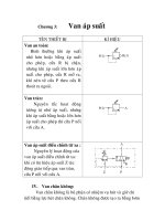
Oscillator
The internal oscillator frequency of FAN480X is
determined by the timing resistor and capacitor on RT/CT
pin. The frequency of the internal oscillator is given by:
1
0.56 360
OSC
TT T
f
R
CC
=
⋅⋅+
(6)
Because the PWM stage of FAN480X generally uses a
forward converter, it is required to limit the maximum duty
cycle at 50%. To have a small tolerance of the maximum
duty cycle, a frequency divider with toggle flip-flops is
used, as illustrated in Figure 8. The operation frequency of
PFC and PWM stage is one quarter (1/4) of the oscillator
frequency. (For FAN4800C and FAN4802/2L, the
operation frequencies for PFC and PWM stages are one
quarter (1/4) and one half (1/2) of the oscillator frequency,
respectively).
The dead time for the PFC gate drive signal is determined
by the equation:
360
DEAD T
tC
=
(7)
The dead time should be smaller than 2% of switching
period to minimize line current distortion around line zero
crossing.
RT/
CT
VREF
OSC
TQ
T-FF
T
Q
OPWM (FAN4800C, FAN4802/2L)
OPFC, OPWM
T-FF
Figure 8. Oscillator Configuration
AN-8027
© 2009 Fairchild Semiconductor Corporation www.fairchildsemi.com
Rev. 1.0.0 • 8/26/09 4
RT/
CT
OPFC
OPWM
OPWM (FAN4800C, FAN4802/2L)
PFC dead time
Figure 9. FAN480X Timing Diagram
PWM Stage
The PWM stage is capable of current-mode or voltage-
mode operation. In current-mode applications, the PWM
ramp (RAMP) is usually derived directly from a current
sensing resistor or current transformer in the primary of the
output stage and is thereby representative of the current
flowing in the converter’s output stage. I
LIMIT
, which
provides cycle-by-cycle current limiting, is typically
connected to RAMP in such applications.
For voltage-mode operation, RAMP can be connected to a
separate RC timing network to generate a voltage ramp
against which FBPWM voltage is compared. Under these
conditions, the use of voltage feed-forward from the PFC
bus can be used for better line transient response.
No voltage error amplifier is included in the PWM stage,
as this function is generally performed by a programmable
shunt regulator, such as KA431, in the secondary-side. To
facilitate the design of opto-coupler feedback circuitry, an
offset voltage is built into the inverting input of PWM
comparator that allows FBPWM to command a zero
percent duty cycle when its pin voltage is below 1.5V.
V
BOUT
RAMP
R
RAMP
C
RAMP
REF
+
-
PWM
FBPWM
1.5V
Figure 10. PWM Ramp Generation Circuit
PWM Current Limit
The ILIMIT pin is a direct input to the cycle-by-cycle
current limiter for the PWM section. If the input voltage at
this pin exceeds 1V, the output of the PWM is disabled
until the start of the next PWM clock cycle.
V
IN
OK Comparator
The V
IN
OK comparator monitors the output of the PFC
stage and inhibits the PWM stage if this voltage is less than
2.4V (96% of its nominal value). Once this voltage goes
above 2.4V, the PWM stage begins to soft-start.
PWM Soft-Start (SS)
PWM startup is controlled by the soft-start capacitor. A
10µA current source supplies the charging current for the
soft-start capacitor. Startup of the PWM is prohibited until
the soft-start capacitor voltage reaches 1.5V.
AN-8027
© 2009 Fairchild Semiconductor Corporation www.fairchildsemi.com
Rev. 1.0.0 • 8/26/09 5
Design Considerations
In this section, a design procedure is presented using the
schematic in Figure 11 as reference. A 300W PC power
supply application with universal input range is selected as
a design example. The design specifications are
summarized in 0. The two-switch forward converter is used
for DC/DC converter stage.
Design Specifications
Rated Voltage of Output 1 V
OUT1
= 5V PWM Stage Efficiency η
PWM
= 0.86
Rated Current of Output 1 I
OUT1
= 9A Hold-up Time t
HLD
= 20ms
Rated Voltage of Output 2 V
out2
= 12V Minimum PFC Output Voltage 310V
Rated Current of Output 2 I
OUT2
= 16.5A Nominal PFC output voltage V
O
_
PFC
= 387V
Rated Voltage of Output 3 V
OUT3
= -12V PFC Output Voltage Ripple 12V
PP
Rated Current of Output 3 I
OUT3
= 0.8A PFC Inductor Ripple Current dI = 40%
Rated Voltage of Output 4 V
OUT4
= 3.3V AC Input Voltage Frequency f
line
= 50 ~ 60Hz
Rated Current of Output 4 I
OUT4
= 13.5A Switching Frequency f
S
= 65KHz
Rated Output Power P
O
= 300W Total Harmonic Distortion α = 4%
Line Voltage Range 85~264V
AC
Magnetic Flux Density ΔB = 0.27T
Line Frequency 50Hz Current Density D
cma
= 400C-m/A
Brownout Protection Line Voltage 72V
AC
PWM Maximum Duty Cycle D
max
= 0.35
Overall Stage Efficiency η = 0.82 5V Output Current Ripple I
Lo1
= 44%
12V Output Current Ripple I
Lo2
= 10%
D
BOOST
L
BOOST
Q
1
C
BOOST
R
CS1
C
IF1
F
1
IEA
RAMP
RT/CT
FBPWM
SS
VRMS
ISENSE
IAC
ILIMIT
GND
OPWM
OPFC
VD
D
VREF
FBPFC
VEA
R
FB2
R
FB1
Q
2
Q
3
D
R1
L
1
1
L
2
1
C
O11
L
1
2
L
22
V
o1
V
o2
V
D
D
AC
Input
R
RAMP
FAN480X
Drv
R
IAC
Drv
Drv
C
O12
C
O21
C
O22
D
F1
D
F2
D
R2
V
BOUT
C
FB
C
REF
C
DD
C
LF2
R
LF2
R
CS2
D
R1
D
R2
R
RMS2
C
RMS1
C
RMS2
C
LF1
C
SS
C
T
C
RAMP
R
T
R
IC
C
IC1
C
IC2
D1
D2
R
RMS1
R
RMS3
R
B
C
VC2
C
VC1
R
VC
C
B
V
o1
V
o2
R
D
R
BIAS
R
OS1
R
OS2
R
OS3
R
F
C
F
R
LF1
V
o3
V
o4
Figure 11. Reference Circuit for Design Example
AN-8027
© 2009 Fairchild Semiconductor Corporation www.fairchildsemi.com
Rev. 1.0.0 • 8/26/09 6
[STEP-1] Define System Specifications
Since the overall system is comprised of two stages (PFC
and DC/DC), as shown in Figure 12, the input power and
output power of the boost stage are given as:
OUT
IN
P
P
η
=
(8)
OUT
BOUT
PWM
P
P
η
=
(9)
where
η is the overall efficiency and η
PWM
is the forward
converter efficiency.
The nominal output current of boost PFC stage is given as:
OUT
BOUT
PWM BOUT
P
I
V
η
=
(10)
Boost
PFC
Forward
DC/DC
P
IN
P
BOUT
V
BOUT
I
BOUT
P
OUT
V
OUT
Figure 12. Two Stage Configuration
(Design Example)
300
366
0.82
OUT
IN
P
P
W
η
===
300
349
0.86
OUT
BOUT
PWM
P
P
W
η
===
300
0.86 387
0.9
OUT
BOUT
PWM BOUT
P
I
A
V
η
⋅
===
[STEP-2] Frequency Setting
The switching frequency is determined by the timing resistor
and capacitor (R
T
and C
T
) as:
11
40.56
SW
TT
f
R
C
≅⋅
⋅⋅
(11)
It is typical to use a 470pF~1nF capacitor for 50~75kHz
switching frequency operation since the timing capacitor
value determines the maximum duty cycle of PFC gate drive
signal as:
.
.
11360
MIN
OFF
MAX PFC T SW
SW
T
D
Cf
T
=− =− ⋅ ⋅
(12)
(Design Example) Since the switching frequency is
65kHz, C
T
is selected as 1nF. Then the maximum duty
cycle of PFC gate drive signal is obtained as:
.
1 360 0.98
MAX PFC T SW
DCf
=
−⋅⋅=
The timing resistor is determined as:
11
6.9
40.56
T
SW T
R
k
fC
=
⋅=Ω
[STEP-3] Line Sensing Circuit Design
FAN480X senses the RMS value and instantaneous value of
line voltage using the VRMS and IAC pins, respectively, as
shown in Figure 13. The RMS value of the line voltage is
obtained by an averaging circuit using low pass filter with
two poles. Meanwhile, the instantaneous line voltage
information is obtained by sensing the current flowing into
IAC pin through R
IAC
.
IA
C
VRMS
R
RMS1
R
RMS2
R
RMS3
C
RMS1
C
RMS2
R
IAC
I
AC
V
IN
I
L
120/100Hz
f
p1
f
p2
RMS
IN
V
V
Figure 13. Line Sensing Circuits
RMS sensing circuit should be designed considering the
nominal operation range of line voltage and brownout
protection trip point as:
3
.
123
2
2
RMS
RMS UVL LINE BO
RMS RMS RMS
R
VV
RR R
π
−
=
⋅
++
(13)
3
.
123
2
RMS
RMS UVH LINE MIN
RMS RMS RMS
R
VV
RR R
−
<
++
(14)
where V
RMS-UVL
and V
RMS-UVH
are the brown OUT/IN
thresholds of V
RMS
.
It is typical to set R
RMS2
as 10% of R
RMS1
. The poles of the
low pass filter are given as:
1
12
1
2
P
RMS RMS
f
CR
π
≅
⋅⋅
(15)
2
23
1
2
P
RMS RMS
f
CR
π
≅
⋅⋅
(16)
AN-8027
© 2009 Fairchild Semiconductor Corporation www.fairchildsemi.com
Rev. 1.0.0 • 8/26/09 7
To properly attenuate the twice line frequency ripple in
V
RMS
, it is typical to set the poles around 10~20Hz.
The resistor R
IAC
should be large enough to prevent
saturation of the gain modulator as:
.
2
159
MAX
LINE BO
IAC
V
GA
R
μ
⋅<
(17)
where V
LINE.BO
is the brownout protection line voltage,
G
MAX
is the maximum modulator gain when V
RMS
is 1.08V
(which can be found in the datasheet), and 159µA is the
maximum output current of the gain modulator.
(Design Example) The brownout protection threshold is
1.05V (V
RMS-UVL
) and 1.9V (V
RMS-UVH
), respectively.
Then, the scaling down factor of the voltage divider is:
3
123 .
22
1.05
0.0162
72
22
RMS RMS UVL
RMS RMS RMS LINE BO
RV
RR R V
π
π
−
=⋅
++
=⋅ =
Then the startup of the PFC stage at the minimum line
voltage is checked as:
.3
123
2
85 2 0.0162 1.95 1.9
LINE MIN RMS
RMS RMS RMS
VR
V
RR R
⋅
=⋅ ⋅ = >
++
The resistors of the voltage divider network are selected
as R
RMS1
=2MΩ, R
RMS1
=200kΩ, and R
RMS1
=36kΩ.
To place the poles of the low pass filter at 15Hz and
22Hz, the capacitors are obtained as:
1
3
12
11
53
2 2 15 200 10
RMS
PRMS
CnF
fR
ππ
== =
⋅⋅ ⋅⋅ ×
2
3
23
11
200
2 2 22 36 10
RMS
PRMS
CnF
fR
ππ
≅= =
⋅⋅ ⋅⋅×
The condition for Resistor R
IAC
is:
.
66
2
2729
5.8
159 10 159 10
MAX
LINE BO
IAC
V
R
GM
−−
⋅⋅
>⋅==Ω
××
Therefore, 6M
Ω resistor is selected for R
IAC
.
[STEP-4] PFC Inductor Design
The duty cycle of boost switch at the peak of line voltage is
given as:
2
BOUT LINE
LP
BOUT
VV
D
V
−
=
(18)
Then, the maximum current ripple of the boost inductor at
the peak of line voltage for low line is given as:
.
22
1
LINE MIN BOUT LINE
L
BOOST BOUT SW
VV V
I
L
Vf
−
Δ= ⋅ ⋅
(19)
The average of boost inductor current over one switching
cycle at the peak of the line voltage for low line is given as:
.
.
2
OUT
LAVG
LINE MIN
P
I
V
η
=
⋅
(20)
Therefore, with a given current ripple factor
(K
RB
=ΔI
L
/I
LAVG
), the boost inductor value is obtained as:
2
.
2
1
LINE MIN BOUT LINE
BOOST
RB OUT BOUT SW
VVV
L
K
PV f
η
⋅−
=⋅ ⋅
⋅
(21)
The maximum current of boost inductor is given as:
.
.
2
(1 ) (1 )
22
PK
OUTRB RB
LLAVG
LINE MIN
P
KK
II
V
η
=⋅+= ⋅+
⋅
(22)
(Design Example) With the ripple current
specification (40%), the boost inductor is obtained as:
2
.
23
2
1
85 0.82 387 2 85 10
524
0.4 300 387 65
LINE MIN BOUT LINE
BOOST
RB OUT BOUT SW
VVV
L
KP V f
H
η
μ
−
⋅−
=⋅ ⋅
⋅
⋅−⋅
=⋅ ⋅=
⋅
The average of boost inductor current over one
switching cycle at the peak of the line voltage for low
line is obtained as:
.
.
2
2 300
6.09
85 0.82
OUT
LAVG
LINE MIN
P
I
A
V
η
⋅
===
⋅⋅
The maximum current of the boost inductor is given as:
.
2
(1 )
2
2 300 0.4
(1 ) 7.31
85 0.82 2
PK
OUT
RB
L
LINE MIN
PK
I
V
A
η
=⋅+
⋅
⋅
=⋅+=
⋅
[STEP-5] PFC Output Capacitor Selection
The output voltage ripple should be considered when
selecting the PFC output capacitor. Figure 14 shows the
twice line frequency ripple on the output voltage. With a
given specification of output ripple, the condition for the
output capacitor is obtained as:
,
2
BOUT
BOUT
LINE BOUT RIPPLE
I
C
fV
π
>
⋅⋅
(23)
where I
BOUT
is nominal output current of boost PFC stage
and V
BOUT,RIPPLE
is the peak-to-peak output voltage ripple
specification.
The hold-up time also should be considered when
determining the output capacitor as:
22
,
BOUT HOLD
BOUT
BOUT BOUT MIN
Pt
C
VV
⋅
>
−
(24)
where P
BOUT
is nominal output power of boost PFC stage,
t
HOLD
is the required holdup time, and V
BOUT,MIN
is the
allowable minimum PFC output voltage during hold-up time.
AN-8027
© 2009 Fairchild Semiconductor Corporation www.fairchildsemi.com
Rev. 1.0.0 • 8/26/09 8
,
(1 co s(4 ))
D AVG BOUT LINE
I
Ift
π
=−⋅⋅
BOUT
I
,
2
BOUT
BOUT RIPPLE
L
INE BOUT
I
V
fC
π
=
B
OUT
V
,DAVG
I
D
I
Figure 14. PFC Output Voltage Ripple
(Design Example) With the ripple specification of
12V
PP
, the capacitor should be:
,
0.9
239
225012
BOUT
BOUT
LINE BOUT RIPPLE
I
CF
fV
μ
ππ
>==
⋅⋅ ⋅⋅
Since minimum allowable output voltage during one
cycle line (20ms) drop-outs is 310V, the capacitor
should be:
3
2222
,
2 349 20 10
260
387 310
BOUT HOLD
BOUT
OUT OUT MIN
Pt
CF
VV
μ
−
⋅
⋅⋅×
>==
−−
Thus, 270
μF capacitor is selected for the PFC output
capacitor.
[STEP-6] PFC Output Sensing Circuit
To improve system efficiency at low line and light load
condition, FAN480X provides two-level PFC output
voltage. As shown in Figure 15, FAN480X monitors V
EA
and V
RMS
voltages to adjust the PFC output voltage.
The PFC output voltage when 20µA is enabled is given as:
2
2
20
(1 )
2.5
FB
BOUT BOUT
μAR
VV -
×
=×
(25)
It is typical second boost output voltage as 340V~300V
.
Figure 15. Two-Level PFC Output Block
The voltage divider network for the PFC output voltage
sensing should be designed such that FBPFC voltage is
2.5V at nominal PFC output voltage:
2
12
2.5
FB
BOUT
FB FB
R
VV
RR
×=
+
(26)
(Design Example) Assuming the second level of
PFC output voltage is 347V:
2
2
6
6
2.5
(1 )
20 10
347 2.5
(1 ) 12.9
387 20 10
BOUT
FB
BOUT
V
R
V
k
−
−
=− ⋅
×
=
−⋅ = Ω
×
13kΩ is selected for R
FB2
.
12
3
(1)
2.5
387
(1)13101999
2.5
BOUT
FB FB
V
RR
k
=−⋅
=
−⋅ × = Ω
2M
Ω is selected for R
FB1
.
[STEP-7] PFC Current-Sensing Circuit Design
Figure 16 shows the PFC compensation circuits. The first
step in compensation network design is to select the current-
sensing resistor of PFC converter considering the control
window of voltage loop. Since line feed-forward is used in
FAN480X, the output power is proportional to the voltage
control error amplifier voltage as:
0.6
()
0.6
MAX
EA
BOUT EA BOUT
SAT
EA
V
PV P
V
−
=⋅
−
(27)
where V
EA
SAT
is 5.6V and the maximum power limit of PFC
is:
2
.
1
MAX
MAX
LINE BO M
BOUT
IAC CS
VGR
P
RR
⋅
⋅
=
(28)
AN-8027
© 2009 Fairchild Semiconductor Corporation www.fairchildsemi.com
Rev. 1.0.0 • 8/26/09 9
It is typical to set the maximum power limit of PFC stage
around 1.2~1.5 of its nominal power such that the V
EA
is
around 4~4.5V at nominal output power. By adjusting the
current-sensing resistor for PFC stage, the maximum power
limit of PFC stage can be programmed.
To filter out the current ripple of switching frequency, an
RC filter is typically used for ISENSE pin. R
LF1
should not
be larger than 100Ω and the cut-off frequency of filter
should be 1/2~1/6 of the switching frequency.
Diodes D
1
and D
2
are required to prevent over-voltage on
ISENSE pin due to the inrush current that might damage
the IC. A fast recovery diode or ultra fast recovery diode is
recommended.
Figure 16. Gain Modulation Block
(Design Example) Setting the maximum power limit
of PFC stage as 450W, the current sensing resistor is
obtained as:
2
23
.
1
6
72 9 5.7 10
0.098
610 450
MAX
LINE BO M
CS
MAX
IAC BOUT
VGR
R
RP
⋅⋅
⋅⋅ ×
===Ω
×⋅
Thus, 0.1Ω resistor is selected.
[STEP-8] PFC Current Loop Design
The transfer function from duty cycle to the inductor
current of boost power stage is given as:
=
)
)
BOUT
L
B
OOST
Vi
sL
d
(29)
The transfer function from the output of the current control
error amplifier to the inductor current-sensing voltage is
obtained as:
11
⋅
=
⋅
)
)
CS CS BOUT
IEA RAMP BOOST
vRV
vVsL
(30)
where V
RAMP
is the peak to peak voltage of ramp signal for
current control PWM comparator, which is 2.55V.
The transfer function of the compensation circuit is given as:
1
1
22
1
2
IC
IEA II
CS
IP
s
fvf
s
vs
f
ππ
π
+
=⋅
+
)
)
(31)
where:
11
2
1
,
22
1
2
MI
II IZ
IC IC IC
IP
IC IC
G
f
fand
CRC
f
RC
ππ
π
==
⋅⋅⋅
=
⋅⋅
(32)
The procedure to design the feedback loop is as follows:
(a) Determine the crossover frequency (f
IC
) around
1/10~1/6 of the switching frequency. Then calculate
the gain of the transfer function of Equation (30) at
crossover frequency as:
11
@
2
IC
CS CS BOUT
IEA RAMP IC BOOST
ff
vRV
vVfL
π
=
⋅
=
⋅⋅
)
)
(33)
(b) Calculate R
IC
that makes the closed loop gain unity at
crossover frequency:
1
@
1
I
C
IC
CS
MI
IEA
ff
R
v
G
v
=
=
⋅
)
)
(34)
(c) Since the control-to-output transfer function of power
stage has -20dB/dec slope and -90
o
phase at the
crossover frequency is 0dB, as shown in Figure 17; it
is necessary to place the zero of the compensation
network (f
IZ
) around 1/3 of the crossover frequency so
that more than 45° phase margin is obtained. Then the
capacitor C
IC1
is determined as:
1
1
2/3
IC
IC C
C
Rf
π
=
⋅
(35)
(d) Place compensator high-frequency pole (f
CP
) at least a
decade higher than f
IC
to ensure that it does not
interfere with the phase margin of the current loop at
its crossover frequency.
2
1
2
IC
IP IC
C
fR
π
=
⋅⋅
(36)
AN-8027
© 2009 Fairchild Semiconductor Corporation www.fairchildsemi.com
Rev. 1.0.0 • 8/26/09 10
40dB
20dB
0dB
-20dB
-40dB
10Hz 100Hz 1kHz 10kHz 100kHz
f
IZ
Control-to-output
1MHz
f
IC
Compensation
Closed Loop Gain
60dB
f
IP
Figure 17. Current Loop Compensation
(Design Example) Setting the crossover frequency
as 7kHz:
11
@
36
2
0.1 387
0.66
2.55 2 7 10 524 10
IC
CS CS BOUT
IEA RAMP IC BOOST
ff
vRV
vVfL
π
π
=
−
⋅
=
⋅⋅
⋅
==
⋅⋅×⋅ ×
)
)
6
1
@
11
17
88 10 0.66
IC
IC
CS
MI
IEA
ff
R
k
v
G
v
−
=
===Ω
×⋅
⋅
)
)
1
33
11
4
2/3
17 10 2 7 10 / 3
IC
IC C
CnF
Rf
π
π
== =
⋅
×⋅⋅×
Setting the pole of the compensator at 70kHz,
2
33
11
0.13
2
270101710
IC
IP IC
CnF
fR
π
π
== =
⋅⋅
⋅× ⋅×
[STEP-9] PFC Voltage Loop Design
Since FAN480X employs line feed-forward, the power
stage transfer function becomes independent of the line
voltage. Then, the low-frequency, small-signal, control-to-
output transfer function is obtained as:
ˆ
1
ˆ
5
BOUT BOUT MAX
EA BOUT
vIK
vsC
⋅
≅⋅
(37)
where:
ˆ
1
ˆ
5
BOUT BOUT MAX
EA BOUT
vIK
vsC
⋅
≅⋅
(38)
Proportional and integration (PI) control with high-
frequency pole is typically used for compensation. The
compensation zero (f
VZ
) introduces phase boost, while the
high-frequency compensation pole (f
VP
) attenuates the
switching ripple, as shown in Figure 18.
Figure 18. Voltage Loop Compensation
The transfer function of the compensation network is
obtained as:
1
ˆ
22
ˆ
1
2
COMP VI VZ
OUT
VP
s
vff
s
vs
f
ππ
π
+
=⋅
+
(39)
where:
11
2
2.5 1
,
22
1
2
MV
VI VZ
BOUT VC VC VC
VP
VC VC
G
f
f and
VC RC
f
RC
ππ
π
=⋅ =
⋅⋅⋅
=
⋅⋅
(40)
The procedure to design the feedback loop is as follows:
(a)
Determine the crossover frequency (f
VC
) around
1/10~1/5 of the line frequency. Since the control-to-
output transfer function of power stage has -20dB/dec
slope and -90
o
phase at the crossover frequency, as
shown in Figure 18 as 0dB; it is necessary to place the
zero of the compensation network (f
VZ
) around the
crossover frequency so that 45° phase margin is
obtained. Then, the capacitor C
VC1
is determined as:
1
2
2.5
5(2)
MV BOUT MAX
VC
BOUT
BOUT VC
GI K
C
V
Cf
π
⋅⋅
=⋅
⋅⋅
(41)
To place the compensation zero at the crossover
frequency, the compensation resistor is obtained as:
1
1
2
VC
VC VC
R
fC
π
=
⋅⋅
(42)
(b)
Place compensator high-frequency pole (f
VP
) at least
a decade higher than f
C
to ensure that it does not
interfere with the phase margin of the voltage
regulation loop at its crossover frequency. It should
also be sufficiently lower than the switching
frequency of the converter so noise can be effectively
attenuated. Then, the capacitor C
VC2
is determined as:
2
1
2
VC
VP VC
C
fR
π
=
⋅⋅
(43)
AN-8027
© 2009 Fairchild Semiconductor Corporation www.fairchildsemi.com
Rev. 1.0.0 • 8/26/09 11
(Design Example) Setting the crossover frequency
as 22Hz:
1
2
6
6
2
2.5
5(2)
70 10 0.9 1.27 2.5
20
10
387
5 270 (2 22)
MV BOUT MAX
VC
BOUT
BOUT VC
GI K
C
V
Cf
nF
π
π
−
−
⋅⋅
=⋅
⋅⋅
×⋅⋅
=⋅=
×
⋅⋅⋅
9
1
11
362
2
2222010
VC
VC VC
R
k
fC
π
π
−
== =Ω
⋅⋅
⋅⋅×
Setting the pole of the compensator at 120Hz:
2
3
11
3.7
2
212036210
VC
VP VC
CnF
fR
π
π
== =
⋅⋅
⋅⋅×
[STEP-10] Transformer Design for PWM
Stage
Figure 19 shows the typical secondary-side circuit of
forward converter for multi-output of PC power application.
A common technique for winding multiple outputs with the
same polarity sharing a common ground is to stack the
secondary windings instead of winding each output
winding separately. This approach improves the load
regulation of the stacked outputs. The winding N
S1
in
Figure 19 must be sized to accommodate its output current,
plus the current of the output (+12V) stacked on top of it.
To get tight regulation of 3.3V output, magnetic amplifier
(MAG-AMP) is used. The saturable core of MAG-AMP
prevents the diode D
REC
from fully conducting by
introducing high impedance until it is saturated. This
allows the effective duty cycle of V
REC
to be controlled to
be regulated the output voltage.
MAG AMP
Control
MAG
AMP
N
p
+12V
+5V
+3.3
V
-12V
Additiona
l LC filter
Additiona
l LC filter
Additiona
l LC filter
Additiona
l LC filter
N
S
1
N
S
2
V
REC
+
-
D
REC
N
S
3
Figure 19. Typical Secondary-Side Circuit
Once the core for the transformer is determined, the
minimum number of turns for the transformer primary-side
to avoid saturation is given by:
MIN
MIN
BOUT MAX
P
eSW
VD
N
Af B
=
Δ
(44)
where
A
e
is the cross sectional area of the core in m
2
, f
SW
is
the switching frequency, and Δ
B is the maximum flux
density swing in Tesla for normal operation. Δ
B is typically
0.2-0.3 T for most power ferrite cores in the case of a
forward converter.
The turn ratio between the primary-side and secondary-side
winding for the first output is determined by:
111
()
MIN
BOUT MAXP
SOF
VDN
n
NVV
==
+
(45)
where V
F
is the diode forward-voltage drop.
Next, determine the proper integer for
N
S1
resulting in N
p
larger than
N
p
min
. Once the number of turns of the first
output is determined, the number of turns of other output
(n-th output) can be determined by:
() ()
() 1
11
On Fn
Sn S
OF
VV
N
N
VV
+
=⋅
+
(46)
The golden ratio between the secondary-side windings for
the best regulation of 3.3V, 5V, and 12V is known as
2:3:7.
(Design Example) The minimum PFC output voltage
is 310V and the maximum duty cycle of PWM
controller is 50%. By adding 5% margin to the
maximum duty cycle, D
MAX
=0.45 is used for
transformer design. Assuming ERL35 (Ae=107mm
2
)
core is used and ΔB=0.28, the minimum turns for the
transformer primary side is obtained as:
63
310 0.45
72
107 10 65 10 0.28
MIN
MIN
BOUT MAX
P
eSW
VD
N
Af B
−
⋅
== =
Δ
×⋅×⋅
The turns ratio for 5V output is obtained as:
310 0.45
25.6
( ) (5 0.45)
MIN
BOUT MAX
P
SOF
VD
N
n
NVV
⋅
== = =
++
The number of turns for the primary-side winding is
determined as:
1
2 25.6 51.2
MIN
pS P
NnN N=⋅ =× = <
11
3 25.6 76.8 3
MIN
pS P S
NnN N N
=
⋅=× = > ∴=
Then, the turns ratio for 12V output is obtained as:
22
21
11
12 0.7
36.997
50.45
OF
SS
OF
VV
NN
VV
+
+
=
⋅= ⋅= ≅
++
Therefore, the number of turns for each winding is
obtained as:
Np=78, N
S1
=3, N
S2
=7 (3+4 stack) and N
S3
=7.
AN-8027
© 2009 Fairchild Semiconductor Corporation www.fairchildsemi.com
Rev. 1.0.0 • 8/26/09 12
[STEP-11] Coupled Inductor Design for the
PWM Stage
When the forward converter has more than one output, as
shown in Figure 20, coupled inductors are usually employed
to improve the cross regulation and to reduce the ripple.
They are implemented by winding their separate coils on a
single, common core. The turns ratio should be the same as
the transformer turns ratio of the two outputs as:
22
11
SL
SL
N
N
N
N
=
(47)
N
p
N
S1
V
O1
L
1
N
S2
V
O2
L
2
N
L2
N
L1
Figure 20. Coupled Inductor
0
0
1POUT S
P
VN
N
⋅
2POUT S
P
VN
N
⋅
D1
D2
L1
L2
V
O1
V
O2
0
1POUT S
P
VN
N
⋅
D1
D2
N
L
LK
L
LK
V
O1
V
O2
N
Normalized
L
M
I
O1
I
O2
I
O2
I
O2
N
1
221
2
2
22
1
N
S
OOO
S
N
S
OO
S
N
VVV
N
N
II
N
==
=
I
SUM
Figure 21. Normalized Coupled Inductor Circuit
One way to understand the operation of coupled inductor is
to normalize the outputs to one output. Figure 21 shows
how to normalize the second output (V
O2
) to the first
output (V
O1
). The transformer and inductor turns are
divided by N
S2
/N
S1
, the voltage and current are adjusted by
N
S2
/N
S1
. It is assumed that the leakage inductances of the
coupled inductor are much smaller than the magnetizing
inductance and evenly distributed for each winding.
The inductor value of the first output can be obtained by:
11 1
1
12
()
(1 )
()
OO F
MIN
SUM
SW O O
SUM
VV V
LD
I
fPP
I
+
=⋅−
Δ
+
(48)
where:
12
1
MIN
BOUT
MIN MAX
BOUT
OO
SUM
O
V
DD
V
PP
I
V
=
+
=
(49)
Then, the ripple current for each output is given as:
1
11
1
2
OSUM
OO
II
I
I
ΔΔ
=⋅
(50)
21
222
1
2
OSUMS
OSO
IIN
I
NI
ΔΔ
=⋅⋅
(51)
(Design Example) The minimum duty cycle of
PWM stage at nominal input (PFC output) voltage is:
310
0.45 0.36
389
MIN
BOUT
MIN MAX
BOUT
V
DD
V
===
The sum of two normalize output current is:
12
1
243
48.6
5
OO
SUM
O
PP
I
A
V
+
===
Assuming 16% p-p ripple current in L
SUM
, the inductor
for the first output is obtained as:
11 1
1
12
3
()
(1 )
()
5(5 0.45)
(1 0.36) 6.9
65 10 (5 9 12 16.5) 0.16
OO F
MIN
SUM
SW O O
SUM
VV V
LD
I
fPP
I
uH
+
=⋅−
Δ
+
+
=⋅−=
××+×⋅
Then, the ripple current for each output is given as:
1
11
1 48.6 0.16 1
43%
229
OSUM
OO
II
II
ΔΔ
×
=⋅= ⋅=
21
222
1 48.6 0.16 3 1
10%
2 2 7 16.5
OSUMS
OSO
IIN
INI
ΔΔ
×
=⋅⋅= ⋅⋅=
AN-8027
© 2009 Fairchild Semiconductor Corporation www.fairchildsemi.com
Rev. 1.0.0 • 8/26/09 13
[STEP-12] PWM Ramp Circuit Design
For voltage-mode operation, the RAMP pin can be
connected to a DC voltage through a resistor. When it is
connected to the input of forward converter, ramp signal
slope is automatically adjusted according to the input
voltage providing line feed-forward operation. However, it
can cause more power dissipation in the resistor. For better
efficiency and lower standby power consumption, it is
recommended to connect the RAMP pin to the VREF pin.
Figure 22. Ramp Generation Circuit for PWM
It is typical to use 470pF~1nF capacitor on the RAMP pin
and to have the peak of the ramp signal around 2~3V.
The peak of the ram voltage is given as:
11
2
PK
REF
RAMP
RAMP RAMP SW
V
V
CR f
=⋅⋅
(52)
(Design Example) Selecting C
RAMP
and R
RAMP
as
1nF and 22k, the PWM ramp voltage is obtained as:
93 3
11
2
17.5 1
2.6
1 10 22 10 2 65 10
PK
REF
RAMP
RAMP RAMP SW
V
V
CR f
V
−
=⋅⋅
=⋅ ⋅ =
××⋅×
[STEP-13] Feedback Compensation Design
for PWM Stage
Figure 21 shows the typical cross regulation compensation
circuit configuration for multi-output converters. The small
signal characteristics of the compensation network is given as:
12
12
12
1/ 1/
()
1/
FBPWM
CZ CZ
B
OO
CP OS D F OS D F
v
ssR
vv
s R RCs R RCs
ωω
ω
++
=− ⋅ +
+
)
)
)
(53)
where:
12
1
2
2
1
(// )
1
1
()
CP
BBB
CZ
FF
CZ
F
OS F
RRC
RC
RRC
ω
ω
ω
=
=
=
+
(54)
FBPWM
VREF
R
B1
R
B
C
B
R
D
R
F
C
F
R
OS2
R
OS1
R
OS3
KA431
V
O2
V
O1
Figure 23. Feedback Compensation Circuit for
PWM Stage
The small signal equivalent circuit for control-to-output
transfer function of the PWM power stage can be simplified
as shown in Figure 24. The transfer function is fourth-order
system because additional LC filters are used to meet the
output voltage ripple specification. Therefore, it is
recommended to use engineering software, such as PSPICE
or Mathlab, to design the feedback loop.
L
LK
L
LK
V
O1
V
O2
N
C
O21
N
L
M
R
L1
R
L2
N
C
O11
L
L12
L
22
N
C
O22
N
C
O12
N
S1
:N
S2
V
O2
V
FBPWM
1
2
S
BOUT
S
N
V
N
⋅
V
RAMP
1
Figure 24. Simplified Small Signal Equivalent Circuit
for Control-to-Output Transfer Function
AN-8027
© 2009 Fairchild Semiconductor Corporation www.fairchildsemi.com
Rev. 1.0.0 • 8/26/09 14
Design Summary
Application Output Power Input Voltage Output Voltage / Output Current
ATX Power 300W 85~264V
AC
12V/16.5A;5V/9A;-12V/0.8A ;3.3V/13.5A
Features
Meets 80+ specification
FAN4800A fully pin-to-pin compatible with ML4800 and FAN4800 (needs few parts modify)
Switch-charge technique of gain modulator can provide better PF and lower THD
Leading and trailing modulation technique for reduce output ripple
Protections: OVP (Over-Voltage Protection), UVP (Under-Voltage Protection), OLP (Open-Loop Protection), and
maximum current limit
D
BOOST
L
BOOST
Q
1
C
BOOST
R
CS1
C
IF1
F
1
IEA
RAMP
RT/CT
FBPWM
SS
VRMS
ISENSE
IAC
ILIMIT
GND
OPWM
OPFC
VD
D
VREF
FBPFC
VEA
R
FB2
R
FB1
Q
2
Q
3
D
R1
L
1
1
L
2
1
C
O11
L
1
2
L
22
V
o1
V
o2
V
D
D
AC
Input
R
RAMP
FAN480X
R
IAC
C
O12
C
O21
C
O22
D
F1
D
F2
D
R2
V
BOUT
C
FB
C
REF
C
DD
C
LF2
R
LF2
R
CS2
D
R1
D
R2
R
RMS2
C
RMS1
C
RMS2
C
LF1
C
SS
C
T
C
RAMP
R
T
R
IC
C
IC1
C
IC2
D1
D2
R
RMS1
R
RMS3
R
B
C
VC2
C
VC1
R
VC
C
B
V
o1
V
o2
R
D
R
OS1
R
OS2
R
OS3
R
F
C
F
R
LF1
L
3
1
C
O31
V
o3
L
4
2
L
43
C
O21
C
O22
D
F2
L
4
1
V
o4
1.2 k
10
100
nF
32.4 k
12V
5V11 k
4.64 k
12V
5V
-12V
3.3V
1 k
300
10 k
1uF
3.4 k
5.45 k
FR157
FR157
FYPF2006DN
STPS60L45CW
SF34DG
220uF
2200uF
2200uF
1000uF
1000uF
1.8uH
2uH
FR157
FR157
FCP11N60
FCP11N60
10
10 k
10 k
100 nF
5
FDA18N50
BYC10600
270uF
0.1
1nF
6.9 k
2M
200 K
36 k
53nF
200n
F
6 M
2M
12.9k
17k 4nF
0.13nF
362k
20nF
3.7nF
1nF
22k
7.5k
0.47nF
Figure 25. Final Schematic of Design Example
AN-8027
© 2009 Fairchild Semiconductor Corporation www.fairchildsemi.com
Rev. 1.0.0 • 8/26/09 15
BOBBIN-ERL35
3mm 3mm
N
1
N
2
N
3
N
4
Margin TapeMargin Tape
N
5
Mylar Tape 3T
Mylar Tape 1T
Mylar Tape 1T
Mylar Tape 1T
Mylar Tape 3T
Figure 26. Forward Converter Transformer Structure
Winding Specification
No Pin(s-f) Wire Turns Winding Method
N
1
3-2 0.6Ф 37Ts Solenoid Winding
Insulation: Mylar Tape t = 0.03mm, 3 Layers
N2 8,9-10,11,12 Copper-Foil 10mil 3Ts Copper-Foil Width 18mm
Insulation: Mylar Tape t = 0.03mm, 1 Layers
N
3
13-8,9 1.0Ф*4 4Ts Solenoid Winding
Insulation: Mylar Tape t = 0.03mm, 1 Layers
N
4
10,11,12-14 0.4Ф 6Ts
Solenoid Winding
Insulation: Mylar Tape t = 0.03mm, 1 Layers
N
5
2-6,7 0.6Ф 37Ts Solenoid Winding
Insulation: Mylar Tape t = 0.03mm, 3 Layers
Core-ERL35
Insulation: Mylar Tape t = 0.03mm, 3 Layers
Insulation: Copper-Foil Tape t = 0.05mm-pin1 Open Loop
Insulation: Mylar Tape t = 0.03mm, 3 Layers
Core: ERL35 (Ae=107 mm
2
)
Bobbin: ERL35
Inductance: 13mH
AN-8027
© 2009 Fairchild Semiconductor Corporation www.fairchildsemi.com
Rev. 1.0.0 • 8/26/09 16
Appendix A
FAN480X Series Comparison Table of Relevant Parameters
FAN4800
New
Generation
FAN4800A
New
Generation
FAN4800C
New
Generation
FAN4801
New
Generation
FAN4802/2L
V
DD
Maximum Rating 20V 30V
V
DD
OVP 17.9V/Clamp 28/Auto-Recover
V
CC
UVLO 10V/13V 9.3/11V
Two-Level PFC
Output
NO NO YES
PFC Soft-Start NO YES
Brownout NO YES
PFC:PWM
Frequency
1:1 1:1 1:2 1:1 1:2
Frequency Range 68kHz~81kHz 50kHz~75kHz
Gate Clamp NO 16V
PFC Multiplier Traditional Switching Charge
V
IN
OK 2.25V/1.1V 2.40V/1.15V
PWM Maximum Duty 42%~49% 49.5%~50%
Startup Current 100μA 30μA
Soft-Start Current 20μA 10μA
PWM Comparator
Level Shift
1.0V 1.5V
R
AC
1~2MΩ 5~8 MΩ
MOSFET and Diode Reference Specification
PFC MOSFETs
Voltage Rating Part Number
500V
FQP13N50C, FQPF13N50C, FDP18N50, FDPF18N50, FDA18N50, FDP20N50(T),
FDPF20N50(T)
600V
FCP11N60, FCPF11N60, FCP16N60, FCPF16N60, FCP20N60S, FCPF20N60S, FCA20N60S,
FCP20N60, FCPF20N60
Boost Diodes
600V FFP08H60S, FFPF10H60S, FFP08S60S, FPF08S60SN, BYC10600
PWM MOSFETs
500V
FQP/PF9N50C, FQPF9N50C, FQP13N50C, FQPF13N50C, FQA13N50C, FDP18N50,
FDPF18N50, FDP20N50(T), FDPF20N50(T)
600V
FCP11N60, FCPF11N60, FCP16N60, FCPF16N60, FCA16N60, FCP20N60S, FCPF20N60S,
FCA20N60S, FCP20N60, FCPF20N60, FCA20N60
AN-8027
© 2009 Fairchild Semiconductor Corporation www.fairchildsemi.com
Rev. 1.0.0 • 8/26/09 17
References
FAN480X — PFC/Forward PWM Controller Combo (FAN4800, FAN4801, FAN4802)
AN-6078SC — FAN480X PFC+PWM Combo Controller Application
AN-6004 — 500W Power Factor Corrected (PFC) Design with FAN4810
AN-6032 — FAN4800 Combo Controller Applications
AN-42030 — Theory and Application of the ML4821 Average Current Mode PFC Controller
AN-42009 — ML4824 Combo Controller Applications
ATX 300W 80+ Evaluation Board of FAN4800A+SG6520+FSQ0170
DISCLAIMER
FAIRCHILD SEMICONDUCTOR RESERVES THE RIGHT TO MAKE CHANGES WITHOUT FURTHER NOTICE TO ANY PRODUCTS
HEREIN TO IMPROVE RELIABILITY, FUNCTION, OR DESIGN. FAIRCHILD DOES NOT ASSUME ANY LIABILITY ARISING OUT OF
THE APPLICATION OR USE OF ANY PRODUCT OR CIRCUIT DESCRIBED HEREIN; NEITHER DOES IT CONVEY ANY LICENSE
UNDER ITS PATENT RIGHTS, NOR THE RIGHTS OF OTHERS.
LIFE SUPPORT POLICY
FAIRCHILD’S PRODUCTS ARE NOT AUTHORIZED FOR USE AS CRITICAL COMPONENTS IN LIFE SUPPORT DEVICES OR
SYSTEMS WITHOUT THE EXPRESS WRITTEN APPROVAL OF THE PRESIDENT OF FAIRCHILD SEMICONDUCTOR
CORPORATION.
As used herein:
1. Life support devices or systems are devices or systems
which, (a) are intended for surgical implant into the body, or
(b) support or sustain life, or (c) whose failure to perform
when properly used in accordance with instructions for use
provided in the labeling, can be reasonably expected to
result in significant injury to the user.
2. A critical component is any component of a life support
device or system whose failure to perform can be
reasonably expected to cause the failure of the life support
device or system, or to affect its safety or effectiveness.