Essentials of Process Control phần 3 pdf
Bạn đang xem bản rút gọn của tài liệu. Xem và tải ngay bản đầy đủ của tài liệu tại đây (4.16 MB, 68 trang )
f
(VIAIWX
1.
Conventional Control Systems and Hardware
101
Conventional
FIGURE P3.8
II II
II
II
II
II II II
II
II
II II
II II
II
II
,,
I,
,lA
Tube-in-shell
II
Ii
Ii
II
condenser
II
II
,I
11
Dcphlegmator
since they eliminate a separate condenser shell, a reflux drum, and a reflux pump. Com-
ment on the relative controllability of the two process systems sketched above.
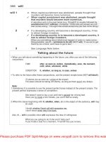
3.9. Compare quantitatively by digital simulation the dynamic performance of the three cool-
ers sketched on the next page with countercurrent flow, cocurrent flow, and circulating
water systems. Assume the tube and shell sides can each be represented by four perfectly
mixed lumps. Process design conditions are:
Flow rate =50,000 lb,,/hr
-
Inlet temperature = 250°F
Outlet temperature = 130°F
Heat capacity =OS
Btu/lb,,,
“F
Cooling-water design conditions are:
A. Countercurrent:
Inlet temperature = 80°F
Outlet temperature = 130°F
B. Cocurrent:
Inlet temperature = 80°F
Outlet temperature = 125°F
C. Circulating system:
Inlet temperature to cooler =
120°F
Outlet temperature from cooler =
125°F
Makeup water temperature to system = 80°F
Neglect the tube and shell metal. Tune PI controllers experimentally for each system.
Find the outlet temperature deviations for a 25 percent step increase in process flow
rate.
rm’r
ONI:.:
Time 1)omain l~ynaniics and
Control
Process
-
Water
Comment
II
I
rrocess
-Y-
vessel
Q-
Makeup
1
water
FIGURE P3.9
3.10. The overhead vapor from a depropanizer distillation column is totally condensed in
a water-cooled condenser at 120°F and 227 psig. The vapor is 95 mol% propane and
5 mol% isobutane. Its design flow rate is 25,500
lb,/hr,
and average latent heat of
vaporization is 125
Btu/lb,.
Cooling water inlet and outlet temperatures are 80°F and
lOS’F,
respectively. The
condenser heat transfer area is 1000
ft2.
The cooling water pressure drop through the
condenser at design rate is 5 psi. A linear-trim control valve is installed in the cooling
water line. The pressure drop over the valve is 30 psi at design with the valve half open.
The process pressure is measured by an electronic (4-20 mA) pressure transmit-
ter whose range is 100-300 psig. An analog electronic proportional controller with a
gain of 3 is used to control process pressure by manipulating cooling water How. The
FIGURE
P3.10
electronic signal from the controller (CO) is converted to a pneumatic signal in the
I/P
transducer.
(N) Calculate the cooling water flow rate (gprn) at design conditions.
(/I)
Calculate the size coefficient
(C,,)
of the control valve.
(c) Specify the action of the control valve and the controller.
(d)
What are the values of the signals PV, CO, SP, and
P,.;,,,,
at design conditions?
(e) Suppose the process pressure jurnps
IO
psi. How much will the cooling water Row
rate increase? Give values for PV, CO, and Pvi,lvc at this higher pressure. Assume
that the total pressure drop over the condenser and control valve is constant.
3.11. A circulating chilled-water system is used to cool an oil stream from 90 to 70°F in a
tube-in-shell heat exchanger. The ternperature of the chilled water entering the process
heat exchanger is maintained constant at 50°F by pumping the chilled water through a
refrigerated cooler located upstream of the process heat exchanger.
The design chilled-water rate for normal conditions is 1000 gpm, with chilled
water leaving the process heat exchanger at 60°F. Chilled-water pressure
drop
through
the process heat exchanger is 15 psi at 1000 gpm. Chilled-water pressure drop through
the refrigerated cooler is 15 psi at 1000 gpm. The heat transfer area of the process heat
exchanger is
I
143
ft*.
The temperature transmitter on the process oil stream leaving the heat exchanger
has a range of 50 to
150°F.
The range of the orifice differential-pressure flow transmitter
on the chilled water is 0 to 1500 gpm. All instrumentation is electronic (4 to 20 mA).
Assume the chilled-water pump is centrifugal with a flat pump curve.
(~1)
Design the chilled-water control valve so that it is 25 percent open at the 1000
gpm design rate and can pass a maximum flow of
1500
gpm. Assume linear trim
is used.
(b) Give values of the signals from the temperature transmitter, temperature controller,
and chilled-water flow transrnitter when the chilled-water flow is 1000 gpm.
(c) What is the pressure drop over the chilled-water valve when it is wide open?
(cl) What are the pressure drop and fraction open of the chilled-water control valve
when the chilled-water How rate is reduced to 500 gpm? What is the chilled-water
flow transmitter output at this rate’?
(e) If electric power costs 2.5 cents/kilowatt-hour, what are the annual pumping costs
for the chilled-water pump at the design 1000 gpm
rate’!
What horsepower motor
is required to drive the chilled-water pump? (I hp = 550 ft-lbtkec = 746 W.)
104
l’:\lU
ONI!. Time
f>(~rllain
L)ynilrnics
irrtd
C’0111roi
Elcvalion
20’
TanA
aI
;~lmosplwic
Elevation IS’
Circulating
cliillccl
watei
__
1
Refrigerant
I
Elevation 0’
c
FIGURE P3.11
90°F
I
Hot oil
Cooled oil
I
70°F
3.12. Tray 4 temperature on the Lehigh distillation column is controlled by a pneumatic PI
controller with a 2-minute reset time and a 50 percent proportional band. Tempera-
ture controller output
(COT)
adjusts the setpoint of a steam flow controller (reset time
0.1 minutes and proportional band 100 percent). Column base level is controlled by a
pneumatic proportional-only controller that sets the bottoms product withdrawal rate.
Transmitter ranges are:
Tray 4 temperature
Steam flow
Bottoms flow
Base level
60-l 20°C
O-4.2
lb,/min
(orificelAP transmitter)
O-l gpm (orificelAP transmitter)
O-20 in
Hz0
PVL
c
Bottoms
1
'OF
&-,
pvF
75 psig
steam
SP
FIGURE P3.12
(~ll~iw:~~
3
C’onvcntional
Control Systems and tlardwarc
I
OS
Srcxly-slate
operating
conditions arc:
Tray
4
tcnipcrati~rc
13asc
lcvcl
Stcnlll
flow
Ho~tolns
flow
83°C
55% full
3.5
Ib,,,/niin
0.6 gpm
Prcssurc drop over the control valve on the bottoms product is constant at 30 psi.
This control valve has linear trim and a
C,,
of 0.5. The formula for steam
flow
through
a control valve (when the upstream pressure
P,Y
in psia is greater than twice the down-
stlxam pressure) is
where W = steam flow rate
(Ib,,,/hr)
c,,
= 4
X = valve fraction open (linear trim)
(a) Calculate the control signals from the base level transmitter, temperature transmit-
ter, steam flow transmitter, bottoms flow transmitter, temperature controller, steam
flow controller, and base level controller.
(b) What is the instantaneous effect of a +S’C step change in tray 4 temperature on
the control signals and flow rates?
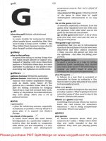
3.13. A reactor is cooled by a circulating jacket water system. The system employs a double
cascade reactor temperature control to jacket temperature control to makeup cooling
water flow control. Instrumentation details are as follows (electronic, 4-20 mA):
Reactor temperature transmitter range: 50-250°F
Circulating jacket water temperature transmitter range: 50-l 50°F
Makeup cooling water flow transmitter range: O-250 gpm
(orifice plate + differential pressure transmitter)
Control valve: linear trim, constant
35-psi
pressure drop
Normal operating conditions are:
Reactor temperature =
140°F
Circulating water temperature = 106”
Makeup water flow rate = 63 gpm
Control valve 25% open
(u) Specify the action and size of the makeup cooling water control valve.
(b) Calculate the milliampere control signals from all transmitters and controllers at
normal operating conditions.
(c)
Specify whether each controller is reverse or direct-acting.
(d) Calculate the instantaneous values of all control signals if reactor temperature in-
creases suddenly by 10°F.
Proportional band settings of the reactor temperature controller, circulating jacket water
temperature controller, and cooling water flow controller are 20, 67, and 200, respec-
tively.
Reactor
::; I-
f
Cooling
jacket
Pump
Makeup
cooling
water
FIGURE P3.13
3.14. Three vertical cylindrical tanks ( IO feet high, 10 feet in diameter) are used in a process.
Two tanks are process tanks and are level-controlled by manipulating outflows using
proportional-only level controllers (PB = 100). Level transmitter spans are 10 feet.
Control valves are linear, 50 percent open at the normal liquid rate of 1000 gpm, and
air-to-open, with constant pressure drop. These two process tanks are 50 percent full at
the normal liquid rate of 1000 gpm.
I
Process
I
Process
vessel 2
i
Surge
tank
(‘IIWI
I
I<
1
(‘onvcntional Control Systems
antf
Hardware
IO7
‘l‘hc third tallk is
;I
surge tank wl~osc lcvcl is uncontrolled. Liquid
is
pumped
from
this tank to the
lirst
process vessel, on to the second tank in series, and then back to the
surge tank. If the surge tank is half full when
1000
gpm
of liquid are circulated, how
full will the surge tank be, at the new steady state, when the circulating rate around the
system is cut to 500 gpm?
3.15. Liquid (sp gr = I ) is pumped from a tank at atmospheric pressure through a heat
exchanger and a control valve into a process
vessel
held at
100
psig pressure. The
system is designed for a maximum flow rate of 400 gpm. At this maximum flow rate
the pressure drop across the heat exchanger is SO psi.
A centrifugal pump is used with a performance curve that
can
be approximated
by the relationship
AP,, = 198.33
-
1.458 x
10P”F2
where AP,, = pump head in psi
F =
fIow
rate in gpm
The control valve has linear trim.
(cl)
Calculate the fraction that the control valve is open when the throughput is reduced
to 200 gpm by pinching down on the control valve.
(0) An orifice-plate differential-pressure transmitter is used for flow measurement. If
the maximum full-scale flow reading is 400 gpm, what will the output signal from
the electronic flow transmitter be when the flow rate is reduced to I50 gpm?
3.16. Design liquid level control systems for the base of a distillation column and for the
vaporizer shown. Steam flow to the vaporizer is held constant and cannot be used to
control level. Liquid feed to the vaporizer can come from the column and/or from the
surge tank. Liquid from the column can go to the vaporizer and/or to the surge tank.
Liquid
feed
FIGURE P3.16
Vapor
108
PARTONE: Time Domain Dynamics and Control
Since
the liquid
must
be
cooled
if it is ~ellt to the SllrgC tank and then rcheatcd in
the vaporizer, there is an energy COSt penalty
aSWciated
with SClldillg
111WC
INaterial
(0
the surge tank than is absolutely necessary.
Your level control system should therefore
hold both levels and also minimize the amount of material sent to the surge tank. (If;rlt:
One way to accomplish this is to make sure that the valves in the lines to and from the
surge tank cannot be open simultaneously.)
3.17. A chemical reactor is cooled by a circulating oil system as shown. Oil is circulatctl
through a water-cooled heat exchanger and through control valve
VI.
A portion of the
oil stream can be bypassed around the heat exchanger through control valve
VI.
The
system is to be designed so that at design conditions:
l The oil flow rate through the heat exchanger is 50 gpm (sp gr = I) with a IO-psi
pressure drop across the heat exchanger and with the
VI
control valve
25
percent
open.
l The oil flow rate through the bypass is
100
gpm with the
VI
control valve SO
percent open.
Both control valves have linear trim. The circulating pump has a fat pump curve. A
maximum oil flow rate through the heat exchanger of 100 gpm is required.
(a) Specify the action of the two control valves and the two temperature controllers.
(b) Calculate the size (C,) of the two control valves and the design pressure drops over
the two valves.
(c) How much oil will circulate through the bypass valve if it is wide open and the
valve in the heat exchanger loop is shut?
Y2
Circulating oil
FIGURE P3.17
3.18. The formula for the flow of saturated steam through a control valve is
w
=
2.
K,.f&)
J(P,
4
f-q(P,
-
P2)
where W =
Ib,/hr
steam
PI
= upstream pressure, psia
P2
= downstream pressure, psia
FIGURE P3.18
The temperature of the steam-cooled reactor shown is 285°F. The heat that must
be transferred from the reactor into the steam generation system is 2.5 X
IO”
Btu/hr. The
overall heat transfer coefficient for the cooling coils is 300 Btu/hr
ft’
“F. The steam dis-
charges into a
25psia
steam header. The enthalpy difference between saturated steam
and liquid condensate is 1000
Btu/lb,,,.
The vapor pressure of water can be approxi-
mated over this range of pressure by a straight line.
T(“F)
= 195 +
f.8P(psia)
Design two systems, one where the steam drum pressure is 40 psia at design and another
where it is 30 psia.
(a) Calculate the area of the cooling coils for each case.
(b) Calculate the
C,,
value for the steam valve in each case, assuming that the valve is
half open at design conditions: fix, = 0.5.
(c) What is the maximum heat removal capacity of the system for each case‘?
3.19. Cooling water is pumped through the jacket of a reactor. The pump and the control
valve must be designed so that:
(a) The normal cooling water flow rate is 250 gpm.
(b) The maximum emergency rate is 500 gpm.
(c) The valve cannot be less than
IO
percent open when the flow rate is 100 gpm.
Pressure drop through the jacket is IO psi at design. The pump curve has a linear slope
of -0. I psi/gpm.
Calculate the
C,,
value of the control valve, the pump head at design rate, the size
of the motor required to drive the pump, the fraction that the valve is open at design,
and the pressure drop over the valve at design rate.
3.20. A
CZ
splitter column uses vapor recompression. Because of the low temperature re-
quired to stay below the critical temperatures of ethylene and ethane, the auxiliary
condenser must be cooled by a propane refrigeration system.
(u) Specify the action of all control valves.
(b) Sketch a control concept diagram that accomplishes the following objectives:
Level in the propane vaporizer is controlled by the liquid propane flow from the
refrigeration surge drum.
110
PARTONE:
Time Domain Dynamics and
COII~~()~
Cohnn
compressor
d
q&-
H.P.
stcanl
-
Flash valve
-
Propane
surge
vaporizer
drum
Auxiliary
condenser
Distillate
FIGURE P3.20
Column pressure is controlled by adjusting the speed of the column compressor
through a steam flow control-speed control-pressure control cascade system.
Reflux is flow controlled. Reflux drum level sets distillate flow. Base level sets
bottoms flow.
Column tray 10 temperature is controlled by adjusting the pressure in the propane
vaporizer, which is controlled by refrigeration compressor speed.
High column pressure opens the valve to the flare.
(c) How effective do you think the column temperature control will be? Suggest an
improved control system that still achieves minimum energy consumption in the
two compressors.
3.21. Hot oil from the base of a distillation column is used to reboil two other distillation
columns that operate at lower temperatures. The design flow rates through reboilers
1
and 2 are 100 gpm and 150 gpm, respectively. At these flow rates, the pressure drops
through the reboilers are 20 psi and 30 psi. The hot oil pump has a flat pump curve.
Size the two control valves and the pump so that:
l Maximum flow rates through each reboiler can be at least twice design.
l At minimum turndown rates, where only half the design flow rates are required,
the control valves are no less than
10
percent open.
-
I lot
oil
Reboiler
2
FIGURE P3.21
3.22. A reactor is cooled by circulating liquid through a heat exchanger that produces low-
pressure (10 psig) steam. This steam is then split between a compressor and a turbine.
The portion that goes through the turbine drives the compressor. The portion that goes
through the compressor is used by 50-psig steam users. The turbine can also use
IOO-
psig steam to provide power required beyond that available in the IO-psig steam. (See
the figure on the next page.)
Sketch a control concept diagram that includes all valve actions and the following
control strategies:
l Reactor temperature is controlled by changing the setpoint of the turbine speed
controller.
l Turbine speed is controlled by two split-range valves, one on the IO-psig inlet
to the turbine and the other on the
lOO-psig
inlet. Your instrumentation system
should be designed so that the valve on the lo-psig steam is wide open before
any
lOO-psig
steam is used.
l Liquid circulation from the reactor to the heat exchanger is flow controlled.
l Condensate level in the condensate drum is controlled by manipulating BFW
(boiler feed water).
l Condensate makeup to the steam drum is ratioed to the lo-psig steam flow rate
from the steam drum. This ratio is then reset by the steam drum level controller.
l Pressure in the 50-psig steam header is controlled by adding
lOO-psig
steam.
l A high-pressure controller opens the vent valve on the lo-psig header when the
pressure in the IO-psig header is too high.
l Compressor surge is prevented by using a low-flow controller that opens the
valve in the spillback line from compressor discharge to compressor suction.
3.23. Water is pumped from an atmosphere tank, through a heat exchanger and a control
,IQI\,P ;nt,\
‘,
nrP~cllr-;-,~A
\IOCCPI
The
r\n~ratin<r
nr~cc,,rp
in
the
vr~~cr~l
c.:,,,
v:,t-v
l’r,,,n
I
12
IVIKI‘ONI:-
Time
h~lllnitl
I~ynaniics
~tncl
Conrr-01
IO
psig stcml
.
50
psig
steam
to
users
Heat
exchanger
Spill back
i-:
STEAM
COMPRESSOR
Contlcnsntc
makeup
FIGURE P3.22
200 to 300
PSI@
‘0
but is 250 psig at design. Design flow rate is 100 gpm with a 20-psi
pressure drop through the heat exchanger. Maximum flow rate is 250 gpm. Minimum
flow rate is 25 gpm. A centrifugal pump is used that has a straight-line pump curve
with a slope of -0.1 psi/gpm.
Design the control valve and pump so that the maximum and minimum flow rates
can be handled with the valve never less than 10 percent open.
3.24. Reactant liquid is pumped into a batch reactor at a variable rate. The reactor pressure
also varies during the batch cycle. Specify the control valve size and the centrifugal
pump head required. Assume a flat pump curve.
The initial flow rate into the reactor is 20 gpm (sp gr = 1). It is decreased linearly
with time down to 5 gpm at 5 hours into the batch cycle. The initial reactor pressure is
50 psig. It increases linearly with time up to 350 psig at 5 hours. The reactant liquid
comes from a tank at atmospheric pressure.
3.25. Water is pumped from an atmospheric tank into a vessel at 50 psig through a heat
exchanger. There is a bypass around the heat exchanger. The pump has a flat curve.
The heat exchanger pressure drop is 30 psi with 200 gpm of flow through it.
FIGURE P3.25
Size the pump and the two control valves so that:
l 200 gpm can be bypassed.
l Flow through the heat exchanger can be varied from 75 gpm to 300 gpm.
3.26. An engineer from Catastrophic Chemical Company has designed a system in which
a positive-displacement pump is used to pump water from an atmospheric tank into a
pressurized tank operating at 150 psig. A control valve is installed between the pump
discharge and the pressurized tank.
With the pump running at a constant speed and stroke length, 350 gpm of water is
pumped when the control valve is wide open and the pump discharge pressure is 200
psig.
If the control valve is pinched back to 50 percent open, what will be the flow rate
of water and the pump discharge pressure?
3.27. Hot oil from a tank at 400°F is pumped through a heat exchanger to vaporize a liquid.
boiling at 200°F. A control valve is used to set the flow rate of oil through the loop.
Assume the pump has a flat pump curve. The pressure drop over the control valve is
_
30 psi and the pressure drop over the heat exchanger is 35 psi under the normal design
conditions given below:
Heat transferred in heat exchanger =
17
X
IO6
Btu/hr
Hot oil inlet temperature = 400°F
Hot oil exit temperature = 350°F
Fraction valve open = 0.8
200°F
FIGURE P3.27
The
hot oil gives off sensible heat only (hear capacity
-=
0.5
13tu/lb,,,
“F. density =
4.58
Ih,,,/gal).
‘The heat transfer
area
in the cxhangcr is 652
ft’,
Assume the temperature
on
the
tube
side of the heat exchanger stays constant at 200°F and the inlet hot oil
temperature stays constant at 400°F. A log mean temperature difference must be used.
Assuming the heat transfer coefficient dots not change with the
tlow
rate, what
will the valve opening be when the heat transfer rate in the heat exchanger is half the
normal design value?
3.28. A control valve-pump system proposed by Connell (Cller~i~rl
Etlgiuec~r-i/lg.
September
28, 1987, p. 123) consists of a centrifugal pump, several heat exchangers, a furnace, an
orifice, and a control valve. Liquid is pumped through this circuit and up into a column
that operates at 20 psig. Because the line running up the column is full of liquid, there
is a hydraulic pressure differential between the base of the column and the point of
entry into the column of
15
psi.
The pump suction pressure is constant at IO psig. The design flow rate is 500 gpm.
At this flow rate the pressure drop over the flow orifice is 2 psi, through the piping is
30 psi, over three heat exchangers is 32 psi, and over the furnace is 60 psi. Assume a
flat pump curve and a specific gravity of 1.
Connell recommends that a control valve be used that takes a 76-psi pressure drop
at design flow rate. The system should be able to increase flow to I20 percent of design.
(a) Calculate the pressure drop over the valve at the maximum flow rate.
(b) Calculate the pump discharge pressure and the control valve C,.
(c) Calculate the fraction that the valve is open at design.
(d) If turndown is limited to a valve opening of 10 percent, what is the minimum flow
rate?
3.29. A circulating-water cooling system is used to cool a chemical reactor. Treated water is
pumped through a heat exchanger and then through the cooling coils inside the reactor.
Some of the circulating water is bypassed around the heat exchanger. Cooling tower
water is used on the shell side of the heat exchanger to cool the circulating water.
Two linear-trim control valves are used. Valve 1 in the bypass line is AO, and
_
valve 2 in the heat exchanger line is AC. Both valves get their inputs from the CO
signal from a temperature controller.
Design conditions are: CO is 75 percent of scale, flow through valve 1 is 300 gpm,
flow through valve 2 is 100 gpm, pressure drop through the coil is 20 psi, and pressure
drop through the heat exchanger is 5 psi. The centrifugal pump has a flat pump curve.
If the maximum flow rate through the heat exchanger is 300 gpm when the CO
signal is 0 percent of scale, calculate the C, value of both control valves and the required
pump head. What is the flow rate through valve 1 when the CO signal is 100 percent
of scale?
3.30. A gravity-flow condenser uses the hydraulic head of the liquid in the line from the con-
denser to overcome the pressure drop over the control valve and the difference between
the pressure at the top of the distillation column
PI
and the pressure at the bottom of the
condenser
Pz.
The pressure difference is due to the flow of vapor through the vapor line
and condenser. When the flow rate of vapor from the top of the column is 14 1.6
Ib,,/min,
the pressure drop
PI
-
PI is 2 psi. The pressure drop due to the liquid flowing through
the liquid return line is negligible. Liquid density is 62.4 lb,,/ft’.
(a) If we want the height of liquid in the return line to be 5 ft at design conditions
(141.6
lb,/min
of liquid with the control valve half open), what is the required
control valve C,.‘?
(‘ilAlw:l~
3:
Conventional Control Systems and
I
InrdwilK
11s
(/I)
If the vapor and liquid
how
ra!cs
both increase to 208.2
Ib,,,/min
when the control
valve is wide
O~XI~,
what is
the
height of liquid in the liquid return line?
3.31. A hot vapor bypass pressure control system is used on a distillation column. Some
of
the vapor from the top of the column passes through a control valve and is added to
the vapor space in the top of the reflux drum. The column operates at 7 atm and the
ovcrhcad vapor is essentially pure isobutane. The vapor pressure of isobutane is given
by the following equation:
In P = 9.91552
-
2586.8/(T + 273)
where
P
is in atmospheres and T is in degrees Celsius.
Since the
flow
through the valve is isenthalpic, the temperature in the hot vapor
space in the reflux drum is the same as the temperature in the top of the column (as-
suming isobutane is an ideal gas at this pressure).
Most of the vapor from the top of the column is condensed and subcooled in a
condenser. This subcooled liquid then flows into the base of the reflux drum. There is
heat transfer between the hot vapor and the cooler vapor-liquid interface (at tempera-
ture 7J and between the vapor-liquid interface and the cooler-subcooled reflux in the
tank (at temperature
TK).
The vapor film coefficient is 10 Btu/hr
“C
ft*,
and the liquid
film coefficient is 30 Btu/hr
“C
ft*.
The heat transfer area on the surface of the liquid
is 72
ft*.
The heat of vaporization of isobutane is 120
Btu/lb,.
The control valve is sized to be IO percent open during summer operation, when
the temperature of the subcooled liquid in the tank is 45°C. Use the control valve sizing
formula
where F = Ib/hr of vapor flow
P
Cd
= pressure in the column = 7 atm
P = pressure in the reflux drum = saturation pressure of isobutane at the
temperature T of the interface between the liquid and vapor phases.
(a) Calculate the
6,
value of the control valve.
(b) Calculate the fraction that the valve will be open during winter operation, when
the temperature of the subcooled reflux is 15°C. Column pressure is constant at
7 atm.
3.32.
The steam supply to a sterilizer comes from an 84.7-psia header and is saturated vapor
with an enthalpy of 1184.1 Btu/lb. It flows through a control valve into the sterilizer,
where a temperature of 250°F is desired (saturation pressure of 29.82 psia and saturated
liquid enthalpy of 218.48 Btu/lb). Condensate leaves through a steam trap. The heat
required to maintain the sterilizer at its desired temperature is 200,000 Btu/hr. The
control valve should be 25 percent open at these steady-state conditions. A pressure
controller is used to control pressure in the sterilizer. The pressure transmitter has a
range of O-75 psig. Ail instrumentation is electronic with a signal range of 4 to 20 mA.
The equation for steam flow through a control valve when the upstream pressure
is more than twice the downstream pressure is
where
Fs
= steam flow rate, Ib/hr
/Is
= upstream pressure, psia
((I)
Slloultl
tllc
steam
control
valve
bc
A0
or AC?
(h) Calciilate
lhc
C,,
value
of
the
control valve.
(c*)
Calculate the PV signal from the pressure transmitter
and
the CO signal from the
pressure controller under steady-state conditions.
((1)
If the proportional band of the controller is 75 and the pressure in the sterilizer
suddenly drops by 5 psi, calculate the instantaneous value of the controller output
and the new value of the steam flow rate.
3.33. Design a centrifugal pump and control valve system so that a maximum flow rate
ot
75 gpm and a minimum flow rate of 25 gpm are achievable with the control
valve
at
100
percent and IO percent open, respectively. Liquid is pumped from a tank whose
pressure can vary from 50 to 75 psia. The material is pumped through a heat exchange1
(which takes 30-psi pressure drop at 50 gpm) and a control valve into a tank whose
pressure can vary from 250 to 300 psia. Assume a flat pump curve.
___
-
Advanced Control Systems.
In
the previous chapter we discussed the elements of a conventional single-input,
single-output (SISO) feedback control loop. This configuration forms the backbone
of almost all process control structures.
However, over the years a number of slightly more complex structures have
been developed that can, in some cases, significantly improve the performance of a
control system. These structures include ratio control, cascade control, and override
control.
4.1
RATIO CONTROL
As the name implies, ratio control involves keeping constant the ratio of two or more
flow rates. The flow rate of the “wild” or uncontrolled stream is measured, and the
flow rate of the manipulated stream is changed to keep the two streams at a constant
ratio with each other. Common examples include holding a constant reflux ratio on a
distillation column, keeping stoichiometric amounts of two reactants being fed into a
reactor, and purging off a fixed percentage of the feed stream to a unit. Ratio control
is often part of afeedforward control structure, which we will discuss in Section 4.7.
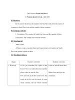
Ratio control is achieved by two alternative schemes, shown in Fig. 4.1. In the
scheme shown in Fig. 4. la, the two flow rates are measured and their ratio is com-
puted (by the divider). This computed ratio signal is fed into a conventional PI con-
troller as the process variable (PV) signal. The setpoint of the ratio controller is the
desired ratio. The output of the controller goes to the valve on the manipulated vari-
able stream, which changes its flow rate in the correct direction to hold the ratio of
the two flows constant. This computed ratio signal can also be used to trigger an
alarm or an interlock.
In the scheme shown in Fig. 4. lh, the wild flow is measured and this flow signal
is multiplied by a constant, which is the desired ratio. The output of the multiplier is
the setpoint of a remote-set
how
controller on the manipulated variable.
117
I
I
I
I
Manipulated stream
(fl)
Wild stream
M”“ipt-$
Constant
I
I
II
Manipulated stream
(b)
FIGURE 4.1
Ratio control. (n) Ratio compute.
(b) Flow set.
If orifice plates are used as flow sensors, the signals from the differential-pres-
sure transmitters are really the squares of the flow rates, Some instrument engineers
prefer to put in square-root extractors and convert everything to linear flow signals.
4.2
CASCADE CONTROL
One of the most useful concepts in advanced control is cascade control. A cascade
control structure has two feedback controllers, with the output of the primary (or
master) controIlcr changing the sctpoint of the secondary (or slave) controller. The
output of the secondary goes to the valve,
as
shown in Fig. 4.2.
There arc two purposes for cascade control: (
I
) to eliminate the effects of some
disturbances, and (2) to improve the dynamic performance of the control loop.
To illustrate the disturbance re.jection effect, consider the distillation column re-
boiler shown in Fig.
4.2~1.
Suppose the steam supply pressure increases. The pressure
drop over the control valve will bc larger,
so
the steam flow rate will increase. With
Conventional single loop
Cascade control loop
Primary
controller
Steam
l&boiler
Distillation
column
\
Reboiler
I
Primary
Circulation
pump
I
Cooling
water
makeup
TT
=
temperature transmitter
TC
=
temperature controller
LC
=
level controller
(h)
FIGURE 4.2
Conventional versus cascade control.
((1)
Distillation*column-reboiler temperature
120
PAKTONR:
Time Domain Dynamics and
Contt-ol
the single-loop tcmpcrafure controller, no correction will be made until the higher
steam flow rate increases the vapor
boilup
and the higher vapor rate begins to raise
the temperature on tray 5. Thus, the whole system is disturbed by a supply steam
pressure change.
With the cascade control system, the steam flow controller will immediately see
the increase in steam flow and will pinch back on the steam valve to return the steam
flow rate to its setpoint. Thus, the reboiler and
the
column are only slightly affected
by the steam supply pressure disturbance.
Figure
4.2~3
shows another common system where cascade control is used. The
reactor temperature controller is the primary controller; the jacket temperature con-
troller is the secondary controller. The reactor temperature control is isolated by the
cascade system from disturbances in cooling-water inlet temperature and supply
pressure.
This system is also a good illustration of the improvement in dynamic perfor-
mance that cascade control can provide in some systems. As we show quantitatively
in Chapter 9, the closedloop time constant of the reactor temperature will be smaller
when the cascade system is used than when the reactor temperature sets the cooling
water makeup valve directly. Therefore, performance is improved by using cascade
control.
We also talk in Chapter 9 about the two types of cascade control: series cascade
and parallel cascade. The two examples just discussed are both series cascade sys-
tems because the manipulated variable affects the secondary controlled variable, and
then the secondary variable affectsthe primary variable. In a parallel cascade system
the manipulated variable affects both the primary and the secondary controlled vari-
ables directly. Thus, the two processes are basically different and result in different
dynamic characteristics. We quantify these ideas later.
4.3
COklPUTED VARIABLE CONTROL
One of the most logical and earliest extensions of conventional control was the idea
of controlling the variable that was of
rea’l
interest by computing its value from other
measurements.
For example, suppose we want to control the mass flow rate of a gas. Controlling
the pressure drop over the orifice plate gives only an approximate mass flow rate
because gas density varies with temperature and pressure in the line. By measur-
ing temperature, pressure, and orifice plate pressure drop and feeding these signals
into a mass-flow-rate computer, the mass flow rate can be controlled as sketched in
Fig.
4.3a.
Another example is shown in Fig.
4.3b,
where a hot oil stream is used to reboil a
distillation column. Controlling the flow rate of the hot oil does not guarantee a fixed
heat input because the inlet oil temperature can vary and the
1T
requirements in the
reboiler can change. The heat input
Q
can be computed from the flow rate and the
inlet and outlet temperatures, and this
Q
can then be controlled.
As a final example, consider the problem of controlling the temperature in a dis-
tillation column where significant pressure changes occur. We really want to measure
-
t
6
I
r
-I-
Hot oil
0
::
1
zf
7-l”
Composition
computer
TC
.
.
L
c
.
.
I
Steam
-iTl
Pressure
compensated
temperature
signal
FIGURE 4.3
Computed variable control.
(u)
Mass flow rate.
(0)
Heat input.
(c) Composition (pressure-compensated temperature).
177
-6
I~KI
0x1,.
Time
Ihriiain
Dynaniics
antl
(‘ontrol
and control composition, hut
tennpcrature
is used to infer composition because
tcm-
pcraturc measurements are much more reliable and inexpensive than composition
measurements.
In a binary system, composition depends only on pressure and temperature:
x
=
.1;7 rq
(4.1)
Thus, changes in composition depend on changes in temperature and prcssurc.
Ax
=
($j7,AP
+
[$],,AT
(4.2)
where
x
= mole fraction of the more volatile component in the liquid.
The partial derivatives are usually assumed to be constants that are evaluated at
the steady-state operating level from the vapor-liquid equilibrium data. Thus, pres-
sure and temperature on a tray can be measured, as shown in Fig.
4.32,
and a compo-
sition signal or pressure-compensated temperature signal generated and controlled.
ATPC
=
K,AP
-
K2AT
(4.3)
where T”’ = pressure-compensated temperature signal
KI
and
K2
= constants
Forty years ago these computed variables were calculated using pneumatic de-
vices. Today they are much more easily done in the digital control computer. Much
more complex types of computed variables can now be calculated. Several variables
of a process can be measured, and all the other variables can be calculated from a
rigorous model of the process. For example, the nearness to flooding in distillation
columns can be calculated from heat input, feed flow rate, and temperature and pres-
sure data. Another application is the calculation of product purities in a distillation
column from measurements of several tray temperatures and flow rates by the use
of mass and energy balances, physical property data, and vapor-liquid equilibrium
information. Successful applications have been reported in the control of polymer-
ization reactors.
The computer makes these “rigorous estimators” feasible. It opens up a number
of new possibilities in the control field. The limitation in applying these more pow-
erful methods is the scarcity of engineers who understand both control and chemical
engineering processes well enough to apply them effectively. Hopefully, this book
will help to remedy this shortage.
4.4
OVERRIDE CONTROL
There are situations where the control loop should monitor more than just one con-
trolled variable. This is particularly true in highly automated plants, where the oper-
ator cannot be expected to make all the decisions that are required under abnormal
conditions. This includes the startup and shutdown of the process.
Override control (or “selective control,” as it is sometimes called) is a form of
multivariable control in which a vzanipulnted variable can be set at any time by one
of a number of different
c*orzrmlled
variables.
::-
LT
override
t
Cooling jacket
Feed
Product
t
c
Tubular reactor
HS
Y
LT5-i-J
(b)
FIGURE 4.4
Selective control loops.
Cooling
water
(c)
Set
s
Steam
The idea is best explained with an example. Suppose the base level in a distilla-
tion column is normally held by bottoms product withdrawal as shown in Fig.
4.4a.
A temperature in the stripping section is held by steam to the reboiler. Situations
can arise where the base level continues to drop even with the bottoms flow at zero
(vapor
boilup
is greater than the liquid rate from tray 1). If no corrective action is
taken, the reboiler may boil dry (which could foul the tubes) and the bottoms pump
could lose suction.
An operator who saw this problem developing would switch the temperature
loop into “manual” and cut back on the steam How. The control system in Fig.
4.40
I
z-1
I’AKI
ONI~.
‘rilnc
Ihlmain
I)yn:unics
:tntl
Control
will perfirm this “override” control
automatic~~lly.
Vie
low
sclcctor
(IS)
sends
to
the steam valve the lower of the two signals. If the steam valve is air-to-open, the
valve will be pinched back by cithcr high tempcraturc (through the reverse-acting
tcmpcrature controlIcr) or low base
lcvcl
(through the low-base-level override con-
troller).
In level control applications, this override controller can be a simple fixed-gain
relay that acts like a proportional controller. The gain of the controller shown in Fig.
4.40
is 5. It would bc “zeroed” so that as the level transmitter dropped from 20 to
0 percent of full scale, the output of
the,
relay would drop from 100 to 0 percent of
scale. This means that under normal conditions when the level is above
20
percent,
the output of the relay will be at
IO0
percent. This will be higher than the signal from
the temperature controller, so the low selector will pass the temperature
controller
output signal to the valve. However, when the base level drops below 20 percent
and continues to fall toward 0 percent, the signal from the relay will drop and at
some point will become lower than the temperature controller output. At this point
the temperature controller is overridden by the low-base-level override controller.
Other variables might also take over control of the steam valve. If the pressure in
the column gets too high, we might want to pinch the steam valve. If the temperature
in the base gets too high, we might want to do the same. So there could be a
number
of inputs to the low selector from various override controllers. The lowest signal will
be the one that goes to the valve.
!n temperature and pressure override applications the override controller usually
must be a PI controller, not a P controller as used in the level override controller. This
is because the typical change in the transmitter signal over which we want to take
override action in these applications (high pressure, high temperature, etc.) is only a
small part of the total transmitter span. A very high-gain P controller would have to
be used to achieve the override control action, and the override control loop would
probably be closedloop unstable at this high gain. Therefore, a PI controller must be
used with a lower gain and a reasonably fast reset time to achieve the tightest control
possible.
Figure 4.46 shows another type of selective control system. The signals from
the three temperature transmitters located at various positions along a tubular reac-
tor are fed into a high selector. The highest temperature is sent to the temperature
controller, whose output manipulates cooling water. Thus, this system controls the
peak temperature in the reactor, wherever it is located.
Another very common use of this type of system is in controlling two feed
streams to a reactor where an excess of one of the reactants could move the com-
position in the reactor into a region where an explosion could occur. Therefore, it
is vital that the flow rate of this reactant be less than some critical amount, relative
to the other flow. Multiple, redundant How measurements would be used, and the
highest flow signal would be used for control. In addition, if the differences between
the flow measurements exceeded some reasonable quantity, the whole system would
be “interlocked down” until the cause of the discrepancy was found.
Thus, override and selective controls are widely used to handle safety problems
and constraint problems. High and low limits on controller outputs, as illustrated in
Fig.
4.4c,
are also widely used to limit the amount of change permitted.
(~IIAITI:K
4:
Advanced Control Systems
125
When a controller with integral
action
(PI or PID) sees an error signal for a
long
period of time, it intcgratcs the error until it reaches a maximum (usually
100
percent
of scale) or a minimum (usually 0 percent). This is called reset windup. A sustained
error signal can occur for a number of reasons, but the use of override control is
one major cause. If the main controller has integral action, it will wind up when the
override controller has control of the valve. And if the override controller is a PI
controller,
it will wind up when the normal controller is setting.the valve. So this
reset windup problem must be recognized and solved.
This is accomplished in a number of different ways, depending on the controller
hardware and software used. In pneumatic controllers, reset windup can be prevented
by using external reset feedback (feeding back the signal of the control valve to
the reset chamber of the controller instead of the controller output). This
lets~the
controller integrate the error when its output is going to the valve, but breaks the
integration loop when the override controller is setting the valve. Similar strategies
are used in analog electronics. In computer control systems, the integration action is
turned off when the controller does not have control of the valve.
4.5
NONLINEAR AND ADAPTIVE CONTROL
Since many of our chemical engineering processes are nonlinear, it would seem ad-
vantageous to use nonlinear controllers in some systems. The idea is to modify the
controller action and/or settings,in some way to compensate for the nonlinearity of
the process.
For example, we could use a variable-gain controller in which the gain K, varies
with the magnitude of the error:
K,.
=
KCo(
1 +
6lEl)
(4.4)
where Kc0 = controller gain with zero error
/El
= absolute magnitude of error
6
= adjustable constant
This would permit us to use a low value of gain so that the system is stable near the
setpoint over a broad range of operating levels with changing process gains. When
the process is disturbed away from the setpoint, the gain will become larger. The
system may even be closedloop unstable at some point. But the instability is in the
direction of driving the loop rapidly back toward the stable setpoint region.
Another advantage of this kind of nonlinear controller is that the low gain at the
setpoint reduces the effects of noise.
The ‘parameter b can be different for positive and negative errors if the noniin-
earity of the process is different for increasing or decreasing changes. For example,
in distillation columns a change in a manipulated variable that moves product com-
positions in the direction of higher purity has less of an effect than a change in the
direction toward lower purity. Thus, higher controller gains can be used as product
purities rise, and lower gains can be used when purities fall.