Design and development of a medical parallel robotfor cardiopulmonary resuscitation
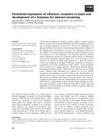
Bạn đang xem bản rút gọn của tài liệu. Xem và tải ngay bản đầy đủ của tài liệu tại đây (421.15 KB, 9 trang )
IEEE/ASME TRANSACTIONS ON MECHATRONICS, VOL. 12, NO. 3, JUNE 2007 265
Design and Development of a Medical Parallel Robot
for Cardiopulmonary Resuscitation
Yangmin Li, Senior Member, IEEE, and Qingsong Xu
Abstract—The concept of a medical parallel robot applicable to
chest compression in the process of cardiopulmonary resuscitation
(CPR) is proposed in this paper. According to the requirement of
CPR action, a three-prismatic-universal-universal (3-PUU) trans-
lational parallel manipulator (TPM) is designed and developed for
such applications, and a detailed analysis has been performed for
the 3-PUU TPM involving the issues of kinematics, dynamics, and
control. In view of the physical constraints imposed by mechanical
joints, both the robot-reachable workspace and the maximum in-
scribed cylinder-usable workspace are determined. Moreover, the
singularity analysis is carried out via the screw theory, and the
robot architecture is optimized to obtain a large well-conditioning
usable workspace. Based on the principle of virtual work with a
simplifying hypothesis adopted, the dynamic model is established,
and dynamic control utilizing computed torque method is imple-
mented. At last, the experimental results made for the prototype
illustrate the performance of the control algorithm well. This re-
search will lay a good foundation for the development of a medical
robot to assist in CPR operation.
Index Terms—Control, design theory, dynamics, medical robots,
parallel manipulators.
I. INTRODUCTION
I
N the case of a patient being in cardiac arrest, cardiopul-
monary resuscitation (CPR) must be applied in both rescue
breathing (mouth-to-mouth resuscitation) and chest compres-
sions. Generally, the compression frequency for an adult is
at the rate of about 100 times per minute with the depth of
4–5 cm using two hands, and the CPR is usually performed
with the compression-to-ventilation ratio of 15 compressions to
two breaths,
1
so as to maintain oxygenated blood flowing to
vital organs and to prevent anoxic tissue damage during cardiac
arrest [1]. Without oxygen, permanent brain damage or death
can occur in less than 10 min. Thus, for a large number of pa-
tients who undergo unexpected cardiac arrest, the only hope of
survival is timely application of CPR.
However, some patients in cardiac arrest may also be infected
with other indeterminate diseases, and hence, it is very danger-
ous for a doctor to apply CPR directly to them. For example,
before the severe acute respiratory syndrome (SARS) was first
recognized as a global threat in 2003, in many hospitals, such
kinds of patients were rescued as usual, and some doctors who
Manuscript received March 1, 2006; revised December 15, 2006 Recom-
mended by Guest Editors H P. Huang and F T. Cheng. This work was sup-
ported in part by the research committee of the University of Macau under
Grant RG068/05-06S/LYM/FST and in part by the Macao Science and Tech-
nology Development Fund under Grant 069/2005/A.
The authors are with the Department of Electromechanical Engineering, Fac-
ulty of Science and Technology, University of Macau, Macao SAR, China
(e-mail: ; ).
Digital Object Identifier 10.1109/TMECH.2007.897257
1
2003
had performed CPRon such patients were unfortunately infected
with the SARS corona virus [2]. In addition, chest compressions
consume a lot of energy from doctors; for instance, sometimes
it is necessary for ten doctors to work for 2 h to perform chest
compressions to rescue a patient in a Beijing, China, hospital.
Therefore, a medical robot that can be used for chest compres-
sions is urgently required. In view of this practical requirement,
we will design and develop a medical parallel robot to assist in
CPR operation and desire that the robot can perform this job
well instead of doctors.
A parallel manipulator generally consists of a moving plat-
form that is connected to a fixed base by several limbs or legs
in parallel. Nowadays, parallel manipulators are applied widely
since they possess many inherent advantages in terms of high
speed, high accuracy, high stiffness, and high load-carrying ca-
pacity over their serial counterparts. The enumeration of parallel
robots’ mechanical architectures and their versatile applications
can be found in [3] and [4], and some new architectures have
been proposed more recently in the literature [5]–[9].
In particular, parallel manipulators have great potential ap-
plications in medical fields, thanks to their fine characteristics
of stiffness, positioning accuracy, etc. For example, a new ap-
proach to robot-assisted spine and trauma surgery was presented
in [10] utilizing a designed 6-DOF parallel manipulator. Train-
ing for opening and closing of the mouth for the rehabilitation
of patients with problems of the jaw joint was suggested in [11]
using a 6-DOF parallel robot, and a 4-DOF parallel wire-driven
mechanism was presented in [12] with applications to leg reha-
bilitation, etc. However, to the authors’ knowledge, nothing in
the literature can be found that deals with parallel robots that
can be applyied in CPR assistance up to now.
The remainder of this paper is organized as follows. The
conceptual design of the medical robot system is proposed
in Section II. The kinematics analysis is carried out in Sec-
tion III, where the reachable workspace of the manipulator is
generated, and all the singularities are identified. Section IV
is focused on the optimal design of the robot architecture us-
ing a mixed performance index. The dynamic modeling and
dynamic control method are presented in Section V. Then, in
Section VI, the hardware development for the medical robot
is accomplished, and the experimental studies with a model-
based control algorithm are undertaken. Finally, this paper con-
cludes with a discussion of future research considerations in
Section VII.
II. C
ONCEPTUAL DESIGN OF A CPR ROBOT SYSTEM
A schematic of performing CPR is shown in Fig. 1, and a
conceptual design of the medical robot system is illustrated in
1083-4435/$25.00 © 2007 IEEE
266 IEEE/ASME TRANSACTIONS ON MECHATRONICS, VOL. 12, NO. 3, JUNE 2007
Fig. 1. Schematic of CPR operation.
Fig. 2. Conceptual design of a CPR medical robot system.
Fig. 2. As shown in Fig. 2, the patient is placed on a bed beside
a CPR robot, which is mounted on a separated movable base
via two supporting columns and is deposed above the chest of
the patient. The movable base can be moved anywhere on the
ground, and the supporting columns are extensible in the vertical
direction. Thus, the robot can be positioned well by hand such
that the chest compressions may start as soon as possible, which
also allows a doctor to easily take the robot away from the patient
in the case of any erroneous operation. Moreover, the CPR robot
is located on one side of the patient, thereby providing a free
space for a rescuer to access the patient on the other side.
In view of the high-stiffness and high-accuracy properties,
parallel mechanisms are employed to design such a manipulator
applicable to chest compressions in CPR. This idea is motivated
from the reason why the rescuer uses two hands instead of only
one hand to perform the action of chest compressions. In the
process of performing chest compressions, the two arms of the
rescuer construct a parallel mechanism. The main disadvantage
of parallel robots is their relatively limited workspace range.
Fortunately, by a proper design, a parallel robot is able to satisfy
the workspace requirement with a height of 4–5 cm for the CPR
operation.
In the next step comes the problem of how to select a particular
parallel robot for the application of CPR, since, nowadays, there
exist many parallel robots providing various types of output mo-
tions. An observation of the chest compressions in manual CPR
reveals that the most useful motion adopted in such an appli-
cation is the back-and-forth translation in a direction vertical
to the patient’s chest, whereas the rotational motions are almost
useless. Thus, parallel robots with a total of 6 DOF are not neces-
sarily required here. In addition, a 6-DOF parallel robot usually
possesses some disadvantages in terms of complicated forward
kinematics problems and highly coupled translation and rota-
tion motions, etc., which complicate the control of such robots.
Hence, translational parallel manipulators (TPMs) with only
three translational DOF in space are sufficient to be employed
in CPR operation. Because in addition to a translation, vertical
to the chest of the patient, a 3-DOF TPM can also provide trans-
lations in any other direction, this enables the adjustment of the
manipulator’s moving platform to a suitable position to perform
chest compression tasks. At this point, TPMs with less than 3
DOF are not adopted here.
As far as a 3-DOF TPM is concerned, it can be de-
signed as various architectures with different mechanical joints.
Many TPMs can be found in the literature [13]–[19]. In
some types of these TPMs, the first joint of each limb is lo-
cated at the base. In this case, since the actuators can be
mounted on the base, the moving components of the manip-
ulator do not bear any load of the actuators. This enables
large powerful actuators to drive relatively small structures,
facilitating the design of the manipulator with faster, stiffer,
and stronger characteristics. Several existing TPMs fall into
this category, such as the Delta and linear-Delta-architecture-
like TPMs [13]–[15], three-prismatic-universal-universal
(3-PUU) and three-revolute-universal-universal (3-RUU) mech-
anisms [16], etc.
From the economic point of view, the simpler the architecture
of a TPM, the lower will be the cost. In view of the complexity
of the TPM topology, including the number of mechanical joints
and links and their manufacture procedures, a 3-PUU TPM is
finally chosen and built utilizing the hardware available at the
Mechatronics Laboratory, University of Macau. It should be
noted that, theoretically, other architectures such as the Delta or
linear-Delta-like TPMs can also be employed in a CPR robot
system.
For the purposes of design and development of a 3-PUU med-
ical parallel robot for CPR applications, it is necessary to inves-
tigate the fundamental issues of the robot in terms of kinematic
modeling and optimization, workspace determination, dynamic
modeling, and so on, which will be performed in detail in the
following sections.
III. K
INEMATIC ANALYSIS OF THE MEDICAL ROBOT
A. Architecture Description
As shown in Figs. 2 and 3, the 3-PUU TPM consists of a
moving platform, a fixed base, and three limbs with identical
kinematic structure. Each limb connects the fixed base to the
moving platform by a prismatic (P) joint followed by two uni-
versal (U) joints in sequence, where the P joint is driven by a
linear actuator. In view of the cost effectiveness, the linear ac-
tuator is implemented by using a lead screw actuation system
driven by a dc servomotor in this paper. For safety reasons, the
selected screw should satisfy the condition of self-locking, i.e.,
the lead angle of the lead screw is less than the angle of friction,
so as to ensure that the nut is self-locking when the lead screw is
LI AND XU: DESIGN AND DEVELOPMENT OF A MEDICAL PARALLEL ROBOT FOR CARDIOPULMONARY RESUSCITATION 267
Fig. 3. Representation of vectors and joint axes for the ith limb.
not actuated. It should be noted that if other types of linear ac-
tuators are selected, they should not be back-drivable for safety
reasons as well.
Similar to a 3-UPU platform [18], [19], it can be demonstrated
that a 3-PUU mechanism can be arranged to achieve 3-DOF
translational motion with certain geometric conditions satisfied.
Briefly, in each kinematic chain, the first revolute joint axis is
parallel to the last revolute joint axis, and the two intermediate
joint axes are parallel to each other, i.e., the unit vectors of
joint axes s
3i
= s
4i
and s
2i
= s
5i
(i =1, 2, and 3), as shown in
Fig. 3.
For the sake of analysis, we assign a fixed Cartesian reference
frame O{x, y, z} at the center point O of the fixed base platform
∆A
1
A
2
A
3
,andamovingframeP {u, v, w} on the moving
platform at the center point P of triangle ∆B
1
B
2
B
3
. In addition,
let the x- and u-axes be parallel to each other, and the x-axis be
direct along
−−→
OA
1
. The angle between vectors
−−→
OA
i
and
−−→
PB
i
is
defined as the twist angle θ, i.e., the angle between the moving
and base platforms. In addition, the three rails D
i
E
i
intersect the
x − y plane at points A
1
, A
2
, and A
3
that lie on a circle of radius
a. The three links C
i
B
i
with the length of l intersect the u − v
plane at points B
1
, B
2
, and B
3
, which lie on a circle of radius
b. Angle α is measured from the fixed base to rails D
i
E
i
and
is defined as the layout angle of actuators. In order to achieve a
symmetric workspace of the manipulator, both ∆A
1
A
2
A
3
and
∆B
1
B
2
B
3
are assigned to be equilateral triangles.
Additionally, the joint axis orientations of s
2i
and s
5i
are
assembled to be perpendicular to the rail direction
−−− →
D
i
E
i
and lie
in a plane defined by vectors
−−→
OA
i
and
−−− →
D
i
E
i
. Joint axes s
3i
and
s
4i
are all perpendicular to the leg direction of
−−−→
C
i
B
i
.
B. Kinematic Modeling
Let l
i0
be a unit vector along the leg C
i
B
i
, d
i
represents
a linear displacement of the ith actuator, and d
i0
denotes the
corresponding unit vector pointing along rail D
i
E
i
. Also, let
a
i
=
−−→
OA
i
, b
i
=
−−→
PB
i
, and p =
−−→
OP =[xyz]
T
. With reference
to Fig. 3, a vector-loop equation can be written for the ith limb
l l
i0
= l
i
− d
i
d
i0
(1)
where l
i
= p + b
i
− a
i
.
Considering a lead screw actuation system, the rotation θ
i
of
the lead screw can be converted to the linear displacement d
i
of
the nut as
d
i
= pθ
i
/(2π) (2)
where p denotes the thread lead of the lead screw.
The inverse kinematics problem calculates the actuated vari-
ables from a given position of the moving platform, which can
be easily solved in the closed form with the consideration of (1)
and (2). On the other hand, given a set of actuated inputs, the
moving platform position is solved by the forward kinematics.
Similar to most of the 3-DOF TPMs [14], the forward kinematics
of a 3-PUU TPM can be solved by determining the intersection
of three spheres, and more details can be found in [20].
Differentiating (1) with respect to time and eliminating pas-
sive variables, one can generate [21]
J
q
˙
q = J
x
˙
x (3)
where
J
q
=
l
T
10
d
10
00
0 l
T
20
d
20
0
00l
T
30
d
30
, J
x
=
l
T
10
l
T
20
l
T
30
(4)
and
˙
q =[
˙
d
1
˙
d
2
˙
d
3
]
T
is the vector of linear actuated joint rates.
When the manipulator is away from singularities, from (3), we
can obtain that
˙
q = J
˙
x (5)
where J = J
−1
q
J
x
is the 3 × 3 Jacobian matrix of a 3-PUU TPM,
which relates the output velocities to the actuated joint rates.
C. Workspace Determination
In the design of a 3-PUU TPM, the physical constraints
in terms of motion limits of mechanical joints, interference
between links and the surrounding, self-collision, etc., should
be taken into account. For the sake of brevity, we only consider
the translational limits of the actuated P joints and rotational
limits of the passive U joints and assume that the interference
and collision problems can be avoided by restricting the motion
limits of the mechanical joints.
Let the translational limits of actuated P joints be ±S, i.e.,
−S ≤ d
i
≤ S (i =1, 2, 3), and the rotational limits of passive
U joints be ±ϕ, which forms a pyramid-shaped range for each
leg. In view of the fact that the moving platform is parallel to the
base platform, it is clear that the constraint motion of point P
induced by the ith limb can be derived from the possible motion
of point B
i
by a constant translation of vector
−−→
B
i
P . Hence,
the TPM workspace can be determined as the intersection of
the possible motion range of B
i
, i.e., the workspace of each
leg [20].
Assume that S =50 mm and ϕ =22
◦
, the reachable
workspace of a 3-PUU TPM with the architectural parameters
described in Table I is sketched in Fig. 4, which is generated by
utilizing a geometric approach. It can be noticed that the cross
section of the workspace can also be calculated exactly by using
Green’s theorem [22].
268 IEEE/ASME TRANSACTIONS ON MECHATRONICS, VOL. 12, NO. 3, JUNE 2007
TAB LE I
A
RCHITECTURAL PARAMETERS OF A 3-PUU TPM
Fig. 4. Reachable workspace of a 3-PUU TPM. (a) 3-D view. (b) Cross sec-
tions at different heights. (c) Top view.
It can be observed that the workspace is 120
◦
symmetrical
about the three linear actuators’ motion directions from up to
down view. In the upper and lower ranges of the workspace, the
cross section has the triangular shape, while in the dominated
middle range, the cross-sectional shape looks like a hexagon.
D. Singularity Identification
The identification of singularities is important both for
singularity-free path planning and control implementation there-
after. Usually, the singularity analysis of a parallel robot can be
successfully performed based on the rank deficiency of the Ja-
cobian matrix [21]. However, similar to a 3-UPU platform [23],
[24], the 3 × 3 Jacobian (J) for a 3-PUU TPM is not sufficient to
predict all the singularities including the architecture singular-
ity [23] and constraint singularity [25]. In contrast, the singular
configurations can be fully identified by resorting to the screw
theory as reported in [26].
With υ and ω respectively denoting the vectors for the linear
and angular velocities, the twist of the moving platform can be
defined as T =[υ
T
ω
T
]
T
in Pl
¨
ucker axis coordinate. Concern-
ing a 3-PUU TPM, the connectivity of each limb is equal to five,
and hence, the instantaneous twist T of the moving platform can
be expressed as a linear combination of the five instantaneous
twists, i.e.
T =
˙
d
i
ˆ
T
1i
+
˙
θ
2i
ˆ
T
2i
+
˙
θ
3i
ˆ
T
3i
+
˙
θ
4i
ˆ
T
4i
+
˙
θ
5i
ˆ
T
5i
(6)
for i =1, 2, and 3, where
˙
θ
ji
is the intensity, and
ˆ
T
ji
denotes
a unit screw associated with the jth joint of the ith limb, and
ˆ
T
1i
=
d
i0
0
,
ˆ
T
2i
=
c
i
× s
2i
s
2i
,
ˆ
T
3i
=
c
i
× s
3i
s
3i
,
ˆ
T
4i
=
b
i
× s
4i
s
4i
,
ˆ
T
5i
=
b
i
× s
5i
s
5i
can be identified, where 0 denotes a 3 × 1 zero vector, s
ji
rep-
resents a unit vector along the jth joint axis of the ith limb, and
c
i
= b
i
− l l
i0
.
Firstly, it follows that one screw
ˆ
t
ci
(expressed in Pl
¨
ucker ray
coordinate) that is reciprocal to all the joint screws of the ith
limb forms a one-system, and can be identified as an infinite
pitch screw with a direction perpendicular to the two joint axes
of a U joint, i.e.,
ˆ
t
ci
=
0
r
i
(7)
where r
i
is a unit vector along the direction defined by s
2i
× s
3i
(or s
5i
× s
4i
), as shown in Fig. 3.
Taking the reciprocal product of both sides of (6) with
ˆ
t
ci
and
rewriting the results into the matrix form, yields
J
c
T = 0 (8)
where
J
c
=
0r
T
1
0r
T
2
0r
T
3
3×6
(9)
is called the Jacobian of constraints [26].
Each row in J
c
denotes a moment of constraints imposed by
the joints of a limb, the combination of which constrains the
moving platform a 3-DOF motion. Hence, if the three moments
with directions of r
i
are linearly independent, the unique solu-
tion to (8) is ω = 0, which means the absence of the rotational
DOF. However, if the three moments lie on a common plane or
are parallel to one another, the TPM will be under constraint
singularity, where the TPM gets additional rotational DOF. The
existence of constraint singularity can be verified by checking
whether the determinant of J
c
vanishes or not.
Secondly, with the actuators locked, the reciprocal screws
of each limb form a two-system which includes the screw
ˆ
t
ci
identified earlier. One additional basis screw
ˆ
t
ai
being reciprocal
to all the passive joint screws of the ith limb can be identified
as a zero pitch screw along the direction passing through the
centers of the two U joints
ˆ
t
ai
=
l
i0
b
i
× l
i0
. (10)
Similarly, taking the reciprocal product on both sides of (6)
with
ˆ
t
ai
, results in
J
a
T = J
q
˙
q (11)
where J
q
is the inverse Jacobian, as expressed in (4),
˙
q =
[
˙
d
1
˙
d
2
˙
d
3
]
T
denotes the actuated joint rates, and
J
a
=
l
T
10
(b
1
× l
10
)
T
l
T
20
(b
2
× l
20
)
T
l
T
30
(b
3
× l
30
)
T
3×6
(12)
is defined as the Jacobian of actuation.
Each row in J
a
denotes a force of actuation contributing along
a leg. Once the three forces with directions of l
i0
are linear-
dependent, the TPM will be under architecture singularity. It
is the case when the three legs lie on a common plane or are
parallel to each other. Under this type of singularity, with the
LI AND XU: DESIGN AND DEVELOPMENT OF A MEDICAL PARALLEL ROBOT FOR CARDIOPULMONARY RESUSCITATION 269
actuators locked, the moving platform of the TPM can still
undergo infinitesimal translations.
In addition, the inverse singularity will occur in case if the
Jacobian J
q
is not of full rank. From (4), one can see that this
is the case of l
T
i0
d
i0
=0for i =1, 2, or 3, i.e., the directions of
one or more of legs are perpendicular to the axial directions of
the corresponding actuated joints. In such situations, the moving
platform loses one or more DOF.
Furthermore, associating (8) with (11) allows the generation
of
˙
q
o
= J
o
T (13)
where
˙
q
o
=[
˙
d
1
˙
d
2
˙
d
3
000]
T
is a vector of expanded joint
rates, and
J
o
=
J
−1
q
J
a
J
c
(14)
is called the 6 × 6 overall Jacobian of a 3-PUU TPM, which
can be employed to evaluate all the singularity properties of the
TPM.
IV. A
RCHITECTURE OPTIMIZATION FOR A LARGE
SINGULARITY-FREE USABLE WORKSPACE
To design a parallel robot, there are many factors that have
to be taken into account [27]–[29]. In order to design a medical
robot, the safety of the patient is the first and foremost issue
needed to be kept in mind. As far as the design criteria for a
3-PUU medical parallel robot are concerned, the most important
issue is to design the medical robot without singularities within
its workspace. Because the singularity results in the loss of
controllability of the robot, under such situations, the patient will
probably be harmed. Another issue that needs to be considered is
the accuracy of the robot, which can be mainly solved by means
of calibration. In this section, the architecture of the medical
robot will be optimized to generate a large usable workspace
excluding the singularities.
It is known that the conditioning index (CI) is defined as the
reciprocal of the condition number of the Jacobian matrix [30],
[31], that is,
µ =
1
κ
(15)
where κ denotes the condition number of the Jacobian matrix.
However, a problem arises for the condition number as far as
the units of elements in the Jacobian matrix are concerned.
An observation of the Jacobian J
o
in (14) reveals that the first
three columns are dimensionless while the last three columns
have the unit of length. In order to homogenize the dimension
of the overall Jacobian, the last three columns can be divided
by the radius of the moving platform [32], thus, leading to a
homogeneous overall Jacobian for a 3-PUU TPM
J
oh
=
J
ah
J
c
(16)
where J
ah
= J
−1
q
J
a
d, with d = diag{111
1
b
1
b
1
b
}.
The CI is bounded between 0 (singularity) and 1 (isotropy),
and measures the degree of ill-conditioning of the Jacobian
Fig. 5. Determination of cylinder-usable workspace U. (a) 3-D view. (b) x–z
section view.
matrix, i.e., closeness of the singularity. Thus, CI can be used
to evaluate the singularity of a manipulator. In the design of the
medical robot, it is expected that singular configurations are far
away from the manipulator workspace, which can be satisfied
by ensuring that the CI values over the workspace are all larger
than a specified value.
In addition, a global dexterity index (GDI) is given in [31]
ε =
V
µdV
V
(17)
where V is the total workspace volume. The GDI describes the
uniformity of manipulability over the entire workspace and can
also be adopted to evaluate the conditioning of the Jacobian
matrix.
A. Determination of the Maximum Usable Workspace
A visualization of CI distribution in the planes at different
heights within the workspace reveals that the worst CI occurs
around the boundary of the lowest plane. This comes from the
reason that the manipulator approaches singularity when it is
near the workspace boundary. Thus, it is reasonable to restrict
the manipulator to perform tasks in a usable workspace, i.e.,
a subworkspace located within the reachable workspace. Con-
cerning a 3-PUU TPM for the CPR medical application, we
define the usable workspace as the maximum inscribed cylinder
inside the reachable workspace with its central axis along the
z-axis direction.
The determination procedure for such a cylinder usable
workspace (U ) with the radius R and height H is illustrated
in Fig. 5. It is observed that the workspace U inscribed in the
reachable workspace at six points of K
D
i
and K
E
i
(i =1, 2, 3),
which lie on the surfaces of the six spheres centered at D
i
and
E
i
, respectively. The volume of U can be calculated by
V
U
= πR
2
H = πR
2
(z
1
− z
2
) (18)
where z
1
= Ssα − [l
2
− (R − a − Scα + b)
2
]
1/2
and z
2
=
−Ssα − [l
2
− (R + a − Scα − b)
2
]
1/2
, with sα =sin(α) and
cα =cos(α), respectively.
270 IEEE/ASME TRANSACTIONS ON MECHATRONICS, VOL. 12, NO. 3, JUNE 2007
For any 3-PUU TPM, the maximum volume of the usable
workspace arises in the case of
∂V
U
∂R
=0, which represents an
equation in a single variable R and allows the calculation of the
values of R and H in sequence.
B. Design Variables and Objective Function
The architectural parameters of a 3-PUU TPM involve the
sizes of base platform (a) and moving platform (b), length of
legs (l), layout angle of actuators (α), and the twist angle (θ).
To obtain a symmetric workspace, the twist angle is designed
as θ =0
◦
, and in order to perform the architecture optimization
independent of the dimension of each design candidate, the first
three parameters are scaled by S, i.e., the half stroke of linear
actuators. Thus, the design variables become
a
S
,
b
S
,
l
S
, and α.
Additionally, to ensure a real geometry of the robot, the design
variables are restricted within the parameter spaces of [0.55.0],
[0.55.0], [1.05.0], and [0
◦
90
◦
], respectively.
Regarding the physical constraints, the rotational limits of U
joints are ϕ =22
◦
, the motion range limits of P joints are ±S,
and the home position of the moving platform is assigned as the
middle stroke of linear actuators, i.e., d
i
=0(i =1, 2, 3).
The optimization objective for the 3-PUU medical parallel
robot is to obtain a usable workspace with the best condition-
ing. The objective function for maximization is defined as the
minimum value of a mixed index, which is a weighted sum of
CI (µ) and GDI (ε) over the whole usable workspace (U)
f(n) = min
i∈U
w
c
µ
i
+(1− w
c
)ε
i
(19)
where n =
a
S
b
S
l
S
α
T
are the design variables, and the
weight parameter w
c
describes the proportion of CI in the mixed
index.
C. Computational Issues and Optimization Results
In the optimal design to search a robot geometry with the
maximum value of objective function f(n), the search space,
i.e., the parameter space, of each design variable is sampled at
regular intervals. Each sampling node represents the geometry of
a particular robot. The performance of the robot corresponding
to each node is evaluated by the mixed index.
Considering the CI distributions within the reachable
workspace, i.e., the minimal CI value occurs on the circular
boundary of the usable workspace bottom, the overall perfor-
mance is evaluated on the two end circular planes of the usable
workspace by a discretization method. Each plane is sampled
in terms of radius and angle in a polar coordinate, where one
circle is sampled by the interval of 60
◦
. This is reasonable since
the distributions of CI inside the workspace have a symmetry at
120
◦
just similar to the shape of workspace, and the radius (R)
of the usable workspace is sampled as five line segments.
In addition, the design parameters of
a
S
,
b
S
,
l
S
, and α are sam-
pled by the interval of 0.5, 0.5, 0.5, and 15
◦
, respectively. The op-
timization is carried out on a personal computer (Intel Pentium
4 CPU 3.00-GHz, 512-MB RAM) with Microsoft Windows XP
operating system. For the optimization with a particular weight
number (w
c
), the computational time is about 2.0 h, and the nu-
merical results for w
c
=0.5 are:
a
S
=4.5,
b
S
=0.5,
l
S
=5.0,
and α =30
◦
, which leads to a robot with the usable workspace
defined by R =0.83S and H =1.10S. According to these pa-
rameters relationships, a 3-PUU TPM can be designed to have
a predefined size of the cylinder-usable workspace.
It is noticeable that the computational time of the optimization
increases exponentially as the reducing of the interval sizes to get
more accurate results, while optimization time may be reduced
by other design approaches such as the interval analysis [27],
genetic algorithm [29], etc.
V. D
YNAMIC MODELING AND CONTROL ALGORITHM
A. Dynamic Modeling
The main issue in dynamic analysis for a parallel robot is
to develop an inverse dynamic model, which enables the com-
putation of the required actuator forces and/or torques when
a desired trajectory of the moving platform is given. In what
follows, we will perform the dynamic modeling of the 3-PUU
TPM via the virtual work principle.
1) Simplification Hypothesis: As for a 3-PUU TPM, similar
to a 3-PRS parallel manipulator [33], the complexity of the
dynamic model partly comes from the three moving legs. Since
the legs can be built with light materials such as aluminium
alloy, the dynamic problem can be simplified by the following
hypotheses: the rotational inertias of legs are neglected; the mass
of each leg is equally divided into two portions and placed at its
two extremities.
Let m
p
, m
s
, and m
l
denote the mass of the moving platform,
a nut and a leg, respectively. Then, the equivalent mass of the
nut and the moving platform respectively becomes ˆm
s
= m
s
+
1
2
m
l
and ˆm
p
= m
p
+
3
2
m
l
.
2) Dynamic Modeling: The torque τ =[τ
1
τ
2
τ
3
]
T
of the
lead screw can be converted to the force f =[f
1
f
2
f
3
]
T
acting
on the nut approximately by [34]
f =2τ /(µ
c
d
s
) (20)
where µ
c
denotes the friction coefficient, and d
s
represents the
pitch diameter of the lead screw.
Let δq =[δd
1
δd
2
δd
3
]
T
and δx =[δp
x
δp
y
δp
z
]
T
be the
vectors for virtual linear displacements of the nuts and moving
platform, respectively. Applying the principle of virtual work
allows the derivation of the following equation by neglecting
the friction forces in passive U joints and assuming that there
are no external forces suffered:
f
T
δq + G
T
s
δq − f
T
s
δq + G
T
p
δx − f
T
p
δx =0 (21)
where G
s
=ˆm
s
gsαdiag{111} is the vector of gravity forces
of the nuts with g representing the gravity acceleration, G
p
=
[0 0 ˆm
p
g]
T
is the gravity force vector of the moving platform,
f
s
=ˆm
s
[
¨
d
1
¨
d
2
¨
d
3
]
T
is the vector of inertial forces of the nuts,
and f
p
=ˆm
p
[¨p
x
¨p
y
¨p
z
]
T
is the vector of inertial forces of the
moving platform.
With the substitution of (5) into (21) and a careful treatment,
one can obtain that
f = M
s
¨
q + J
−T
M
p
¨
x − G
s
− J
−T
G
p
(22)
LI AND XU: DESIGN AND DEVELOPMENT OF A MEDICAL PARALLEL ROBOT FOR CARDIOPULMONARY RESUSCITATION 271
Fig. 6. Block diagram of joint space dynamic control for a 3-PUU TPM.
where M
s
=ˆm
s
diag{111} and M
p
=ˆm
p
diag{111}.
Then, substituting (5) into (22) and in view of (2) and (20),
results in the joint space dynamic model of a 3-PUU TPM:
τ = M(θ)
¨
θ + c(θ,
˙
θ)
˙
θ + G(θ) (23)
where
M(θ) ≡
µ
c
d
s
p
4π
M
s
+ J
−T
M
p
J
−1
∈ R
3×3
(24)
c(θ,
˙
θ) ≡
µ
c
d
s
p
4π
J
−T
M
p
˙
J
−1
∈ R
3×3
(25)
G(θ) ≡−
µ
c
d
s
2π
G
s
+ J
−T
G
p
∈ R
3
(26)
with θ =[θ
1
θ
2
θ
3
]
T
∈ R
3
denoting the controlled variables,
M(θ) denoting a symmetric positive definite inertial matrix,
c(θ,
˙
θ) representing the matrix of centrifugal and Coriolis
forces, and G(θ) describing the vector of gravity forces.
B. Dynamic Control Algorithm
The dynamic control in joint space utilizing the computed
torque method is implemented for a 3-PUU TPM in this paper.
Firstly, the joint space dynamic model (23) can be rewritten into
the form
f = M(θ)
¨
θ + H(θ,
˙
θ) (27)
where H(θ,
˙
θ)=c(θ,
˙
θ)
˙
θ + G(
˙
θ).
Fig. 6 represents a block diagram of the computed torque con-
trol system with proportional derivative (PD) feedback. Assum-
ing that there are no external disturbances, then the manipulator
is actuated with the following vector of joint forces:
f =
ˆ
M(θ)u +
ˆ
H(θ,
˙
θ) (28)
where u is an input signal vector in the form of acceleration, and
ˆ
M(θ) and
ˆ
H(θ,
˙
θ) denote the estimators of the inertial matrix
M(θ) and the nonlinear coupling matrix H(θ,
˙
θ) implemented
in the controller, respectively.
Combining (27) with (28) results in the following linear
second-order system:
¨
θ = u. (29)
The obtained linear system allows the specification of the nec-
essary feedback gains as well as the reference signal required
for a desired motion task, and the reference signal is defined
according to the following algorithm [35]:
r =
¨
θ
d
+ K
D
˙
θ
d
+ K
P
θ
d
(30)
Fig. 7. Photograph of a 3-PUU medical parallel robot prototype.
where θ
d
denotes the desired joint trajectory, and K
P
and
K
D
represent the symmetric positive–definite feedback gain
matrices.
The acceleration input signal in (29) then becomes
u = r − K
D
˙
θ − K
P
θ
=
¨
θ
d
+ K
D
(
˙
θ
d
−
˙
θ)+K
P
(θ
d
− θ). (31)
Substituting (31) into (29), leads to the equation of errors
¨
e + K
D
˙
e
d
+ K
P
e =0 (32)
where e = θ
d
− θ is the vector of joint tracking errors, which
will go to zero asymptotically by specifying appropriate values
of feedback gains K
P
and K
D
.
VI. E
XPERIMENTS ON THE PROTOTYPE
A prototype of a 3-PUU medical parallel robot is shown in
Fig. 7, which was built in the Mechatronics Laboratory, Univer-
sity of Macau. The nominal kinematic and dynamic parameters
of the robot prototype are described in Tables I and II, respec-
tively, and the robot workspace is depicted in Fig. 4. It can
be observed that the reachable workspace height is 152.1 mm
and the usable workspace height can be calculated as 48.9 mm
(with R =45.7 mm), which is adequate for the CPR oper-
ation. It should be mentioned that this initial prototype is de-
signed with respect to the performance of GDI and spatial utility
ratio index according to [20], and the prototype is used here to
validate the adopted model-based control algorithm with the
dynamic modeling hypotheses.
272 IEEE/ASME TRANSACTIONS ON MECHATRONICS, VOL. 12, NO. 3, JUNE 2007
TAB LE II
D
YNAMIC PARAMETERS OF THE 3-PUU TPM
Fig. 8. Configuration of the experimental system setup.
Fig. 8 illustrates the hardware allocations and connections of
the experimental system. The dynamic control algorithm has
been implemented using a developed Visual C++ program
running on a personal computer, and the three dc servomo-
tors (from CM Technology, LLC) are controlled by a motion
controller DCT0040 (from DynaCity Technology, Hong Kong,
Ltd.), which is connected to the computer through a RS485 high-
speed connection for the safety reason. The DCT0040 controller
integrates motion control and servo amplifier into one unit to
achieve space saving and to reduce wiring complexity, and is
able to provide a good motion performance utilizing advanced
digital signal processing (DSP) and field-programmable gate
array (FPGA) technologies. The sampling frequency is 20 kHz.
The dynamic control is carried out such that the moving
platform can track the following trajectory:
p
x
= −30 sin(πt) (33a)
p
y
=30cos(πt) (33b)
p
z
= −110 + 20 cos(πt/2) (33c)
where t is the time variable in seconds, and p
x
, p
y
, and p
z
are in millimeters. In the control procedure, the trajectory in
task space is first translated into the joint space through in-
verse kinematic solutions, and the feedback gains are set as
K
P
= 625 diag{111} and K
D
=50diag{111}, respectively.
The experimental results for the joint errors are plotted in Fig. 9.
It can be observed that the tracking errors converge to almost
steady zero errors only after about 0.3 s. The experimental re-
sults illustrate not only the applicability of the adopted control
algorithm but also the rationality of the introduced simplifying
hypothesis for the dynamic modeling process.
Fig. 9. Experimental results of dynamic control method.
VII. CONCLUSION
In this paper, a novel concept of employing a medical parallel
robot for chest compressions in the process of CPR operation
has been proposed. In view of the requirements from medical
aspects, a 3-PUU translational parallel manipulator was chosen
and designed to satisfy the specific requirement.
The kinematic analysis was performed and the manipulator-
reachable workspace was generated by taking into account the
physical constraints introduced by the rotational limits of univer-
sal joints and motion ranges of prismatic joints. Moreover, the
usable workspace was also determined, which is defined as the
maximum inscribed cylinder inside the reachable workspace,
and all of the singular configurations are identified by means of
the screw-theory approach. Furthermore, the optimal design is
implemented based on a mixed index of the CI and GDI. The op-
timization leads to a robot possessing a large well-conditioning
usable workspace excluding singularities. Then, by adopting a
simplification hypothesis, the inverse dynamic model was es-
tablished via the approach of virtual work principle, and the
model-based control with PD feedback has been implemented.
Experimental results illustrate both the validity of the adopted
simplifying hypothesis and the good performance of the em-
ployed control algorithm.
The investigations presented here provide a sound base to
develop a new medical robot to assist in CPR operation, which
can significantly reduce the risk and workload of doctors in
rescuing patients. Our further work will involve implementing
animal experiments and clinical application for patients and es-
tablishing system models with the consideration of interactions
between the moving platform and the human body to ensure that
no harm will be happened to the ribs and heart of the patient.
Furthermore, some monitoring sensors will also be used to de-
tect whether the patient is awake or not so as to stop the CPR
operation on time.
R
EFERENCES
[1] I. N. Bankman, K. G. Gruben, H. R. Halperin, A. S. Popel, A. D. Guerci,
and J. E. Tsitlik, “Identification of dynamic mechanical parameters of the
human chest during manual cardiopulmonary resuscitation,” IEEE Trans.
Biomed. Eng., vol. 37, no. 2, pp. 211–217, Feb. 1990.
[2] T Q. Lou, X. Liu, X G. Bi, K X. Zhang, and Q F. Xie, “Analysis on
diagnosis and treatment with integrated traditional Chinese and western
medicine in 20 severe acute respiratory syndrome patients infected in
LI AND XU: DESIGN AND DEVELOPMENT OF A MEDICAL PARALLEL ROBOT FOR CARDIOPULMONARY RESUSCITATION 273
hospital,” Chin. J. Integr. Traditional West. Med. Intensive Crit. Care,
vol. 10, no. 4, pp. 211–213, 2003.
[3] L. W. Tsai, Robot Analysis: The Mechanics of Serial and Parallel Manip-
ulators. New York: Wiley, 1999.
[4] J P. Merlet, Parallel Robots. London, U.K.: Kluwer, 2000.
[5] Y. Fang and L. W. Tsai, “Structure synthesis of a class of 4-DoF and 5-DoF
parallel manipulators with identical limb structures,” Int. J. Robot. Res.,
vol. 21, no. 9, pp. 799–810, 2002.
[6] X J. Liu and J. Wang, “Some new parallel mechanisms containing the
planar four-bar parallelogram,” Int. J. Robot. Res., vol. 22, no. 9, pp. 717–
732, 2003.
[7] M. Carricato and V. Parenti-Castelli, “Kinematics of a family of transla-
tional parallel mechanisms with three 4-DOF legs and rotary actuators,”
J. Robot. Syst., vol. 20, no. 7, pp. 373–389, 2003.
[8] R. Di Gregorio, “A new family of spherical parallel manipulators,” Robot-
ica, vol. 20, no. 4, pp. 353–358, 2002.
[9] X J. Liu, J. Wang, and G. Pritschow, “A new family of spatial 3-DoF
fully-parallel manipulators with high rotational capability,” Mech. Mach.
Theory, vol. 40, no. 4, pp. 475–494, 2005.
[10] M. Shoham, E. Zehavi, L. Joskowicz, E. Batkilin, and Y. Kunicher, “Bone-
mounted miniature robot for surgical procedures: Concept and clinical
applications,” IEEE Trans. Robot. Autom., vol. 19, no. 5, pp. 893–901,
Oct. 2003.
[11] H. Takanobu, T. Maruyama, A. Takanishi, K. Ohtsuki, and M. Ohnishi,
“Mouth opening and closing training with 6-DOF parallel robot,” in Proc.
IEEE Int. Conf. Robot. Autom., San Francisco, CA, 2000, pp. 1384–1389.
[12] K. Homma, O. Fukuda, J. Sugawara, Y. Nagata, and M. Usuba, “A wire-
driven leg rehabilitation system: Development of a 4-DOF experimental
system,” in Proc. IEEE/ASME Int. Conf. Adv. Intell. Mechatron., Kobe,
Japan, 2003, pp. 908–913.
[13] R. Clavel, “Delta, a fast robot with parallel geometry,” in Proc. 18th Int.
Symp. Ind. Robots, Lausanne, Switzerland, 1988, pp. 91–100.
[14] L. W. Tsai, G. C. Walsh, and R. E. Stamper, “Kinematics of a novel three
DOF translational platform,” in Proc. IEEE Int. Conf. Robot. Autom.,
Minneapolis, MN, 1996, pp. 3446–3451.
[15] D. Chablat, P. Wenger, F. Majou, and J P. Merlet, “An interval analysis
based study for the design and the comparison of 3 DOF parallel kinematic
machines,” Int. J. Robot. Res., vol. 23, no. 6, pp. 615–624, 2004.
[16] L. W. Tsai and S. Joshi, “Kinematics analysis of 3-DOF position mech-
anisms for use in hybrid kinematic machines,” ASME J. Mech. Des.,
vol. 124, no. 2, pp. 245–253, 2002.
[17] Y. Li and Q. Xu, “Kinematic analysis and design of a new 3-DOF trans-
lational parallel manipulator,” ASME J. Mech. Des., vol. 128, no. 4,
pp. 729–737, 2006.
[18] L. W. Tsai, “Kinematics of a three-DOF platform with three extensi-
ble limbs,” in Recent Advances in Robot Kinematics, J. Lenarcic and
V. Parenti-Castelli, Eds. Norwell, MA: Kluwer, 1996, pp. 401–410.
[19] R. Di Gregorio and V. Parenti-Castelli, “A translational 3-DOF parallel
manipulator,” in Advances in Robot Kinematics: Analysis and Control,
J. Lenarcic and M. L. Husty, Eds. Norwell, MA: Kluwer, 1998, pp. 49–
58.
[20] Y. Li and Q. Xu, “A new approach to the architecture optimization of a
general 3-PUU translational parallel manipulator,” J. Intell. Robot. Syst.,
vol. 46, no. 1, pp. 59–72, 2006.
[21] C. Gosselin and J. Angeles, “Singularity analysis of closed-loop kinematic
chains,” IEEE Trans. Robot. Autom., vol. 6, no. 3, pp. 281–290, Jun. 1990.
[22] C. Gosselin, “Determination of the workspace of 6-DOF parallel manip-
ulators,” ASME J. Mech. Des., vol. 112, no. 3, pp. 331–336, 1990.
[23] R. Di Gregorio and V. Parenti-Castelli, “Mobility analysis of the 3-UPU
parallel mechanism assembled for a pure translational motion,” ASME J.
Mech. Des., vol. 124, no. 2, pp. 259–264, 2002.
[24] A. Wolf, M. Shoham, and F. C. Park, “Investigation of the singularities
and self-motions of the 3-UPU robot,” in Advances in Robot Kinematics,
J. Lenarcic and F. Thomas, Eds. Norwell, MA: Kluwer, 2002, pp. 165–
174.
[25] D. Zlatanov, I. A. Bonev, and C. M. Gosselin, “Constraint singulari-
ties of parallel mechanisms,” in Proc. IEEE Int. Conf. Robot. Autom.,
Washington, DC, 2002, pp. 496–502.
[26] S. A. Joshi and L. W. Tsai, “Jacobian analysis of limited-DOF parallel
manipulators,” ASME J. Mech. Des., vol. 124, no. 2, pp. 254–258, 2002.
[27] F. Hao and J P. Merlet, “Multi-criteria optimal design of parallel manip-
ulators based on interval analysis,” Mech. Mach. Theory, vol. 40, no. 2,
pp. 157–171, 2005.
[28] X J. Liu, “Optimal kinematic design of a three translational DoFs parallel
manipulator,” Robotica, vol. 24, no. 2, pp. 239–250, 2006.
[29] D. Zhang, Z. Xu, C. M. Mechefske, and F. Xi, “Optimum design of parallel
kinematic toolheads with genetic algorithms,” Robotica, vol. 22, no. 1,
pp. 77–84, 2004.
[30] T. Yoshikawa, “Manipulability of robotic mechanisms,” Int. J. Robot.
Res., vol. 4, no. 2, pp. 3–9, 1985.
[31] C. Gosselin and J. Angeles, “A global performance index for the kinematic
optimization of robotic manipulators,” ASME J. Mech. Des., vol. 113,
no. 3, pp. 220–226, 1991.
[32] O. Ma and J. Angeles, “Optimum architecture design of platform manip-
ulators,” in Proc. IEEE Int. Conf. Adv. Robot., Pisa, Italy, 1991, pp. 1130–
1135.
[33] Y. Li and Q. Xu, “Kinematics and inverse dynamics analysis for a general
3-PRS spatial parallel mechanism,” Robotica, vol. 23, no. 2, pp. 219–229,
2005.
[34] R. J. Eggert, “Power screws,” in Standard Handbook of Machine Design,
J. E. Shisley and C. R. Mischke, Eds. New York: McGraw-Hill, 1996.
[35] J. J. Craig, Introduction to Robotics: Mechanics and Control, 2nd ed.
Reading, MA: Addison-Wesley, 1989.
Yangmin Li (M’98–SM’04) received the B.S. and
M.S. degrees from Jilin University, Changchun,
China, in 1985 and 1988, respectively, and the Ph.D.
degree from Tianjin University, Tianjin, China, in
1994, all in mechanical engineering.
He was with South China University of Technol-
ogy, the International Institute for Software Technol-
ogy of the United Nations University (UNU/IIST),
the University of Cincinnati, and Purdue University.
He is currently an Associate Professor of robotics,
mechatronics, control, and automation at the Univer-
sity of Macau, Macao SAR, China. He has authored or coauthored about 160
papers published in international journals and conference proceedings.
Dr. Li is a member of the American Society of Mechanical Engineers
(ASME). Since 2004, he has been a Council Member and an Editor of the
Chinese Journal of Mechanical Engineering.
Qingsong Xu received the B.S. degree in mecha-
tronics engineering (with honors) from Beijing In-
stitute of Technology, Beijing, China, in 2002, and
the M.S. degree in electromechanical engineering
from the University of Macau, Macao SAR, China,
in 2004, where he is currently working toward the
Ph.D. degree.
His current research interests include the design,
kinematics, dynamics, and control of parallel robots,
micromanipulators, flexible mechanisms, and mobile
robots with various applications.