Friction and Lubrication in Mechanical Design Episode 2 Part 10 pps
Bạn đang xem bản rút gọn của tài liệu. Xem và tải ngay bản đầy đủ của tài liệu tại đây (1.25 MB, 25 trang )
Surface
Coating
455
from the process, a high degree of equipment reliability, and low production
and maintenance costs.
Production chambers can handle a working diameter of 360mm and a
working height of up to 900mm. These units have microprocessor-based
automated control systems. This enables composition and a sequence of
layers. For example, a coating which consists of a sequence of 10 layers
can be produced fully automatically in one cycle.
At the present, CVD is primarily used to coat machine tools with TIN.
The process starts by placing parts in a chamber and heating to 1000°C. In a
few hours, the parts reach a uniform temperature. Gaseous chemicals are
introduced into the chamber at atmospheric pressure. Chemical reactions of
gaseous material produce the coating material and gaseous byproducts.
Coating material crystallizes on the substrate surface. This process takes
several hours and is very sensitive to process parameters. However, thick
coatings can be applied by this method.
12.2.2
Physical Vapor Deposition
This process relies on ion bombardment as the driving force. Temperatures
are typically in the range
500-900°F
for the deposition of tool coatings. This
lower temperature is generally given as the major distinction between CVD
and PVD processes. The following are the major PVD coating processes:
1.
Sputter ion plating
2.
3.
Arc evaporation (ion bond)
Electron gun beam evaporation (ion plating)
Sputter
Ion
Plating
Sputter ion plating
(SIP)
takes place in a vacuum chamber containing argon
at a certain known pressure. Parts to be coated are loaded into a standard
fixture. The inside surface
of
the
SIP
unit as well as all of the exposed
surfaces are lined with a sheet of titanium. The titanium acts as a source
material. The parts are held at a positive voltage
(+
900 V) with respect to
titanium, resulting in a glow discharge (plasma) generated between the
workload and the titanium. The ionized argon bombards the titanium,
sputtering titanium atoms. These highly energized titanium atoms, through
a series of random collisions, migrate to the part and are deposited on the
exposed surfaces, forming a thin uniform coating. Nitrogen gas
is
then bled
into the chamber which reacts with the deposited titanium, forming TIN.
To form a fine impurity-free coating, small anodes, biased slightly
higher in potential than the
work
load, are inserted into the chamber in
close proximity to the part. The effect is to produce further low-energy
456
Chapter
I2
sputtering, which produces a microcrystalline structure. This is due to the
deposited coating itself being bombarded by high-energy argon atoms.
The first step in the tool coating process is to ensure that the surfaces
of
the components to be coated are free of oxides, rust preventatives, dust,
grease, and burrs, all of which can affect adherence. Cleaning
of
tools
consists
of
series of mechanical/chemical treatments followed by utrasonic
degreasing. It
is
important to clean tools as carefully as possible to reduce
the risk of damaging the cutting edges. Cleaned tools are loaded onto simi-
larly cleaned fixtures. The fixture is then placed into the coating chamber,
and argon gas
is
then flowed into the chamber. The argon
is
purified before
entering the chamber by passing over a heated titanium. The tools to be
coated and titanium source material are heated using external radiant hea-
ters to
300°C.
The pure argon sweeps away any volatile contaminants which
may be in the system or which remains on the parts.
Once the chamber and the work load is at temperature, ion cleaning
of
the parts takes place. Ion cleaning
is
accomplished by applying a negative
voltage
(-500
V)
to the parts. This establishes a glow discharge in the cham-
ber from which ions are attracted
to
the part sputtering the surface. The
sputtering action provides a surface which is free of oxides or any barrier
to the coating in the chamber. Ion cleaning is essential for good coating
adhesion and subsequent surface performance. After the ion cleaning is com-
pleted, the bias
is
reversed, and coating is initiated, as described above.
SIP
is a process having excellent throwing power. Because of the large
titanium source, the small mean free path
of
sputtered titanium, and the
operation
of
the system at less than
500°C
(927"F),
large and small tools of
different geometries may be coated in the same cycle. These characteristics
of
SIP
set
it
off from other
PVD
processes, and clearly provide greater
process flexibility.
Electron Beam Gun Evaporation
This ion plating process uses a crucible of molten titanium, which is evapo-
rated at low pressure by an electron beam gun to produce titanium vapor,
which
is
attracted by an electric bias to the workpiece. The process is inher-
ently slow, but can be speeded up by ionization enhancement techniques.
The main drawback is the constraint that the workload must be suspended
above the melting crucible, using water-cooled jigging, and uniformity is
difficult to achieve.
Arc Evaporation
With the arc evaporation (ion bond) method
ARE,
blocks of solid titanium
are arranged around the chamber walls and an arc is struck and maintained
Surface
Coating
45
7
between the titainum and the chamber. Titanium is evaporated by extreme
local heat from the arc into the nitrogen atmosphere and attracted to the
workpiece. The main advantage is that evaporation occurs from the solid
rather than the liquid phase. Arc sources therefore may be placed at any
angle around the workpiece, which is simply placed on a turntable in the
base of the chamber. Thus uniformity is achieved without complex jigging.
The kinetic energy of deposition is great enough to give rich plasma of
ionized titanium, resulting in good adhesion at a high coating rate and
low substrate temperature. Parameters such as coating thickness, coating
composition and substrate temperature are easily controlled.
12.2.3
Comparison between the CVD and PVD Processes
The principal difference between CVD and PVD processes is temperature.
This is of major significance in the coating of high-speed steels as the 1750-
1950°F
of CVD exceeds the tempering temperature of
HSS
steel, therefore,
the parts must be restored to the proper condition by vacuum heat treat-
ment following the coating process. With properly executed heat treatment,
this generally causes no problems. However, in some cases involving extre-
mely fine tolerances, post-coating heat treatment does produce unacceptable
distortion.
The high temperature of the CVD process makes it somewhat less
demanding than PVD in terms of cleanliness of the workpiece going into
the reactor: some types of dirt simply burn off. Additionally, high tempera-
tures tend to ensure a tightly adhering coating, and PVD temperatures are
often pushed to the
HSS
tempering range to enhance coating adhesion.
CVD coatings tend to be somewhat thicker (typically 0.0003in.) than
those deposited by different PVD processes (often less than
0.0001
in. thick).
This may be advantageous in some cases, disadvantageous in others.
Another characteristic of the CVD coating is that they yield a matte surface
somewhat rougher than the substrate to which they are applied. If the
application requires it, this can be polished to a high luster, but this is an
extra step. PVD coating on the other hand faithfully reflect the underlying
surface.
Because the CVD reactions take place within the gaseous cloud, every-
thing within that cloud will be coated. This permits workpieces to be closely
packed within a CVD reactor with complete coating of all surfaces except
those points on which the parts
rest.
Even deep cavities and inside diameters
will become coated in a CVD reactor.
Except for SIP, all PVD processes have limited throwing power. PVD
reactors are therefore less densely packed, and the jigging and fixtures are
more complicated.
458
Chapter
I2
A
cost comparison between CVD and PVD is complex. The initial
investment in the equipment is as much as three to four times as great for
PVD as for CVD. The PVD process cycle time can be one tenth that of
CVD. Mixed components can be coated in one CVD cycle, whereas PVD is
much more constrained.
The main advantage
of
the PVD process is that most metallic and
ceramic coatings can be deposited on almost any substrate. The process is
very flexible. Several process parameters can be controlled directly and the
process is insensitive to slight variation of process parameters. The process is
fast and relatively inexpensive because vaporized coating material is carried
directly to the substrate where particles condense to form a film.
12.3
TYPES
OF
COATINGS
Surface coatings can be divided into two subgroups, hard and soft coatings.
Hard coatings are recommended for heavy load or high-speed applications.
Beneficial characteristics are low wear and long operating periods without
deterioration of performance. Hard coatings include iron alloys, ceramics
like carbides and nitrides, and nonferrous alloys.
Soft coatings are recommended for low-load, low-speed applications.
Advantages of soft coatings are low friction, low wear, and a wide range of
operating temperatures. Soft metals have received much attention because
of their low-load, friction-reducing properties. Many soft coatings are actu-
ally solid lubricants (like graphite) that require a resin binder to adhere to
the surface. These coatings are typically applied to protect parts during a
running in period.
12.3.1
Soft
Coatings
Soft coatings can be grouped into four main categories: layered lattice com-
pounds such as graphite, graphite fluorides, and
MoS,;
nonlayered lattice
compounds such as PbO-Si02, CaF,, BaF2, and CaF2-BaF2 eutectics;
polymers; and soft metallic coatings
[
11.
Layered
Lattice
Coatings
Most layered lattice coatings are hexagonal compounds with slip planes that
are oriented parallel with the surface. These compounds are like plates
stacked up on top of each other. The plates slip easily when subjected to a
shear force. However, they resist movement normal
to
the surface.
Burnishing is an important step that aligns the plates parallel with the surface.
Surface
Coating
459
The most common layered lattice compounds are graphite, graphite
fluorides, and
MoS2.
Graphite and graphite fluoride compounds tend to
perform better at room temperature in humid environments. Current under-
standing is that adsorbed moisture helps the plates slip. Higher temperatures
drive off moisture and explain a rapid increase in the friction coefficient.
Above
430°C,
the friction coefficient drops. It is believed that graphites
interact with metal oxides that form on the mating surface to reduce friction.
Graphite fluorides generally perform better than pure graphite but have a
life about ten times longer at room temperature. They are not sensitive to
humidity and operate well in a vacuum. However, unlike graphite, wear life
decreases proportionally with temperature rise. The compound decomposes
around
350°C.
Nonlayered Lattice Coatings
These coatings are based on inorganic salts. The main characteristic is a
phase change caused by frictional heating. The coating is solid at the bulk
temperature but becomes a high viscosity melt at the friction interface.
Advantages are chemical inertness and effectiveness at high temperatures.
Some fluoride salts remain effective at temperatures approaching
900°C.
Disadvantages are high friction at low temperatures and manufacturing
difficulties. These coatings are very difficult to apply to substrates.
Polymer Coatings
Polymer coatings are applied to metal and nonmetal surfaces by several
different techniques. Traditionally, polymers are used to repel water and
resist corrosion. They can resist erosive, abrasive wear caused by impacting
particles because the coating is elastic. The coating deforms to absorb par-
ticle impact, then returns to its origial shape. Friction is typically very low,
especially when polymers are applied to hard substrates.
Polymers are used by industry for bearings, automotive components,
pumps, and seals. The coatings are inexpensive and easy to apply. Wide use
by industry has helped build a large base of empirical knowledge.
Soft
Metal Coatings
Soft metals are compatible with liquid lubricants, effective at low tempera-
tures and at elevated temperatures (silver and gold are effective near their
melting points), can operate in
a
vast range of normal pressures from vacuum
to high pressure, and perform well at high speeds. Soft metals can be applied
by several different processes. However, high material costs limit widespread
use of soft metals. Bhushan
[
11
compiles results of several studies performed
460
Chaper
12
with ion-plated soft metal coatings. Tests were performed with a pin-and-
disk apparatus. The disk was coated; the pin was not.
A
common character-
istic is dependence of friction coefficient on coating thickness where friction
reaches a minimum at a critical coating thickness. In the ultrathin region,
surface asperities of the mating surface break through the coating and inter-
act with the substrate. Thus in the limit, the friction coefficient reaches that
of
the substrate material. In the thin region, the real and apparent areas of
contact are equal, leading to an increase in friction with increasing coating
thickness and reaches an asymptote for thickness above
10
pm.
Studies on the effect of sliding velocity
on
the friction coefficient and
wear life of silver, indium and lead suggest that velocity has little effect on
the coefficient
of
friction. A slight decrease in friction at higher speeds may
occur due to thermal softening
of
the coated material. On the other hand,
sliding velocity has a large effect on wear life. Sherbiney [2] reported that
wear life is inversely proportional to speed. More recent studies reported by
Bhushan indicate that soft metal coatings alloyed with copper or platinum
tend to improve wear life and reduce friction [l].
12.3.2
Hard
Coatings
Hard coatings are recommended for heavy-load, high-speed applications.
These coatings exhibit low wear, can be used for long periods without
deterioration in performance, and protect against wear and corrosion in
extreme conditions. The main types
of
hard coatings are ferrous alloys,
nonferrous alloys, and ceramics. Table 12.1 lists common hard coatings
and general properties.
Iron alloys are generally hard and brittle. Steel alloy coatings are more
ductile and better able to resist mechanical shock. Nonferrous alloys are
primarily used for corrosion resistance at high temperatures. Ceramic coat-
ings are hard, brittle, chemically inert, and against corrosion. Titanium-
based ceramic coatings are revolutionizing the machine tool industry.
Iron-Based
Alloys
Iron based alloys are usually applied by weld deposition or thermal spray-
ing. Alloying with cobalt improves oxidation resistance and hardness at
elevated temperatures. High chrome and martensitic irons are hard, not
as tough as steel coatings. Martensitic, pearlitic, and austenitic steels are
recommended for heavy wear and conditions where mechanical or thermal
shock are expected. The irons resist abrasion better, but are not recom-
mended for applications involving mechanical and thermal shock.
Surface
Coating
46
I
Nickel-based alloys
Martensitic steels
Pearlitic steels
Austenitic steels, stainless steels,
manganese steels
Chromium-based alloys
Nickel
Table
12.1
Alloy coating Properties
Tungsten carbides
Maximum abrasion resistance, worn
surfaces become rough
High-chromium irons Excellent erosion resistance, oxidation
resistance
Martensitic irons Excellent abrasion resistance, high
compressive strength
Co bal t-based alloys Oxidation resistance, corrosion resistance,
hot strength and creep resistance,
composition control, several options for
coating deposition, good galling
resistance
Corrosion resistance, may have oxidation
and creep resistance, compositional
control, several options for coating
processes, relatively inexpensive, poor
galling resistance
impact resistance, good compressive
strength
resistance
maximum toughness with fair abrasion
resistance, good metal-to-metal wear
resistance under impact
abrasive wear, low friction coefficient,
good corrosion resistance
High hardness, good abrasion resistance,
brittle, low friction coefficient, low
wear, corrosion resistant, can be
applied
to
some plastics, weakly
ferromagnetic
Hard Coating Reference Chart
Good combinations of abrasion and
Inexpensive, fair abrasion and impact
Work hardening, corrosion resistance,
Good thermal conductivity, resists
Chrome- Based Coatings
Chrome alloys are usually applied by electrochemical deposition and PVD.
CVD less commonly used. Electrochemically deposited chrome has a hard-
ness around
1000
HV that is stable up
to
400°C.
Th electrochemical process
is very
slow,
thus more costly.
462
Chapter
12
The preferred method of applying chrome coatings is PVD. Hardness
of
pure chromium coatings can reach
600
HV. Doping with carbon or nitrogen
produces hardness of
2400
HV and
3000
HV
respectively.
Nickel Coatings
Nickel applied by electrochemical deposition is one of the oldest known
coating methods. This coating is primarily used for corrosion protection
and decorative artifacts.
Electrolysis-deposited nickel coatings are better for wear and abrasion
resistance. With the addition of phosphorus or boron, hardness can reach
700
HV.
The tradeoff is slightly less corrosion resistance. Heat treatment
after the deposition process promotes the formation of nickel borides or
nickel phosphides, which increases hardness. Adding particles of solid lubri-
cant helps reduce the coefficient of friction.
Cobalt-Based Alloy Coatings
Cobalt-based alloys are hard and ductile. Uses include high-temperature
wear, mild abrasion resistance, and corrosion resistance. With the addition
of ceramic carbides such as tungsten carbide, chromium carbide, and coblat
carbide, the coating can be used to temperatures of 800°C. Common deposi-
tion techniques are welding and plasma spray.
Nickel-Based Alloy Coatings
Nickel-based alloys were developed as a substitute for cobalt-based alloys.
Nickel is much cheaper than cobalt coatings, yet has similar characteristics.
Ceramic Coatings
Common techniques for depositing ceramic coatings are thermal spray,
PVD,
and CVD. Ceramic coatings can be applied to metals, ceramics,
and cermets. The most common ceramic coatings are oxides, carbides,
and nitrides (Table
12.2).
Another form of ceramics, hard carbon coatings
(graphite based and diamond based), began receiving much attention in the
last ten years. At present, titanium nitride (TIN) is the most studied and the
most used ceramic coating. It gained acceptance
in
the machine tool indus-
try because of its high hardness, low friction, chemical inertness in the
presence of acids, and extremely long wear life.
Titanium carbide (Tic), Aluminum oxide (A1203) and Hafnium nitride
(HfN)
are also in use. The use of multiple layer coatings such as TiN over
Tic, and A1203 over TIC is also been made. Triple coatings
of
TiC/A1203/
TIN have been proved beneficial, exploiting the characteristics of all three
Surface
Coating
463
Table
12.2
Common Ceramic Coatings
Class Type Depostion process Properties
Carbides Titanium
ARE,
sputtering, ion plating
CVD
Tungsten Thermal spray, sputtering
CVD
Oxides Alumina Plasma spray Good wear resistance at low and high
temperatures, low friction coefficient
Soft coating used for corrosion resistance
Deposited on other alumina coatings listed to
improve corrosion resistance
Excellent wear resistance at ambient and elevated
temperatures, thick coatings tend to spall, thin
coatings show good substrate adhesion, low
friction coefficient at high temperatures
HSS
tools, very low friction and wear in dry and
lubricated conditions, hardness and adhesion is
a function
of
substrate temperature during
deposition
Hard, brittle, excellent wear resistance, excellent
adhesion with substrate, very low friction,
couple with TiN and Sic to improve friction
and wear
extremely hard
PVD
CVD
Plasma spray, radio frequency sputtering Chromia
Maintains hardness at elevated temperatures,
Low deposition temperature, hard, brittle,
sensitive to thermal and heavy load cycling
464
Chapter
I2
Table
12.2
Continued
~
~~~
~
Class Type Depostion process Properties
Chromium Plasma spray, sputtering, PVD
Silicon
CVD
CVD, ion plating
Nitrides Titanium CVD
PECVD, sputting
PVD
Pure chromium has high friction. Nichrome
coatings moderate ductility, good adhesion with
substrate, high dependency of friction on sliding
speed, hardness approaches
500
HV
Limited studies performed
High hardness (up to 6000HV), good oxidation
resistance at high temperatures, chemically inert
in contact with acids, thermal stability increases
with carbon content, requires diffusion barrier
between coating and substrate if used on steels,
high friction
Low friction and wear, chemically inert, excellent
adhesion with substrate, high-temperature
deposition process removes temper from high-
strength tool steels
Smae as CVD but can
be
deposited at much lower
temperatures
Low friction and wear with lubrication, high
friction and wear when dry, friction and wear
not affected by humidity, chemically inert,
excellent adhesion to substrate
Surface
Coating
Hafnium CVD
Silicon
Sputtering, CVD, PECVD
Borides
465
High hardness of nitrides at temperatures above
8OO0C,
hardness decreases with temperature,
low thermal conductivity (thermal barrier
coating for HSS tools)
Good oxidation resistance, good erosion
resistance, low thermal expansion, poor
adhesion with substrate at elevated
temperatures
Not studied as extensively oxides, carbides, and
nitrides. High hardness, high melting point,
corrosion resistant, abrasion resistant
466
Chapter
12
coatings. Generally, these coatings applied to cutting tools can extend useful
tool life of cutting tools and wear parts by as much as
300%
or more. But
the search for even more productive, cost-efficient tooling continues. New
coatings, such as titanium diboride, silicon carbide, and silicon nitride are
being explored and more effective coating processes are being developed.
One disadvantage of ceramic coatings is the deposition process.
Depositing ceramic coatings on substrates is difficult because several vari-
ables affect quality and some of them have shown that ceramics are extre-
mely sensitive to the deposition process and substrate temperature.
Researchers are investigating solutions to these problems. Meanwhile, coat-
ing manufacturers rely on trial and error to find process variables that work.
12.4
DIAMOND SURFACE COATINGS
Diamond is the ultimate substance for wear resistance. Desirable properties
are low friction, extremely high thermal conductivity, low electrical conduc-
tance, high wear resistance, and high abrasion resistance. One disadvantage
is that diamond coatings do not adhere well to substrates, and the finished
coated surface can be extremely rough. Technical problems associated with
producing these coatings stem from the extreme temperatures and pressures
necessary to produce tetrahedral carbon bonds. In the early
1970s,
research-
ers discovered deposition techniques that produced diamond-like coatings at
relatively low pressure and temperature (around
SOOOC).
Recently, a
400°C
process was discovered, sacrificing deposition rate.
These techniques produced diamond-like films from hydrocarbon gases.
It is easy
to
form graphite-like, three-bond structures from hydrocarbons,
but difficult to go the next step from layered hexagonal bonds to the tetra-
hedral bonds found in diamonds. Thus, the final structure of the coating is a
hybrid of graphite- and dimaond-like bonds. The resulting physical proper-
ties are between those of graphite and diamond films.
For
example, dia-
mond-like coatings decompose around
l
OOO'C, between the decomposition
temperature of graphite and diamond. This holds true for other physical
properties such as thermal conductivity, electrical conductance, and friction
coefficient. Current research is focusing on coating techniques and substrate
preparations that can improve the process
of
diamond and diamond-like
coatings.
12.4.1
Properties
of
Diamond
Diamond is an exceptional material. Most of its important properties can be
labeled as extreme. It has the highest hardness, the highest thermal conduc-
Surface
Coating
46
7
tivity, highest molar density and highest sound velocity of any material
known. It also possesses the lowest compressibility and bulk modulus of
any known material. The thermal expansion coefficient is also very low and
ranks among the lowest of known materials. Diamond is also extremely
inert chemically, affected only by certain acids and chemicals that act as
oxidizing agents at high temperatures.
Table 12.3 summarizes some important properties of diamond.
12.4.2
Precoating Surface Treatment
The laser-baked surface treatment under development at the University of
Florida represents one of the recent advances in precoating surface treat-
ment
[6].
The process involves using a laser to modify a metallic substrate
surface. This surface modification produces a uniform roughness which
provides nucleation sites for the diamond coating growth and serves to
increase the surface area of contact between coating and substrate. The
increase in contact surface area improves the adhesion of the diamond
layer and allows the interface to grade the surface stresses, effectively redu-
cing the chances of premature debonding.
The surface treatment shows great promise for promoting dimaond film
growth on steel and other metallic surfaces. The dramatic thermal expansion
mismatch between materials such as steel and diamond makes this endea-
vour extremely difficult. Silicon has been used successfully as a substrate for
this process and results from this work are guiding efforts on other metallic
Table
12.3
Properties of Diamond
Property Value Units
Hardness
Strength, tensile
Strength, compressive
Coefficient of friction (dynamic)
Sound velocity
Density
Young’s modulus
Poisson’s ratio
Thermal expansion coefficient
Thermal conductivity
Thermal shock parameter
Specific heat
1.0
104
>
1.2
>
110
0.03
3.52
1.22
0.2
20
3.0
x
108
0.853
1.8
104
1.1
x
10-6
kg/mm2
GPa
GPa
Dimensionless
mls
glcm3
GPa
Dimensionless
K-‘
W/(cm-K)
w/m
J/(gm-K)
Sources:
Refs.
3-5.
substrates.
As
an intermediate
step,
metals with
low
thermal expansion
coefficients
~
such
its
molybdenum
-
are
being
tested with the
process.
Figure
12.1
shows conceptually
how
the surface modification appears in
cross
section.
Note
how
the diamond “seeds”
place
themselves
inside
the
roughness
“valleys”.
The
seeds
act
as
nucleation
sites
for the formation
of
the diamond
film.
This feature allows film growth
to
occur
at
a
lower surface
temperature than
would
otherwise
be
possible.
Figure
12.1
tion, seeding
and
filiu
grciwth.
Cross-sectional
view
of
substrate
surface
following
laser
modifca-
Surface
Coating
469
12.4.3
Chemical Vapor Deposition
of
Diamond
Diamond synthesis techniques have been available since the late
1950s
[7].
The commercialization of synthetic high-pressure, high-temperature
(HPHT) diamond grit occurred in
1959.
This grit has been widely used in
industrial polishing, cutting, and grinding applications. The HPHT synth-
esis method essentially emulates nature’s way of producing diamond
-
only
at much poorer quality. HPHT methods are basically only capable of pro-
ducing grit.
The CVD process, a low-pressure synthesis method, was first used to
precipitate diamond on diamond seed crystals, using carbon monoxide gas as
a source of carbon, in
1952.
This method actually predates the HPHT process
by several years, but presented more challenges for commercialization.
CVD diamond growth methods use simpler apparatus less subject to
mechanical wear, and promise the production of physical forms of diamond
other than powder (HPHT)
[8].
One of the early drawbacks to CVD meth-
ods was the formation of graphite during diamond nucleation. Many varia-
tions have been tried in cleaning the graphite structures during diamond
growth. Introducing hydrogen to the environment has been effective in
“scrubbing” the diamond structures clean from graphite.
Experimental studies found that heating the substrate surface using a
plasma source increased the diamond growth rate. This method helps
decompose the methane gas into carbon (methane has a high activation
energy that causes slow growth rates).
Moustakas reports
[8]
that microwave-assisted CVD methods are the
most prevalent for diamond film growth. The process avoids contamination
of
the film during growth and produes a higher plasma density over
RF
(radio frequency) methods. This results in higher concentrations of atomic
hydrogen and hydrocarbon radicals necessary for film growth. Typical para-
meters for deposition using microwave-plasma-assisted CVD, as reported by
Moustakas, are shown in Table
12.4.
HPHT diamond is limited in application to planar surfaces. In this
respect, HPHT diamond is
no
better than the natural diamond grit that
it
replaces. CVD diamond, however, ushers diamond applications to a new
Table
12.4
Deposition Parameter
Space
Used in the Growth
of
Diamond
Films
by Microwave-Plasma-Assisted
CVD
Total pressure Microwave power Su bstra te
Gas mixture (Torr)
(W)
temperature
(“C)
CH4
(0.5-2.0
O/o
)/H
2
5-
1
00
100-700
700-
1000
470
Chapter
I2
level. It offers the potential to deposit large-area, conformable coatings with
properties akin to those of natural diamond
([7],
p.
592).
For the first time,
diamond can be used as an engineered material, synthesized to meet specific
topological and performance characteristics.
12.5
FAILURE
MECHANISMS
OF
SURFACE COATINGS
Several factors may cause poor film adhesion. Some of these are thermal
coefficient mismatch, gases adsorbed during the coating process, dirt, oil
oxides, substrate defects, solvents, and residual stresses. Sensitivity to these
factors depends on coating material, substrate material, coating process,
and process parameters. Thus, changing surface preparation techniques or
changing coating process parameters may improve adhesion. Many working
theories are developed based on research and experience, but none can
predict with certainty which surface preparation or what set of coating
parameters will produce good adhesion.
Holmberg
[9]
lists many possible failure modes for surface coatings. He
groups coatings into four main areas: hard coating on soft substrate, soft
coating on hard substrate, and thin or thick coating.
For thick, soft coating in plastic deformation, wear is primarily mechan-
ical wear caused by overloading. Soft coating debris may break loose and
adhere to the mating surface, coating, or be expelled. Microscratches pro-
duced by mating surface asperities may initiate flaking, thus accelerating
wear.
If
small, hard particles are present that are smaller than the coating
thickness, the particles will embed in the coating during deformation. The
addition of thermal fatigue causes flaking and peeling, creating larger par-
ticles of soft coating debris. Scratching by mating surfaces asperities and
hard particles magnifies the effect.
Adhesive and fatigue wear, or delamination of the coating, may occur
where thermal fatigue is not important. Failure is initiated by surface and
subsurface stress cracks. Debris consists of either small particles of coating
material or large flakes when delamination occurs. Thin, soft coatings and
thick, hard coatings share these properties.
Soft coatings are ductile and can resist thermal shock. However, when
thermal fatigue becomes more important than mechanical wear, the principal
failure mode of thin, soft coatings is delamination. This failure can be caused
by a mismatch in thermal expansion coefficient of coating and substrate
materials or decomposition of the coating material at elevated temperatures.
Thermal cycling of thick, hard coatings can cause microcracks.
Eventually, these cracks grow to form flakes that contribute to abrasive
wear. A worse condition occurs when the crack propagate to the coating
Surface
Coating
471
substrate interface. Depending upon the ductility of the substrate and
adhesion strength of the coating, the crack either propagates into the sub-
strate or causes delamination of the coating.
Asperity scratching is to be expected when the mating surface penetrates
a thin soft coating and interacts with the substrate. This occurs when the
height of asperities is larger than the coating thickness.
If
the substrate is
softer than the mating material, substrate scratching occurs. If not, high rates
of mechanical wear usually result. Wear particles contribute to abrasive
wear. If hard particles larger than the coating thickness are present, particle
scratching occurs. The mating surface pushes particles through the coating,
scratching the substrate. However, if soft particles are present, they wedge
between the mating surfaces, help support some of the load, and reduce wear.
For thin, hard coatings on a softer substrate, the substrate deformation
can cause coating fracture when the coating material has low ductility. Most
hard coatings are brittle and cannot withstand internal bending stresses
associated with substrate deformation. Thus, the coating fractures.
Coatings with better toughness may withstand substrate deformation; how-
ever, fatigue life may be significantly reduced. The primary wear mechan-
isms of tough, hard, thin coatings are surface scratching by the mating
surface and abrasive particles.
12.6
TYPICAL APPLICATIONS
OF
SURFACE COATINGS
Most applications of surface coating require the designer to balance several
objectives such as abrasion resistance, chemical inertness, high-temperature
environment, and low friction. At the present, only experts with extensive
experience with a particular coating can make recommendations with
respect to that coating.
Matthews
[
101
listed some difficulties associated with selecting a coating:
There is no systematic analysis and selection procedure which design
engineers can use. this is combined with a lack of coating design
data in a suitable form for the component designer.
For many
of
the newly developed coatings, the optimal application
areas have not yet been identified.
The quality and capabilities of existing coating processes are continu-
ously improving (i.e., the technology is transient). Accordingly,
previous performance data may no longer be applicable, indicating
that the knowledge required to make a selection is even greater than
previously thought.
There is still a lack of understanding of the mechanisms involved in
determining the tribological behavior of coated surfaces.
472
Chapter
12
There is a shortage
of
coatings experts having a sufficiently broad knowl-
edge of all available techiques to provide a balanced viewpoint.
Matching coatings with applications is a process of trial and error,
because no one can fully model yet how the coating and substrate interact.
Another problem is one
of
matching objectives. Coating engineers con-
cern themselves with process parameters like deposition rate, pressure, and
temperature; coating thickness; adhesion; composition; hardness; and wear
rate. The design engineer needs to know physical properties like Young’s
modulus, thermal conductivity, Poisson’s ratio, and coefficient of thermal
expansion. These quantities are difficult to measure. In most cases,
no
data
exist. Additionally, the knowledge base is not large enough to determine
quantitatively which parameters are important in a particular application.
Table
12.5
lists some of the current uses of coating and surface treat-
ment in mechanical applications.
Table
12.S
Examples of Coatings and Surface Treatments
Coa ting/treatment Applications
Soft coatings:
Layered solid coatings
Nonlayered coatings
Polymers
Soft metals
Hard coatings:
Metallic
Ceramic
Surface treatments:
Surface hardening
Diffusion
Ion implanation
Bearings and seals, bearings operating in vacuum and/or
Bearings and seals at high temperatures
Bearings and seals, pumps, impellers
Bearings, electrical contacts
high temperatures (aerospace), piston rings, valves
Bearings and seals, piston rings, cylinders liners, and
crosshead pins in internal combustion engines and
compressors, cannon and gun tubes, metalworking
tools, tape-path components of computer tape drives
Bearings and seals operative in extreme environments,
slurry pump seals, acid pump seals, valves, knife
sharpeners, cutting tools, metalworking tools, gas
turbine blades, and aircraft engines, gun steels, magnetic
heads, tape-path components of computer tape drives
Camshafts, crank shafts, sprockets and gears, shear
Cans, camshafts, rockers and rocker shafts, bushes,
blades, and bearing surfaces
bearings, transmission gears, drills, milling cutters,
extrusion punches, slitting saws, taps, die-casting dies,
pump parts, cylinder liners, and cylinder heads
Ball bearings, dies, press tools, injection molds
Surface Coating
473
12.7
SIMPLIFIED METHOD FOR CALCULATING THE
MAXIMUM TEMPERATURE
RISE
IN
A
COATED SOLID
DUE TO
A
MOVING HEAT SOURCE
12.7.1
Single Coated layer
The model considered in this case
is
shown in Fig. 12.2. It represents a
single-layered substrate with a moving heat source of Hertzian distribution.
This heat distribution is equivalent to the heat generated in a contact pro-
blem such as a semi-infinite cylinder rolling and sliding over a semi-infinite
planar surface.
As
discussed in Chapter
5,
Rashid and Seireg
[l
llobtained
the following relationships for the maximum temperature in the substrate
and in the coating, respectively:
where
D
=
the temperature penetration depth at the trailing edge
I,
=
the required entry distance for temperature penetration across the film
Tso
=
the maximum rise in the solid surface temperature for a layered
T,
=
the maximum rise in the solid surface temperature for the unlayered
To
=
the maximum rise in the layer surface temperature
semi-infinite solid
semi-infinite solid with the same heat input
K,
p,
C
=
conductivity, density, and specific heat
Two
examples are considered to demonstrate the effects of a conductive
layer and an insulative layer
on
a
stainless steel substrate. Parameters for
these cases are:
heat
flux
qr
=
100W/mm
sliding speed
U
=
13,700
mm/sec
contact length
I
=
1.375
mm
coating thickness
ho
=
0
to 16pm
474
Chapter
I2
Figure
12.2
with
a
Hertzian distribution.
Layered semi-infinite solid moving under
a
stationary heat source
The stainless steel is
AISI
304. The temperature rise in the stainless steel is
denoted by
Ty.y.
Conductive Layer on Stainless Steel
The conductive layer applied to the
AISI
304 substrate is diamond. The
temperature rise in the diamond is denoted by
Td.
7'y.y
and
Td
are plotted
versus diamond layer thickness in Fig. 12.3. The temperature rise in the
diamond shows a slight increase as the layer thickness increases. The tem-
perature rise in the stainless steel decreases approximately
50°C
for a 16
pm
diamond layer thickness.
lnsulative Layer on Stainless Steel
The insulative layer applied to the
AISI
304 substrate is silicon nitride
(Si3N4). The temperature rise in the silicon nitride is denoted by
Tf.
Ty.y
and
Tv
are plotted versus silicon nitride layer thickness in Fig. 12.4. The
temperature rise in the silicon nitride shows a dramatic increase as the layer
thickness increases. The temperature rise in the stainless steel decreases
approximately
200°C
for a 16 pm silicon nitride layer thickness.
250
o^
a
E
n
200
ob
aa
5
150
Q)
E
100
5
r"
t
E
x
50
0
0
5 10 15
Figure
12.3
Maximum temperature rise
("C)
in
AISI
304 substrate
(TT,J
and
diamond surface layer
(Td)
moving under
a
stationary heat source with a Hertzian
distribution.
(U
=
12.7 m/sec,
I
=
0.25
mm.)
800
o^
s
600
E
3
E
f
L
aa
400
t
200
X
r"
0
0
2
4
6
8
10
12 14
16
Figure
12.4
Maximum temperature rise
("C)
in
AISI
304 substrate
(TT.$)
and
nitride surface layer
(Tg)
moving under a stationary heat source with a Hertzian
distribution.
(U
=
12.7 m/sec,
1
=
0.25
mm.)
475
4
76
Chapter
12
1
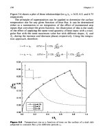
2.7.2
Extension to Multilayered Semi-Infinite Solid
The single-layer approach is not adequate for modeling diamond coating on
substrates such as steel, where a buffer layer would be necessary to prevent
the formation
of
graphite at the diamond/steel interface. An approximate
method is presented here to extend the single layer to two layers without
repeating the extensive finite difference modeling and is intended for use as a
design approximation. Figure 12.5 illustrates the model for the two-layer
coating case.
The following
tional convenience:
dimensionless relations were developed for computa-
e,,
=
T,,
(Z)
-
=
e
s
-
e
ss0
(12.1)
(1
2.2)
where
e,,
=
the dimensionaless maximum temperature rise in the solid surface
Ts,
relative
to
the maximum unlayered surface temperature rise
T,
e,,
=
the dimensionless maximum temperature rise in the surface layer
T,
relative to the maximum unlayered surface temperature rise
T,
6,
=
the maximum unlayered surface temperature rise
Ts
OS,
=
the dimensionless maximum temperature rise in the solid surface
0,
=
the dimensionless maximum temperature rise in the surface layer
Kd
=
thermal conductivity of diamond
Procedure to Predict Multilayer Temperature Rise
A numerical example illustrates the simplified procedure used to predict
maximum temperature rise in a multilayered solid. The procedure involves
the following steps:
For a given velocity,
U,
and length
of
contact,
I,
calculate the
dimensionless temperature rise,
Oo4
and
tITojf,
for the case of a
1.
Surface
Coating
477
9t
T
i
U-
Figure
1
2.5
Two-layered semi-infinite solid moving
source with a Hertzian distribution.
under a stationary
heat
2.
3.
4.
diamond layer on the buffer layer substrate using
Eqs
(1
2.1) and
(12.2). The values for the surface layer thickness,
hd,
should vary
from
0
to a specified upper limit (0.016mm was used in this
study).
The ratio between the surface layer and buffer layer maximum
temperature rise is
now
determined. The ratio will remain con-
stant, although the temperature values will be adjusted up or
down based on the uncoated steel temperature.
For the same
U
and
I,
calculate the dimensionless temperature
rise,
Ood
and
Ososs,
for the case
of
a buffer layer on the steel
substrate using
Eqs
(12.1)
and (2.2). For simplicity, the same
values for
hf
are used for
hd
in step
1
above (see Fig. 12.6).
The maximum dimensionless temperature rise in the buffer layer,
Og,
in the steel substrate,
OS,,
and in the diamond layer,
Od
can
4
78
Chapter
12
14
1
n
-
-
I
I
I
I
I
I
1
U
0
2
4 6
8
10
12
14 16
h,,,
x
10'
Figure
12.6
Dimensionless temperature rise (prior
to
data manipulation) in sub-
strate surface and coating layer surface for diamond on
AISI
304
stainless steel with
a silicon nitride interface layer.
(U
=
12.7 m/sec,
I
=
0.25
mm.)
now be determined. First, the steel substrate temperature rise
is
scaled by the ratio of the buffer layer temperatures (see Eq.
(12.3)).
A
scaling factor,
A,
is then determined in Eq. (1.24).
This factor scales the diamond layer, buffer layer and steel sub-
strate temperatures to the uncoated steel substrate temperature,
Osss.
This factor insures that the temperature rise predictions all
start at the uncoated steel substrate temperature at
hd
=
hf
=
0,
and then decrease or increase as the coating thicknesses increase.
Equation (12.5) shows how
A
is
used to calculate the dimension-
less temperature rise for the diamond and buffer layers
(6,
and
Of)
and the steel substrate
(6.T.y)
(see Fig. 12.7).
The actual temperature rise
(Ty.y,
Tf, Td)
can now be calculated
by
Eq.
(12.6). Figure 12.8 shows a typical result for
qr
=
1000
W/
mm
.
5.
2
Surface
Coating
479
3.5
I
E
f
(D
2.5
2.0
F
2
1.5
aa
-
5
'i
1.0
r
Q)
0.5
0.0
0
2
4
6
8
10
12
14
16
h,
x
30'
Figure
1
2.7
Dimensionless temperature rise (following data manipulation) in
substrate surface and coating layer surface for diamond on
AISI
304
stainless steel
with a silicon nitride interface layer.
(U
=
12.7m/sec,
I
=
0.25mm.)
For
i
=
1
to
n:
eLSS
%
A=
For
i
=
1
to
n:
(1
2.3)
(1
2.4)
41
T=8-
Kd
(I
2.5)
(1
2.6)
