Fundamentals of Structural Analysis Episode 1 Part 5 pps
Bạn đang xem bản rút gọn của tài liệu. Xem và tải ngay bản đầy đủ của tài liệu tại đây (184.52 KB, 20 trang )
Truss Analysis: Force Method, Part II by S.T.Mau
75
Work done by external force (left) and work done by interanl force (right)-case 1.
The conservation of mechanical energy principle calls for
2
1
∑
=
n
i
i
1
P
∆
i
=
2
1
j
M
j
j
VF
∑
=1
(15)
(2) The case of virtual unit load acts alone. The figure below illustrates the force-
displacement histories.
Work done by external force (left) and work done by interanl force (right)-case 2.
Again, the energy conservation principle calls for
2
1
(1)
∆
o
'
=
2
1
j
M
j
j
vf
∑
=1
(16)
(3) The case of the virtual unit load being applied first, followed by the application of the
real loads. The force-displacement histories are shown in the figures below.
∆
i
P
i
D
isp.
E
xternal Force
V
j
E
long.
I
nternal Force
F
j
∆
o
'
1
D
isp.
E
xternal Force
v
j
E
long.
I
nternal Force
f
j
Truss Analysis: Force Method, Part II by S.T.Mau
76
Work done by external forces (left) and work done by interanl forces (right)-case 3.
Application of the energy conservation principle leads to
2
1
(1)
∆
o
'
+
2
1
∑
=
n
i
i
1
P
∆
i
+ (1) (
∆
o
) =
2
1
j
M
j
j
vf
∑
=1
+
2
1
j
M
j
j
VF
∑
=1
+
j
M
j
j
Vf
∑
=1
(17)
Substracting Eq. 17 by Eq. 15 and Eq. 16 yields
(1) (
∆
o
) =
j
M
j
j
Vf
∑
=1
(14)
which is the principle of virtual force statement expresssed in the unit-load context.
Example 15. Find the vertical displacement at node 2 of the truss shown, given E=10
GPa, A=100 cm
2
for all bars.
1
D
isp.
E
xternal Force
E
long.
I
nternal Force
∆
o
'
∆
o
v
j
f
j
V
j
∆
i
P
i
D
isp.
E
xternal Force
F
j
Truss Analysis: Force Method, Part II by S.T.Mau
77
Example to find a nodal displacement by the unit load method.
Solution. Using the unit load method requires the solution for the member elongation, V
i
,
under the appied load and the virtual member force, f
i
, under the unit load as shown in the
figure below.
A unit load applied in the direction of the displacement to be solved.
The computation in Eq. 14 is carried out in a table as shown, keeping in mind that the
virtual member forces are associated with the virtual unit load and the nodal displacement
is associated with the member elongation as indicated below.
1 (
∆
) = Σ f
i
(V
ι
)
Since both the real loading problem and the virtual unit load problem have been solved in
earlier examples, we shall not go through the process again except to note that in order to
find member elongation V
ι
, we must find member force F
ι
first. The sequence of
computation is implied in the layout of the table below.
∆
1
2
4m
3
12
3
1.0 kN
0.5 kN
1
2
4m
3m
3
3m
12
3
1 kN
3m
3m
Truss Analysis: Force Method, Part II by S.T.Mau
78
Computing the Vertical Displacement at Node 2
Real Load Unit Load Cross-term
F EA/L V
i
f
i
f
i
V
i
Member
(kN) (kN/m) (mm) kN (kN-mm)
1 -0.20 20,000 -0.011 -0.625 0.0069
2 -1.04 20,000 -0.052 -0.625 0.0325
3 0.62 16,700 0.037 0.375 0.0139
Σ
0.0533
Thus, the vertical displacement at node 2 is 0.0533 mm, downward.
Example 16. Find (a)the relative movement of nodes 2 and 6 in the direction joining
them and (b) rotation of bar 2, given E=10 GPa, A=100 cm
2
for all bars.
Example on finding relative displacements.
Solution. The nodal displacments related to the relative movement and rotation in
question are depicted in the figures below.
Relavant nodal displacements.
To find the relative movement between node 2 and node 6, we can apply a pair of unit
loads as shown. We shall call this case as case (a).
1
2
3
4
5
6
1
2
3
4
5
6
7
8
9
120 kN
4m
3@4m=12m
2
120 kN
6
∆
2
∆
6
2
120 kN
6
∆
2
∆
3
Truss Analysis: Force Method, Part II by S.T.Mau
79
Unit load for movement between node 2 and node 6 in the direction of 2-6, case (a).
To find the rotation of bar 2, we can apply a pair of unit loads as shown. We shall call
this case as case (b).
Unit load to find rotation of bar 2, case (b).
The computation entails the following:
(1) Find member forces, F
i
, corresponding to the real applied load.
(2) Compute member elongation, V
i
.
(3) Find member force, f
ia
, cooresponding to the case (a) load.
(4) Find member force, f
ib
, cooresponding to the case (b) load.
(5) Apply Eq. 13 to find the displacement quantities.
(6) Make necessary adjustments to put member rotation in the right unit.
Steps (1) to (5) are summarized in the following table.
2
6
1 kN
1 kN
6
2
1 kN 1 kN
Truss Analysis: Force Method, Part II by S.T.Mau
80
Computing for Relative Displacement Quantities
Real Load Unit Load Cross-term
F EA/L V
i
f
ia
f
ib
f
ia
V
i
f
ib
V
i
Member
(kN) (kN/m) (mm) (kN) (kN) (kN-mm) (kN-mm)
1 80.00 25,000 3.20 0.00 -0.33 0.00 -1.06
2 80.00 25,000 3.20 -0.71 -0.33 -2.26 -1.06
3 40.00 25,000 1.60 0.00 0.33 0.00 0.53
4
-113.13 17,680 -6.40 0.00 0.47 0.00 -3.00
5
120.00 25,000 4.80 -0.71 -1.00 -3.40 -4.80
6
-56.56 17,680 -3.20 1.00 0.94 -3.20 -3.00
7
40.00 25,000 1.60 -0.71 0.33 -1.14 0.53
8
-56.56 17,680 -3.20 0.00 -0.47 0.00 1.50
9
-40.00 25,000 -1.60 -0.71 -0.33 1.14 0.53
Σ
-8.86 -9.83
For case (a), Eq. 14 becomes
(1) (
∆
2
+
∆
6
) =
j
M
j
j
Vf
∑
=1
= -8.86 mm.
The relative movement in the direction of 2-6 is 8.86 mm in the opposite direction of
what was assumed for the unit load, i.e., away from each other, not toward each other.
For case (b), Eq. 14 becomes
(1) (
∆
2
+
∆
3
) =
j
M
j
j
Vf
∑
=1
= -9.83 mm.
For the rotation of bar 2, we note that the –9.83 computed represents a relative vertical
movement between node 2 and node 3 of 9.83 mm in the opposite direction of what was
assumed for the pair of unit loads. That relative vertial movement translates into a
counterclockwise rotation of 9.83mm/4,000mm=0.0025 radian.
9.83 mm
4 m
Truss Analysis: Force Method, Part II by S.T.Mau
81
Problem 5.
(1) Find the horizontal displacement of node 2 of the loaded truss shown, given E=10
GPa, A=100 cm
2
for all bars.
Problem 5-1.
(2) Find the horizontal displacement of node 2 of the loaded truss shown, given E=10
GPa, A=100 cm
2
for all bars. The magnitude of the pair of loads is 141.4 kN.
Problem 5-2.
(3) The lower chord members 1, 2, and 3 of the truss shown are having a 20
o
C increase in
temperature. Find the horizontal displacement of node 5, given E=10 GPa, A=100
cm
2
for all bars and the linear thermal expansion coefficient is
α
=5(10
-6
)/
o
C.
Problem 5-3.
1
2
4m
3m
3
3m
1
2
3
1.0 kN
0.5 kN
1
2
3
4
5
6
1
2
3
4
5
6
7
8
9
4m
3@4m=12m
1
2
3
4
5
6
1
2
3
4
5
6
7
8
9
4m
3@4m=12m
Truss Analysis: Force Method, Part II by S.T.Mau
82
6. Indeterminate Truss Problems – Method of Consistent
Deformations
The truss shown below has 15 members (M=15) and four reaction forces(R=4). The total
number of force unknowns is 19. There are nine nodes (N=9). Thus, M+R-2N=1. The
problem is statically indeterminate to the first degree. In addition to the 18 equlibrium
equations we can establish from the nine nodes, we need to find one more equation in
order to solve for the 19 unknowns. This additional equation can be established by
considering the consistency of deformations (deflections) in relation to geometrical
constraints.
Statically indeterminate truss with one degree of redundancy.
We notice that if the vertical reaction at the central support is known, then the number of
force unknowns becomes 18 and the problem can be solved by the 18 equalibrium
equation from the nine nodes. The key to solution is then to find the central support
reaction, which is called the redundant force. Denoting the vertical reaction of the central
support by R
c
, the original problem is equivalent to the problem shown below as far as
force equlibrium is concerned.
Statically equilvalent problem with the redundant force R
c
as unknown.
The truss shown above, with the central support removed, is called the “primary
structure.” Note that the primary structure is statically determinate. The magnitude of R
c
is determined by the condition that the vertical displacement of node c of the primary
structure due to (1) the applied load P and (2) the redundan force R
c
is zero. This
condition is consistent with the geometric constraint imposed by the central support on
the original structure. The vertical displacement at node c due to the applied load P can
be determined by solving the problem associated with the primary structure as shown
below.
P
P
R
c
c
Truss Analysis: Force Method, Part II by S.T.Mau
83
Displacement of node c of the primary structure due to the applied load.
The displacement of node c due to the redundant force R
c
cannot be computed directly
because R
c
itself is unknown. We can compute, however, the displacement of node c of
the primary structure due to a unit load in the direction of R
c
as shown. This
displacement is denoted by
δ
cc
, the double subscript ‘cc’ signified displacent at ‘c’ (first
subscript) due to a unit load at ‘c’ (second subscript).
Displacement at c due to a unit load at c.
The vertical dispalcement at c due to the redundant force R
c
is then R
c
δ
cc
, as shown in the
figure below.
Displacement at c due to the redundant force R
c
.
The condition that the total vertical displacement at node c,
∆
c
, be zero is expressed as
∆
c
=
∆
’
c
+ R
c
δ
cc
= 0 (18)
This is the additional equation needed to solve for the redundant force R
c
. Once R
c
is
obtained, the rest of the force unknowns can be computed from the regular joint
equilibrium equations. Eq. 18 is called the condition of compatibility.
c
c
R
c
R
c
δ
cc
P
∆
’
c
c
1 kN
δ
cc
Truss Analysis: Force Method, Part II by S.T.Mau
84
We may summarize the concept behind the above procedures by pointing out that the
original problem is solved by replacing the indeterminate truss with a determinate
primary structure and superposing the solutions of two problems, each determinate, as
shown below.
The superposition of two solutions.
And, the key equation is the condition that the total vertical displacement at node c must
be zero, consisdent with the support condition at node c in the original problem. This
method of analysis for statically indeterminate structures is called the method of
consistent deformations.
Example 17. Find the force in bar 6 of the truss shown, given E=10 GPa, A=100 cm
2
for
all bars.
Example of an indeterminate truss with one redundant.
1 kN
0.5 kN
1
4
3
2
4 m
3 m
1
2
3
4
56
c
P
∆
’
c
c
R
c
R
c
δ
cc
+
Truss Analysis: Force Method, Part II by S.T.Mau
85
Solution. The primary structure is obtained by introducing a cut at bar 6 as shown in the
left figure below. The original problem is replaced by that of the left figure and that of
the middle figure. The condition of compatibility in this case requires that the total
relative displacement across the cut obtained from the superpostion of the two solutions
be zero.
∆
=
∆
’ + F
6
δ = 0
Superposition of two solutions.
where
∆
’ is the overlap length (opposite of a gap) at the cut due to the applied load and
δ
is, as defined in the figure below, the overlap length across the cut due to a pair of unit
loads applied at the cut.
Overlap displacement at the cut due to the unit-force pair.
The computation needed to find
∆
’ and
δ
is tabulated below.
1 kN
1
4
3
2
1
2
3
4
5
14
3
2
1
2
3
4
5
1
14
3
2
1
2
3
4
5
F
6
δ
F
6
δ
∆
’
1 kN
0.5 kN
1
4
3
2
1
2
3
4
5
6
0.5 kN
+
=
1
Truss Analysis: Force Method, Part II by S.T.Mau
86
Computing for
∆
’ and
δ
Real Load
For
∆
’ For
δ
F
i
EA /L
V
ι
f
i
f
i
V
ι
v
i
f
i
v
i
Member
(kN) (kN/m) (mm) (kN/kN) (mm) (mm/kN) (mm/kN)
1 -0.33 25,000 -0.013 -0.8 0.010 -0.032 0.026
2 0 33,333 0 -0.6 0 -0.018 0.011
3 0 25,000 0 -0.8 0 -0.032 0.026
4 0.50 33,333 0.015 -0.6 -0.009 -0.018 0.011
5 -0.83 20,000 -0.042 1.0 -0.042 0.050 0.050
6 0 20,000 0 1.0 0 0.050 0.050
Σ
-0.040 0.174
Note: F
i
= ith member force due to the real applied load.
V
ι
= F
i
/ (EA/L)
i
=ith member elongation due to the real applied load.
f
i
= ith member force due to the virtual unit load pair at the cut.
v
i
= f
i
/ (EA/L)
i
is the ith member elongation due to the virtual unit load
pair at the cut.
∆
’= -0.040 mm,
δ
= 0.174 mm/kN
From the condition of compatibility:
∆
’ + F
6
δ
= 0 F
6
= −
174.0
040.0
−
= 0.23 kN.
Example 18. Formulate the conditions of compatibility for the truss problem shown.
Statically indeterminate truss with two degrees of redundancy.
Solution. The primary structure can be obtained by removing the supports at node c and
node d. Denoting the reaction at node c and node d as R
c
and R
d
, respectively, the original
P
c
d
Truss Analysis: Force Method, Part II by S.T.Mau
87
problem is equivalent to the superpostion of the three problems as shown in the figure
below.
Superposition of three determinate problems.
In the above figure.
∆
’
c
: vertical displacement at node c due to the real applied load,
∆
’
d
: vertical displacement at node d due to the real applied load,
δ
cc
: vertical displacement at node c due to a unit load at c,
δ
cd
: vertical displacement at node c due to a unit load at d,
δ
dc
: vertical displacement at node d due to a unit load at c, and
δ
dd
: vertical displacement at node d due to a unit load at d.
The conditions of compatibility are the vertical displacements at nodes c and d be zero:
∆
c
=
∆
’
c
+ R
c
δ
cc
+ R
d
δ
cd
= 0
(19)
∆
d
=
∆
’
d
+ R
c
δ
dc
+ R
d
δ
dd
= 0
c
P
∆
’
c
c
R
c
R
c
δ
cc
c
R
d
R
d
δ
cd
d
∆
’
d
R
c
δ
dc
d
d
R
d
δ
dd
+
+
Truss Analysis: Force Method, Part II by S.T.Mau
88
The above equations can be solved for the two redundant forces R
c
and R
d.
Denote
V
i
: the ith member elongation due to the real applied load,
f
ic
: the ith member force due to the unit load at c.
v
ic
: the ith member elongation due to the unit load at c.
f
id
: the ith member force due to the unit load at d, and
v
id
: the ith member elongation due to the unit load at d,
we can express the displacements according to the unit load method as
∆
’
c
= Σ f
ic
(V
ι
)
∆
’
d
= Σ f
id
(V
ι
)
δ
cc
= Σ f
ic
(v
ι
c
)
δ
dc
= Σ f
ic
(v
ι
d
)
δ
cd
= Σ f
id
(v
ι
c
)
δ
dd
= Σ f
id
(v
ι
d
)
The member elongation quantities in the above equations are related to the member
forces through
V
ι
=
ii
ii
AE
LF
v
ι
c
=
ii
iic
AE
Lf
v
ι
d
=
ii
iid
AE
Lf
Thus, we need to find only member forces F
i
, f
ic
, and f
id
, corresponding to the real load, a
unit load at node c and a unit load at node d , respectively, from the primary structure.
7. Laws of Reciprocity
In the last example we came across
δ
cd
and
δ
dc
, which can be expressed
in terms of
member forces:
Truss Analysis: Force Method, Part II by S.T.Mau
89
δ
cd
= Σ f
id
(v
ι
c
) = Σ f
id
(
ii
iic
AE
Lf
)
δ
dc
= Σ f
ic
(v
ι
d
) = Σ f
ic
(
ii
iid
AE
Lf
)
Comparing the two equations we conclude that
δ
cd
=
δ
dc
(20)
Eq. 20 states “ displacement at point c due to a unit load at point d is equal to the
displacement at d due to a unit load at point c.” Here all displacements and unit loads are
in the vertical direction, but the above statement is also true even if the displacements and
unit loads are in different directions as long as there is a cross-correspondence as shown
in the following figures.
Reciprocal displacements.
Eq. 20 is called the Maxwell’s Law of Reciprocal Displacements. As a result of
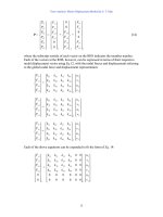
Maxwell’s law, the equations of compatibility, Eq. 19, when put into a matrix form, will
always have a symmetrical matrix because
δ
cd
is equal to
δ
dc
.
⎥
⎦
⎤
⎢
⎣
⎡
dddc
cdcc
δδ
δδ
⎭
⎬
⎫
⎩
⎨
⎧
d
c
R
R
=
⎭
⎬
⎫
⎩
⎨
⎧
−
−
d
c
'
'
∆
∆
(21)
Consider now two systems, system A and system B, each derived from the above two
figures by replacing the unit load by a load of magnitude P and Q, respectively. Then the
c
1
c
1
δ
cd
δ
dc
d
d
Truss Analysis: Force Method, Part II by S.T.Mau
90
magnitude of displacements will be proportionally adjusted to what are shown in the
figure below.
Two loading and displacement systems.
We state “ the work done by the load in system A upon the displacement of system B is
equal to the work done by the load in system B upon the displacement in system A.” This
statement is true because
P (Q
δ
cd
) = Q (P
δ
dc
)
according to the Maxwell’s law of reciprocal displacement. This statement can be further
generalized to include multiple loads: “the work done by the loads in system A upon the
displacements of system B is equal to the work done by the loads in system B upon the
displacements in system A.” This statement is called Betti’s Law of Reciprocity. It is the
generalization of the Maxwell’s reciprocal law. Both are applicable to linear, elastic
structures.
8. Concluding Remarks
The force method is easy to apply with hand calculation for statically deteminate
problems or indeterminate problem with one or two redundants. For three or more
redundants, a systematic approach using a matrix formulation can be developed. Such a
matrix force method formulation is of theoretical interest and its practical application is
not as common as that of the matrix displacement method. Details of the matrix force
method can be found in textbooks such as Elementary Theory of Structures, by Yaun-Yu
Hsieh and S. T. Mau, 4
th
edition, Prentice Hall, 1995, and Matrix Structural Analysis, by
William McGuire and Richard H. Gallagher, John Wiley and Sons, 1979.
c
P
c
Q
Q
δ
cd
P
δ
dc
d
d
System A
System B
Truss Analysis: Force Method, Part II by S.T.Mau
91
Problem 6.
(1) Find the force in member 10 of the loaded truss shown, given E=10 GPa, A=100 cm
2
for all bars.
Problem 6-1.
(2) Find the force in bar 6 of the truss shown, given E=10 GPa, A=100 cm
2
for all bars.
Problem 6-2.
1
2
3
4
5
6
1 2
3
4
5
6
7
8
9
4m
3@4m=12m
10
120 kN
10 kN
1
4
3
2
4 m
3 m
1
2
3
4
5
6
Truss Analysis: Force Method, Part II by S.T.Mau
92
93
Beam and Frame Analysis: Force Method, Part I
1. What Are Beams and Frames?
The figure below illustrates the various components in a plane frame system. Each
of these components can take loads acting in any direction at any point along its
length. A frame is consisted of beams and columns. In a gravity field, the vertical
components are called columns and the horizontal components beams. Since the
gravity load is usually the predominant load, we expect that the columns will carry
mostly axial load and the beams transverse load, even though both can take axial and
transverse loads.
A plane frame system
As shown above, a frame can be supported by hinge or roller supports as a truss can but it
can also be supported by a so-called clamped or fixed support which prevents not only
translational motions but also rotational motion at a section. As a result, a fixed support
provides three reactions, two forces and a moment. The frame we refer to herein is called
a rigid frame which means the connection between its components are rigid connections
that do not allow any translational and rotational movement across the connection. In the
above figure, since it is a rigid frame, all angles at the beam-column junction will remain
at 90-degrees before or after any deformations. For other rigid frame systems, the angles
at connections between all components will remain at the same angle before or after
deformations.
Let us examine an element of a beam or column and show all the internal as well as
external forces acting on the element.
Overhang
Cantilever
B
eam
Column
Clamped (Fixed)
Support
R
oller Support
H
inge Support
Beam and Frame Analysis: Force Method, Part I by S. T. Mau
94
Beam or column element with internal and external forces.
As we can see, at a typical section there are three possible actions or internal forces,
bending moment, M, shear force, V, and axial force or thrust, T. For a beam, the
dominant internal forces are bending moments and shear forces; for a column, the axial
force dominates. In any case, the internal actions are much more complicated than those
of a truss member, which has only a constant axial force.
2. Statical Determinacy and Kinematic Stability
Instability due to improper support. A beam or frame is kinematically unstable if the
support conditions are such that the whole structure is allowed to move as a mechanism.
Examples of improper support and insufficient support are shown below.
Improper or insufficient support conditions.
Instability due to improper connection. A beam or frame is kinematically unstable if
the internal connection conditions are such that part of or the whole structure is allowed
to move as a mechanism. Examples of improper connections are shown below.
M
V
T
T
V
M