Fundamentals of Structural Analysis Episode 1 Part 6 doc
Bạn đang xem bản rút gọn của tài liệu. Xem và tải ngay bản đầy đủ của tài liệu tại đây (192.01 KB, 20 trang )
Beam and Frame Analysis: Force Method, Part I by S. T. Mau
95
Improper internal connections.
Statical determinacy. A stable beam or frame is statically indeterminate if the number
of force unknowns is greater than the number of equilibrium equations. The difference
between the two numbers is the degree of indeterminacy. The number of force unknowns
is the sum of the number of reaction forces and the number of internal member force
unknowns. For reaction forces, a roller has one reaction, a hinge has two reactions and a
clamp has three reactions as shown below.
Reaction forces for different supports.
To count internal member force unknowns, first we need to count how many members
are in a frame. A frame member is defined by two end nodes. At any section of a member
there are three internal unknown forces, T , V, and M. The state of force in the member is
completely defined by the six nodal forces, three at each end node, because the three
internal forces at any section can be determined from the three equilibrium equations
taken from a FBD cutting through the section as shown below, if the nodal forces are
known.
Internal section forces are functions of the nodal forces of a member.
Thus, each member has six nodal forces as unknowns. Denoting the number of members
by M and the number of reaction forces at each support as R, the total number of force
unknowns in a frame is then 6M+ΣR.
x
T
V
M
Beam and Frame Analysis: Force Method, Part I by S. T. Mau
96
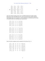
On the other hand, each member generates three equilibrium equations and each node
also generates three equilibrium equations. Denoting the number o f nodes by N, The
total number of equilibrium equations is 3M+3N.
FBDs of a node and two members.
Because the number of members, M, appears both in the count for unknowns and the
count for equations, we can simplify the expression for counting unknowns as shown
below.
Counting unknowns against available equations.
The above is equivalent to considering each member having only three force unknowns.
The other three nodal forces can be computed using these three nodal forces and the three
member equilibrium equations. Thus, a frame is statically determinate if 3M+ΣR= 3N.
If one or more hinges are present in a frame, we need to consider the conditions
generated by the hinge presence. As shown in the following figure, the presence of a
hinge within a member introduces one more equation, which can be called the condition
of construction. A hinge at the junction of three members introduces two conditions of
construction. The other moment at a hinge is automatically zero because the sum of all
moments at the hinge (or any other point) must be zero. We generalize to state that the
conditions of construction, C, is equal to the number of joining members at a hinge, m,
minus one, C=m-1. The conditions of construction at more than one hinges is ΣC.
Nodal
E
q
uilibrium
Member
E
q
uilibrium
Member
E
q
uilibrium
N
umber of unknowns=6M+ΣR
N
umber of equations= 3M+3
N
N
umber of unknowns=3M+ΣR
N
umber of equations= 3N
Beam and Frame Analysis: Force Method, Part I by S. T. Mau
97
Since the conditions of construction provide additional equations, the available equation
becomes 3N+C. Thus, in the presence of one or more internal hinges, a frame is statically
determinate if 3M+ΣR= 3N+ΣC.
Presence of hinge introduces additional equations.
Example 1. Discuss the determinacy of the beams and frames shown.
Solution. The computation is shown with the figures.
M
T
V
M
=0
T
V
M
T
V
M
T
V
M
T
V
M
T
V
M
=0
T
V
M
=0
T
V
M
T
V
M
T
V
=0
=0
Beam and Frame Analysis: Force Method, Part I by S. T. Mau
98
Counting internal force unknowns, reactions, and available equations.
For frames with many stories and bays, a simpler way of counting of unknowns and
equations can be developed by cutting through members to produce separate “trees” of
frames, each is stable and determinate. The number of unknowns at the cuts is the
number of degree of indeterminacy as shown in the example that follows.
Example 2. Discuss the determinacy of the frame shown.
R
=3
R
=2
N
umber of unknowns = 3M+ΣR =7,
N
umber of equations = 3N+ΣC = 7
Staticall
y
determinate.
R
=1
R
=3
N
umber of unknowns 3M+ΣR =15,
N
umber of equations = 3N+C = 13
I
ndeterminate to the 2
nd
degree.
N
umber of unknowns = 3M+ΣR =21,
N
umber of equations = 3N+C = 20
I
ndeterminate to the 1
st
degree.
R
=3
R
=3
R
=2
R
=1
R
=3
R
=1
N
umber of unknowns = 3M+ΣR =10,
N
umber of equations = 3N+C= 10
Statically determinate.
N
umber of unknowns = 3M+ΣR =12,
N
umber of equations = 3N+ΣC= 11
I
ndeterminate to the 1
st
degree.
R
=1
R
=3
R
=2
M
=1, N=2, C=0
M
=1, N=2, C=1
M
=3, N=4, C=1
M
=5, N=6, C=2
M
=2, N=3, C=1
M
=2, N=3, C=2
R
=3
N
umber of unknowns = 3M+ΣR =8,
N
umber of equations = 3N+ΣC = 6
I
ndeterminate to the 2
nd
de
g
ree.
Beam and Frame Analysis: Force Method, Part I by S. T. Mau
99
Multi-story multi-bay indeterminate frame.
We make nine cuts that separate the original frame into four “trees” of frames as shown.
Nine cuts pointing to 27 degrees of indeterminacy.
We can verify easily that each of the stand-alone trees is stable and statically determinate,
i.e. the number of unknowns is equal to the number of equations in each of the tree
problems. At each of the nine cuts, three internal forces are present before the cut. All
together we have removed 27 internal forces in order to have equal numbers of unknowns
and equations. If we put back the cuts, we introduce 27 more unknowns, which is the
degrees of indeterminacy of the original uncut frame.
This simple way of counting can be extended to multi-story multi-bay frames with
hinges: simply treat the conditions of construction of each hinge as “releases” and
subtract the ∑C number from the degrees of indeterminacy of the frame with the hinges
removed. For supports other than fixed, we can replace them with fixed supports and
counting the “releases” for subtracting from the degrees of indeterminacy.
Example 3. Discuss the determinacy of the frame shown.
Indeterminate frame example.
1
2
3
4
5
6
7
8
9
Beam and Frame Analysis: Force Method, Part I by S. T. Mau
100
Solution. Two cuts and five releases amounts to 2x3-5=1. The frame is indeterminate to
the first degree.
Short cut to count degrees of indeterminacy.
1
2
C=1
C=2
C=2
Beam and Frame Analysis: Force Method, Part I by S. T. Mau
101
Problem 1. Discuss the determinacy of the beams and frames shown.
(1) (2)
(3) (4)
(5) (6)
(7) (8)
Problem 1.
Beam and Frame Analysis: Force Method, Part I by S. T. Mau
102
3. Shear and Moment Diagrams
A beam is supported on a roller and a hinge and is taking a concentrated load, a
concentrated moment and distributed loads as shown below.
A loaded beam and the FBD of a typical infinitesimal element.
A typical element of width dx is isolated as a FBD and the forces acting on the FBD are
shown. All quantities shown are depicted in their positive direction. It is important to
remember that the positive direction for T, V, and M depends on which face they are
acting on. It is necessary to remember the following figures for the sign convention for T,
V, and M.
Positive directions for T, V, and M.
We can establish three independent equilibrium equations from the FBD.
Σ F
x
=0 −T+F+(T+dT)=0 dT=−F
Σ F
y
=0 V−P−qdx− (V+dV)=0 dV= −P−qdx
Σ M
c
=0 M+M
o
− (M+dM)+Vdx=0 dM= M
o
+Vdx
x
dx
T+dT
V+dV
M
+dM
q
F
P
M
o
dx
M
T
V
C
T
V
M
Beam and Frame Analysis: Force Method, Part I by S. T. Mau
103
The first equation deals with the equilibrium of all forces acting in the axial direction. It
states that the increment of axial force, dT, is equal to the externally applied axial force,
F. If a distributed force is acting in the axial direction, then F would be replaced by fdx,
where f is the intensity of the axially distributed force per unit length. For a beam, even if
axial forces are present, we can consider the axial forces and their effects on
deformations separately from those of the transverse forces. We shall now concentrate
only on shear and moment.
The second and the third equations lead to the following differential and integral relations
dx
dV
= −q(x), V=
∫
− qdx
for distributed loads (1)
∆
V= −P for concentrated loads (1a)
dx
dM
= V, M=
∫
Vdx
(2)
∆
M= M
o
for concentrated moments (2a)
Note that we have replaced the differential operator d with the symbol
∆
in Eq. 1a and
Eq. 2a to signify the fact that there will be a sudden change across a section when there is
a concentrated load or a concentrated moment externally applied at the location of the
section.
Differentiating Eq. 2 once and eliminating V using Eq. 1, we arrive at
2
2
dx
Md
= −qM=−
dxqdx
∫∫
(3)
The above equations reveal the following important features of shear and moment
variation along the length of a beam.
(1) The shear and moment change along the length of the beam as a function of x. The
shear and moment functions, V(x) and M(x), are called shear and moment diagrams,
respectively, when plotted against x.
(2) According to Eq. 1, the slope of the shear diagram is equal to the negative value of
the intensity of the distributed load, and the integration of the negative load intensity
function gives the shear diagram.
(3) According to Eq. 1a, wherever there is a concentrated load, the shear value changes
by an amount equal to the negative value of the load.
(4) According to Eq. 2, the slope of the moment diagram is equal to the value of the
shear, and the integration of the shear function gives the moment diagram.
Beam and Frame Analysis: Force Method, Part I by S. T. Mau
104
(5) According to Eq. 2a, wherever there is a concentrated moment, the moment value
changes by an amount equal to the value of the concentrated moment.
(6) According to Eq. 3, the moment function and load intensity are related by twice
differentiation/integration.
Furthermore, integrating once from Eq. 1 and Eq. 2 leads to
V
b
= V
a
+
∫
−
b
a
qdx
(4)
and
M
b
= M
a
+
∫
b
a
Vdx
(5)
where a and b are two points on a beam.
Equations 4 and 5 reveal practical guides to drawing the shear and moment diagrams:
(1) When drawing a shear diagram starting from the leftmost point on a beam, the shear
diagram between any two points is flat if there is no loads applied between the two points
(q=0). If there is an applied load (q≠0), the direction of change of the shear diagram
follows the direction of the load and the rate of change is equal to the intensity of the
load. If a concentrated load is encountered, the shear diagram, going from left to right,
moves up or down by the amount of the concentrated load in the direction of the load
(Eq. 1a). These practical rules are illustrated in the figure below.
Shear diagram rules for different loads.
(2) When drawing a moment diagram starting from the leftmost point on a beam, the
moment diagram between any two points is (a) linear if the shear is constant, (b)
parabolic if the shear is linear, etc. The moment diagram has a zero slope at the point
where shear is zero. If a concentrated moment is encountered, the moment diagram,
going from left to right, moves up/down by the amount of the concentrated moment if the
moment is counterclockwise/clockwise (Eq. 2a). These practical rules are illustrated in
the figure below.
ab
ab
V
V
b
V
a
a
b
a
b
V
V
b
V
a
q
q
1
ab
V
V
b
V
a
P
a
b
P
Beam and Frame Analysis: Force Method, Part I by S. T. Mau
105
Moment diagram rules for different shear diagrams and loads.
Example 4. Draw the shear and moment diagrams of the loaded beam shown.
Example for shear and moment diagrams of a beam.
Solution. We shall give a detailed step-by step solution.
(1) Find reactions. The first step in shear and moment diagram construction is to find the
reactions. Readers are encouraged to verify the reaction values shown in the figure
below, which is the FBD of the beam with all the forces shown.
FBD of the beam showing applied and reaction forces.
(2) Draw the shear diagram from left to right.
3 kN/m
2m 3m
3m
6 kN
3 kN/m
2m 3m
3m
6 kN
10 kN
2 kN
ab
V
ab
M
ab
M
M
o
a
b
a
b
M
M
b
M
a
V
a
1
V
a
a
b
V
M
o
Beam and Frame Analysis: Force Method, Part I by S. T. Mau
106
Drawing the shear diagram from left to right.
(3) Draw the moment diagram from left to right.
Drawing the moment diagram from left to right.
-6 kN-m
V
P
arabolic
L
inear
-6 kN
M
V
-6 kN
4 kN
F
lat
V
-6 kN
-2 kN
F
lat
1m
3 kN
2m
10 kN
4 kN
6 kN
-6 kN-m
L
inear
6 kN-m
M
-6 kN-m
6 kN-m
M
L
inear
1m
4 kN
2m
Beam and Frame Analysis: Force Method, Part I by S. T. Mau
107
Example 5. Draw the shear and moment diagrams of the loaded beam shown.
Example for shear and moment diagrams of a beam.
Solution. We shall draw the shear and moment diagrams directly.
(1) Find reactions.
FBD showing all forces.
(2) Draw the shear diagram from left to right.
Drawing shear diagram from left to right.
3 kN/m
2m 6m
6 kN
2m
6 kN
3 kN/m
2m 3m
3m
6 kN
2m
6 kN
15 kN
15 kN
3 kN/m
2m
3m
3m
6 kN
2m
6 kN
15 kN
15 kN
6 kN
-6 kN
9 kN
-9 kN
V
V
Beam and Frame Analysis: Force Method, Part I by S. T. Mau
108
(3) Draw the moment diagram from left to right.
Drawing moment diagram from left to right.
Example 6. Draw the shear and moment diagrams of the loaded beam shown.
Example for shear and moment diagrams of a beam.
Solution.
(1) Find reactions.
FBD showing all forces.
(2) Draw the shear diagram from left to right.
2m 3m
3m
2m
15 kN
13.5 kN-m
M
-6 kN/m
6 kN/m
1.5 kN
M
-12 kN/m
-12 kN/m
30 kN-m
2m
6 kN
2m
6 kN
3m
3m
30 kN/m
2m 3m
3m
6 kN
2m
6 kN
5 kN
5 kN
Beam and Frame Analysis: Force Method, Part I by S. T. Mau
109
Drawing shear diagram from left to right.
(3) Draw the moment diagram from left to right.
Drawing moment diagram from left to right.
4. Statically Determinate Beams and Frames
Analysis of statically determinate beams and frames starts from defining the FBDs of
members and then utilizes the equilibrium equations of each FBD to find the force
unknowns. The process is best illustrated through example problems.
Example 7. Analyze the loaded beam shown and draw the shear and moment diagrams.
2m 3m
3m
6 kN
2m
6 kN
V
V
5 kN
5 kN
6 kN
1 kN
6 kN
2m 3m
3m
2m
30 kN-m
M
6 kN/m
6 kN/m
M
1 kN/m
1 kN/m
15 kN-m
12 kN-m
-12 kN-m
-15 kN-m
Beam and Frame Analysis: Force Method, Part I by S. T. Mau
110
A statically determinate beam problem.
Solution. The presence of an internal hinge calls for a cut at the hinge to produce two
separate FBDs. This is the best way to expose the force at the hinge.
(1) Define FBDs and find reactions and internal nodal forces.
Two FBDs exposing all nodal forces and support reactions.
The computation under each FBD is self-explanatory. We start from the right FBD
because it contains only two unknowns and we have exactly two equations to use. The
third equation of equilibrium is the balance of forces in the horizontal direction, which
produces no useful equation since there is no force in the horizontal direction.
ΣM
C
=0, V
B
(3)−3(1.5)+6(1)=0
V
B
= −0.5 kN
ΣFy =0, −0.5−3−6+R
C
=0
R
C
= 9.5 kN
ΣM
A
=0, M
A
+3(1.5) −0.5(3)=0
M
A
= −3 kN-m
ΣFy =0, 0.5− 3 + R
A
=0
R
A
= 2.5 kN
(2) Draw the FBD of the whole beam and then shear and moment diagrams.
3 m
3 m
1 m
6 kN
1 kN/m
3 m
1 m
6 kN
1 kN/m
3 m
1 kN/m
A
B
C
D
V
B
V
B
C
R
C
R
A
M
A
Beam and Frame Analysis: Force Method, Part I by S. T. Mau
111
Shear and moment diagrams drawn from the force data of the FBD.
Note that the point of zero moment is determined by solving the second order equation
derived from the FBD shown below.
FBD to determine moment at a typical section x.
M(x) = –3 +2.5 x –0.5 x
2
= 0, x =2m , 3m
The local maximum positive moment is determined from the point of zero shear at
x=2.5m , from which we obtain M(x=2.5) = –3 +2.5 (2.5) –0.5 (2.5)
2
= 0.125 kN-m.
3 m
3 m
1 m
6 kN
1 kN/m
A
B
C
D
2.5 kN
9.5 kN
3 kN-m
2.5 kN
-3.5 kN
6.0 kN
2.5 m
V
0.125 kN-m
2 m
M
-6 kN-m
x
3 m
x
1 kN/m
A
2.5 kN
3 kN-m
M
x
V
x
-3 kN-m
Beam and Frame Analysis: Force Method, Part I by S. T. Mau
112
Example 8. Analyze the loaded beam shown and draw the shear and moment diagrams.
A beam loaded with a distributed force and a moment.
Solution. The problem is solved using the principle of superposition, which states that for
a linear structure the solution of the structure under two loading systems is the sum of the
solutions of the structure under each force system.
The solution process is illustrated in the following self-explanatory sequence of figures.
V(x)=3-0.5 x
2
=0, x=2.45 m
M(x=2.45) = 3 x – 0.5 x
2
(x/3) = 4.9 kN-m
Solving two separate problems.
3 m
3 m
6 kN-m
3 kN/m
3 m
3 m
3 kN/m
3 m
3 m
6 kN-m
3 kN/m
6 kN-m
4.5 kN
1 m
1.5 kN
3.0 kN
1 kN
1 kN
x
x
1.5 kN
x
4.9 kN-m
4.5 kN-m
-1 kN
3.0 kN-m
-3.0 kN-m
M
V
3.0 kN
2.45 m
-3.0 kN
Beam and Frame Analysis: Force Method, Part I by S. T. Mau
113
The superposed shear and moment diagrams give the final answer.
V(x)= 4-0.5 x
2
= 0, x=2.83 m
M(x)= 4 x – 0.5 x
2
(x/3), M
max
= M(x=2.83)= 7.55 kN-m
Combined shear and moment diagrams.
Example 9. Analyze the loaded frame shown and draw the thrust, shear and moment
diagrams.
A statically determinate frame.
Solution. The solution process for a frame is no different from that for a beam.
(1) Define FBDs and find reactions and internal nodal forces.
Many different FBDs can be defined for this problem, but they may not lead to simple
solutions. After trial-and-error, the following FBD offers a simple solution for the axial
force in the two columns.
-4.0 kN
0.5 kN
7.55 kN-m
1.5 kN-m
7.5 kN-m
x
=2.83
M
V
3 m
3 m
4 m 4 m
10 kN
Beam and Frame Analysis: Force Method, Part I by S. T. Mau
114
FBD to solve for the axial force in columns.
ΣM
c
=0, T(8)=10(3), T=3.75 kN
Once the axial force in the two columns are known, we can proceed to define four FBDs
to expose all the nodal forces at the internal hinges as shown below and solve for any
unknown nodal forces one by one using equilibrium equations of each FBD. The
solution sequence is shown by the numbers attached with each FBD. Within each FBD,
the bold-faced force values are those that are known from previous calculations and the
other three unknowns are obtained from the equilibrium equations of the FBD itself.
Four FBDs exposing all internal forces at the hinges.
We note that we could have used the twelve equilibrium equations from the above four
FBDs to solve for the twelve force unknowns without the aid of the previous FBD to find
the axial force in the two columns first. But the solution strategy presented offers the
simplest computing sequence without having to solve for any simultaneous equations.
(2) Draw the thrust, shear and moment diagrams.
10 kN
3.75 kN
3.75 kN
5 kN
5 kN
3.75 kN
3.75 kN
5 kN
5 kN
5 kN
5 kN
5 kN
3.75 kN
3.75 kN
15 kN-m
15 kN-m
10 kN
c
T
T
1
2
5 kN
3.75 kN
3 2
4 m
4 m
3 m
4 m
4 m
3 m
3 m
3 m
3 m
3.75 kN