Fundamentals of Structural Analysis Episode 1 Part 7 ppsx
Bạn đang xem bản rút gọn của tài liệu. Xem và tải ngay bản đầy đủ của tài liệu tại đây (209.82 KB, 20 trang )
Beam and Frame Analysis: Force Method, Part I by S. T. Mau
115
For the thrust diagram, we designate tension force as positive and compression force as
nagative. For shear and moment diagrams, we use the same sign convention for both
beams and columns. For the vertically orientated columns, it is customary to equate the
“in-side” of a column to the “down-side” of a beam and draw the positive and nagetive
shear and moment diagrams accordingly.
Thrust, shear and moment diagrams of the example problem.
Example 10. Analyze the loaded frame shown and draw the thrust, shear and moment
diagrams.
3 m
3 m
4 m
4 m
3 m
3 m
4 m 4 m
3 m
3 m
4 m
4 m
T
V
M
3.75 kN -3.75 kN
-5 kN
-3.75 kN
5 kN 5 kN
15 kN-m
-15 kN-m
15 kN-m
-15 kN-m
Beam and Frame Analysis: Force Method, Part I by S. T. Mau
116
Statically determinate frame example problem.
Solution. The inclined member requires a special treatment in finding its shear diagram.
(1) Find reactions and draw FBD of the whole structure.
FBD for finding reactions.
∑M
c
=0, 60(2)− R(8)=0, R=15 kN
(2) Draw the thrust, shear and moment diagrams.
Before drawing the thrust, shear, and moment diagrams, we need to find the nodal forces
that are in the direction of the axial force and shear force. This means we need to
decompose all forces not perpendicular to or parallel to the member axes to those that are.
The upper part of the figure below reflects that step. Once the nodal forces are properly
oriented, the drawing of the thrust, shear, and moment diagrams is achieved effortlessly.
5 m
3 m
4 m
15 kN/m
5 m
3 m
4 m
60 kN
R
=15 kN
15 kN
60 kN
c
Beam and Frame Analysis: Force Method, Part I by S. T. Mau
117
Thrust, shear, and moment diagrams of the example problem.
60 kN
48 kN
36 kN
15 kN
12 kN
9 kN
7.2 kN/m
9.6 kN/m
12 kN
9 kN
39 kN
48 kN
60 kN
15 kN
15 kN
60 kN
T
V
-12 kN
-48 kN
-60 kN
75 kN-m
9 kN
-39 kN
15 kN
M
-75 kN-m
75 kN-m
48 kN/5m=9.6 kN/m
36 kN/5m=7.2 kN/m
0.94 m
5m (9)/(39+9) =0.94 m
4.22 kN-m
M
(x=0.94)=(9)(0.94)-(9.6)(0.94)
2
/2=4.22 kN-m
0.94 m
5 m
Beam and Frame Analysis: Force Method, Part I by S. T. Mau
118
Problem 2. Analyze the beams and frames shown and draw the thrust (for frames only),
shear and moment diagrams.
(1) (2)
(3) (4)
(5) (6)
(7) (8)
(9) (10)
Problem 2. Beam Problems.
3 m5 m
10 kN
3 m
5 m
10 kN
3 m5 m
3 kN/m
3 m
5 m
3 kN/m
3 m5 m
10 kN-m
3 m
5 m
10 kN-m
6 m
10 kN-m
6 m4 m
2 kN/m
5@2m=10m
10 kN
5@2m=10m
2 kN/m
4 m
Beam and Frame Analysis: Force Method, Part I by S. T. Mau
119
(11) (12)
(13) (14)
(15) (16)
Problem 2. Frame problems.
5 m
5 m
10 kN
5 m
5 m
10 kN-m
5 m
5 m
10 kN
5 m
5 m
10 kN-m
5 m
5 m
10 kN
5 m
5 m
10 kN-m
Beam and Frame Analysis: Force Method, Part I by S. T. Mau
120
121
Beam and Frame Analysis: Force Method, Part II
5. Deflection of Beams and Frames
Deflection of beams and frames is the deviation of the configuration of beams and frames
from their un-displaced state to the displaced state, measured from the neutral axis of a
beam or a frame member. It is the cumulative effect of deformation of the infinitesimal
elements of a beam or frame member. As shown in the figure below, an infinitesimal
element of width dx can be subjected to all three actions, thrust, T, shear, V, and moment,
M. Each of these actions has a different effect on the deformation of the element.
Effect of thrust, shear, and moment on the deformation of an element.
The effect of axial deformation on a member is axial elongation or shortening, which is
calculated in the same way as a truss member’s. The effect of shear deformation is the
distortion of the shape of an element that results in the transverse deflections of a
member. The effect of flexural deformation is the bending of the element that results in
transverse deflection and axial shortening. These effects are illustrated in the following
figure.
dx
x
T
V
M
dx
dx
dx
Beam and Frame Analysis: Force Method, Part II by S. T. Mau
122
Effects of axial, shear, and flexural deformations on a member.
While both the axial and flexural deformations result in axial elongation or shortening,
the effect of flexural deformation on axial elongation is considered negligible for
practical applications. Thus bending induced shortening,
∆
, will not create axial tension
in the figure below, even when the axial displacement is constrained by two hinges as in
the right part of the figure, because the axial shortening is too small to be of any
significance. As a result, axial and transverse deflections can be considered separately
and independently.
Bending induced shortening is negligible.
We shall be concerned with only transverse deflection henceforth. The shear
deformation effect on transverse deflection, however, is also negligible if the length-to-
depth ratio of a member is greater than ten, as a rule of thumb. Consequently, the only
effect to be included in the analysis of beam and frame deflection is that of the flexural
deformation caused by bending moments. As such, there is no need to distinguish frames
from beams. We shall now introduce the applicable theory for the transverse deflection
of beams.
Linear Flexural Beam theory—Classical Beam Theory. The classical beam theory is
based on the following assumptions:
(1) Shear deformation effect is negligible.
(2) Transverse deflection is small (<< depth of beam).
Consequently:
∆
Beam and Frame Analysis: Force Method, Part II by S. T. Mau
123
(1) The normal to a transverse section remains normal after deformation.
(2) The arc length of a deformed beam element is equal to the length of the
beam element before deformation.
Beam element deformation and the resulting curvature of the neutral axis(n.a).
From the above figure, it is clear that the rotation of a section is equal to the rotation of
the neutral axis. The rate of change of angle of the neutral axis is defined as the
curvature. The reciprocal of the curvature is called the radius of curvature, denoted by
ρ
.
ds
dè
= rate of change of angle =curvature
ds
dè
=
ρ
1
(6)
For a beam made of linearly elastic materials, the curvature of an element, represented
by the curvature of its neutral axis , is proportional to the bending moment acting on the
element. The proportional constant, as derived in textbooks on Strength of Materials or
Mechanics of Deformable bodies, is the product of the Young’s modulus, E, and the
moment of inertia of the cross-section, I. Collectively, EI is called the sectional flexural
rigidity.
M(x)= k
)(
1
x
ρ
, where k = EI.
n.a
ds
dx
d
θ
d
θ
ρ
ds
Beam and Frame Analysis: Force Method, Part II by S. T. Mau
124
Re-arrange the above equation, we obtain the following moment-curvature formula.
EI
M
=
ρ
1
(7)
Eq. 7 is applicable to all beams made of linearly elastic materials and is independent of
any coordinate system. In order to compute any beam deflection, measured by the
deflection of its neutral axis, however, we need to define a coordinate system as shown
below. Henceforth, it is understood that the line or curve shown for a beam represents
that of the neutral axis of the beam.
Deflection curve and the coordinate system.
In the above figure, u and v are the displacements of a point of the neutral axis in the x-
and y-direction, respectively. As explained earlier, the axial displacement, u, is
separately considered and we shall concentrate on the transverse displacement, v. At a
typical location, x, the arc length, ds and its relation with its x- and y-components is
depicted in the figure below.
Arc length, its x- and y-component, and the angle of rotation.
The small deflection assumption of the classical beam theory allows us to write
Tan
θ
~
θ
=
dx
dv
= v’ and ds = dx (8)
where we have replaced the differential operator
dx
d
by the simpler symbol, prime ’.
A direct substitution of the above formulas into Eq. 6 leads to
y
, v
x
, u
v(x)
x
, u
y
, v
dv
dx
ds
θ
Beam and Frame Analysis: Force Method, Part II by S. T. Mau
125
ds
dè
=
ρ
1
=
dx
dè
=
θ
’ = v” (9)
which in turn leads to, from Eq. 7,
EI
M
=
ρ
1
= v” (10)
This last equation, Eq. 10, is the basis for the solution of the deflection curve, represented
by v(x). We can solve for v’ and v from Eq. 9 and Eq. 10 by direct integration.
Direct Integration. If we express M as a function of x from the moment diagram, then
we can integrate Eq. 10 once to obtain the rotation
θ
= v’=
∫
dx
EI
M
(11)
Integrate again to obtain the deflection
v =
∫∫
dxdx
EI
M
(12)
We shall now illustrate the solution process by two examples.
Example 11. The beam shown has a constant EI and a length L, find the rotation and
deflection formulas.
A cantilever beam loaded by a moment at the tip.
Solution. The moment diagram is easily obtained as shown below.
Moment diagram.
M
o
x
M
o
M
Beam and Frame Analysis: Force Method, Part II by S. T. Mau
126
Clearly,
M(x) = M
o
Integrate once: EIv" = M
o
EIv’ = M
o
x + C
1
Condition 1: v’ = 0 at x = L C
1
= − M
o
L
EIv’ = M
o
(x −L)
Integrate again: EIv’ = M
o
(x−L) EIv = M
o
(
2
2
x
−Lx)+C
2
Condition 2: v = 0 at x = LC
2
= M
o
2
2
L
EIv = M
o
(
2
22
Lx +
−Lx)
Rotation:
θ
= v’ =
EI
M
o
(x−L) at x=0, v’= −
EI
M
o
L
Deflection: v =
EI
M
o
(
2
22
Lx +
−Lx) at x=0, v =
EI
M
o
2
2
L
The rotation and deflection at x=0 are commonly referred to as the tip rotation and the tip
deflection, respectively.
This example demonstrates the lengthy process one has to go through in order to obtain a
deflection solution. On the other hand, we notice the process is nothing but that of a
integration, similar to that we have used for the shear and moment diagram solutions.
Can we devise a way of drawing rotation and deflection diagrams in much the same way
as drawing shear and moment diagrams? The answer is yes and the method is called the
Conjugate Beam Method.
Conjugate Beam Method. In drawing the shear and moment diagrams, the basic
equations we rely on are Eq. 1 and Eq. 2, which are reproduced below in equivalent
forms
V=
∫
−
qdx
(1)
M=
dxqdx
∫∫
−
(2)
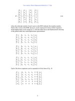
Clearly the operations in Eq. 11 and Eq. 12 are parallel to those in Eq. 11 and Eq. 12. If
we define
Beam and Frame Analysis: Force Method, Part II by S. T. Mau
127
−
EI
M
as “elastic load” in parallel to q as the real load,
then the two processes of finding shear and moment diagrams and rotation and deflection
diagrams are identical.
Shear and moment diagrams: qVM
Rotation and deflection diagrams: −
EI
M
θ
v
We can now define a “conjugate beam,” on which an elastic load of magnitude −M/EI is
applied. We can draw the shear and moment diagrams of this conjugate beam and the
results are actually the rotation and deflection diagrams of the original beam. Before we
can do that, however, we have to find out what kind of support or connection conditions
we need to specify for the conjugate beam.
This can be easily achieved by following the reasoning from left to right as illustrated in
the table below, noting that M and V of the conjugate beam corresponding to deflection
and rotation of the real beam, respectively.
Support and Connection Conditions of a Conjugated Beam
Original beam Conjugate beam
Support/connection v
v'=
θ
MVM VSupport/connection
Fixed 00
≠0 ≠0
00 Free
Free
≠0 ≠0
00
≠0 ≠0
Fixed
Hinge/Roller End 0
≠0
0
≠0
0
≠0
Hinge/Roller End
Internal Support 0
≠0 ≠0 ≠0
0
≠0
Internal Connection
Internal Connection
≠0 ≠0
0
≠0 ≠0 ≠0
Internal Support
At a fixed end of the original beam, the rotation and deflection should be zero and the
shear and moment are not. At the same location of the conjugate beam, to preserve the
parallel, the shear and moment should be zero. But, that is the condition of a free end.
Thus the conjugate bean should have a free end at where the original beam has a fixed
end. The other conditions are derived in a similar way.
Note that the support and connection conversion summarized in the above table can be
summarized in the following figure, which is easy to memorize. The various quantities
are also attached but the important thing to remember is a fixed support turns into a free
support and vise versa while an internal connection turns into an internal support and vise
versa.
Beam and Frame Analysis: Force Method, Part II by S. T. Mau
128
Conversion from a real beam to a conjuagte beam.
We can now summarize the process of constructing of the conjugate beam and drawing
the rotation and deflection diagrams:
(1) Construct a conjugate beam of the same dimension as the original beam.
(2) Replace the support sand connections in the original beam with another set of
supports and connections on the conjugate beam according to the above table. i.e.
fixed becomes free , free becomes fixed. etc.
(3) Place the M/EI diagram of the original beam onto the conjugate beam as a distributed
load, turning positive moment into upward load.
(4) Draw the shear diagram of the conjugate beam, positive shear indicates
counterclockwise rotation of the original beam.
(5) Draw the moment diagram of the conjugate beam, positive moment indicates upward
deflection.
Example 12. The beam shown has a constant EI and a length L, draw the rotation and
deflection diagrams.
A cantilever beam load by a moment at the tip.
Solution.
(1) Draw the moment diagram of the original beam.
Moment diagram.
θ
=0
v=0
V≠0
M
≠0
θ
≠0
v≠0
θ
=0
v=0
V≠0
M
=0
V≠0
M
=0
V=0
M
=0
V≠0
M
≠0
V=0
M
=0
R
eal
Conjugate
V≠0
M
≠0
θ
≠0
v≠0
θ
≠0
v=0
V≠0
M
=0
V≠0
M
=0
V=0
M
=0
V≠0
M
≠0
V=0
M
=0
θ
≠0
v=0
M
o
x
M
o
M
Beam and Frame Analysis: Force Method, Part II by S. T. Mau
129
(2) Construct the conjugate beam and apply the elastic load.
Conjagte beam and elastic load.
(3) Analyze the conjugate beam to find all reactions.
Conjagte beam, elastic load and reactions.
(4) Draw the rotation diagram ( the shear digram of the conjugate beam).
Shear(Rotation) diagram indicating clockwise rotation.
(5) Draw the deflection diagram ( the moment diagram of the conjugate beam).
Moment(Deflection) diagram indicating upward deflection.
Example 13. Find the rotation and deflection at the tip of the loaded beam shown. EI is
constant.
Find the tip rotation and deflection.
Solution. The solution is presented in a series of diagrams below.
M
o
2aa
x
M
o
/EI
x
M
o
/EI
M
o
L
/EI
M
o
L
2
/2EI
−
M
o
L
/EI
M
o
L
2
/2EI
Beam and Frame Analysis: Force Method, Part II by S. T. Mau
130
Solution process to find tip rotation and deflection.
At the right end (tip of the real beam):
Shear = 5aM
o
/3EI
θ
= 5aM
o
/3EI
Moment = 7a
2
M
o
/6EI v = 7a
2
M
o
/6EI
Example 14. Draw the rotation and deflection diagrams of the loaded beam shown. EI
is constant.
Beam example on rotation and deflection diagrams.
M
o
2aa
M
o
/2a
M
o
/2a
M
o
2aa
M
o
/EI
M
o
/EI
2aM
o
/3EI
A
M
o
/3EI
M
o
/EI
5aM
o
/3EI
7a
2
M
o
/6EI
aM
o
/EI
R
eactions
M
oment Diagram
Conjugate Beam
R
eactions
2aaa
P
Beam and Frame Analysis: Force Method, Part II by S. T. Mau
131
Solution. The solution is presented in a series of diagrams below. Readers are
encouraged to verify all numerical results.
Solution process for rotation and deflection diagrams.
2aaa
P
P
a
R
eactions
P
a/2
−
Pa
M
oment Diagram
2aaa
Conjugate Beam
P
a/2EI
P
a/EI
2aaa
R
eactions
P
a/2EI
P
a/EI
11Pa
2
/12EI
5Pa
2
/12EI
Shear(Rotation)Diagram
( Unit: Pa
2
/EI )
−1
−1/12
5/12
1/6
M
oment(Deflection) Diagram
( Unit: Pa
3
/EI )
a/6
−2701/7776=−0.35
−1/3=−0.33
P
/2
P
/2
Beam and Frame Analysis: Force Method, Part II by S. T. Mau
132
Problem 3. Draw the rotation and deflection diagrams of the loaded beams shown. EI is
constant in all cases.
(1)
(2)
(3)
(4)
(5)
Problem 3.
L
/2
L
/2
1 kN-m
L
/2
L
/2
1 kN
L
/2
L
/2
M
o
= 1 kN-m
L
/2
L
/2
1 kN
2aaa
2Pa
Beam and Frame Analysis: Force Method, Part II by S. T. Mau
133
Energy Method – Unit Load Method. The conjugate beam method is the preferred
method for beam deflections, but it cannot be easily generalized for rigid frame
deflections. We shall now explore energy methods and introduce the unit load method for
beams and frames.
One of the fundamental formulas we can use is the principle of conservation of
mechanical energy, which states that in an equilibrium system, the work done by
external forces is equal to the work done by internal forces.
W
ext
= W
int
(13)
For a beam or frame loaded by a group of concentrated forces P
i
, distributed forces q
j,
and
concentrated moments M
k
, where i, j, and k run from one to the total number in the
respective group, the work done by external forces is
W
ext
= Σ
2
1
P
i
∆
i
+Σ ∫
2
1
(q
j
dx) v
j
+ Σ
2
1
M
k
θ
k
(14)
where
∆
i,
v
j
, and
θ
k
are the deflection and rotation corresponding to P
i
, q
j
,and M
k
. For a
concentrated load, the load-displacement relationship for a linear system is shown below
and the work done is represented by the shaded triangular area. Similar diagrams can be
drawn for qdx and M.
Work done by a concentrated load.
For the work done by internal forces, we shall consider only internal moments, because
the effect of shear and axial forces on deflection is negligible. We introduce a new entity,
strain energy, U, which is defined as the work done by internal forces. Then
W
int
= U = Σ ∫
2
1
Md
θ
= Σ ∫
2
1
EI
dxM
2
(15)
L
oad
D
isplacement
∆
P
Beam and Frame Analysis: Force Method, Part II by S. T. Mau
134
where the summation is over the number of frame members, and the integration is over
the length of each member. For a single beam, the summation is redundant. The above
expression is derived as follows. The angle of rotation of an infinitesimal element
induced by a pair of internal moments is illustrated in the figure below.
Change of angle induced by internal moments.
The change of angle is related to the internal moment, according to Eq. 7 and Eq. 9, by
d
θ
=
EI
Mdx
which leads to Eq. 15.
Example 15. Find the rotation at the tip of the beam shown. EI is constant, and the
beam length is L.
Example on tip rotation.
Solution. We shall use the principle of conservation of mechanical energy to find the tip
rotation, which is denoted by
θ
o
. The work done by external forces is
W
ext
=
2
1
M
o
θ
o
x
dx
d
θ
M
M
M
o
x
dx