Fundamentals of Structural Analysis Episode 1 Part 9 pps
Bạn đang xem bản rút gọn của tài liệu. Xem và tải ngay bản đầy đủ của tài liệu tại đây (279.26 KB, 20 trang )
Beam and Frame Analysis: Force Method, Part III by S. T. Mau
155
Conjugate beam method to find
∆
b
’.
The deflection is computed as the moment at b of the conjugate beam.
∆
b
’ = (ΣM
b
) =
EI
1
(
2
1
2
PL
2
L
)(
3
L
+
2
L
)=
EI
PL
48
5
3
Downward.
Conjugate beam method to find
δ
bb
.
δ
bb
= (ΣM
b
) =
EI
1
[(
2
1
)(L)(L)] (
3
2
L)=
EI
L
3
3
Downward.
R
b
= −
bb
b
δ
∆
'
= −
16
5
P Upward.
(4) Find other reaction forces and draw the shear and moment diagrams. This is achieved
through a series of diagrams in the figure below.
P
a
b
∆
b
’
a
b
P
L/2EI
a
b
δ
bb
1
Conjugate beam
L
/2
L
/2
a
b
L
/E
I
Conjugate beam
2L/3
L
/3
Beam and Frame Analysis: Force Method, Part III by S. T. Mau
156
Reactions, shear, moment and deflection diagrams.
Example 25. Find all reactions of the same beam as in Example 24, but choose a
different redundant force. EI is constant.
Beam statically indeterminate to the first degree.
Solution. There are different ways of establishing a primary structure. For example,
inserting a hinge connection at any point along the beam introduces one condition of
construction and renders the resulting structure statically determinate. We now choose to
put the hinge at the fixed end, effectively selecting the end moment, M
a
, as the redundant
force.
P
a
b
5P /16
11P /16
3PL/16
V
M
5PL/32
∆
11P /16
−5P /16
−3PL/16
I
nflection point
L
/2
L
/2
L
/2
L
/2
P
a
b
Beam and Frame Analysis: Force Method, Part III by S. T. Mau
157
Primary structure and redundant moment M
a
.
The compatibility equation is established from the condition that the total rotation at a of
the primary structure due to the combined effect of the applied load and the redundant
force M
a
must be zero, which is required by the fixed end support.
Compatibility condition and principle of superposition.
θ
a
=
θ
'
a
+ M
a
θ
aa
= 0
L
/2
L
/2
P
a
b
M
a
P
a
b
P
a
b
a
b
=
+
θ
’
a
1
M
a
θ
aa
θ
a
=0
Beam and Frame Analysis: Force Method, Part III by S. T. Mau
158
The conjugate beam method is used to find
θ
'
a
and
θ
aa
.
Conjugate beam for
θ
'
a
.
From the conjugate beam, the rotation at point a is computed as the shear of the
conjugate beam at a.
θ
'
a
= (V
a
)= −(
EI
PL
16
2
)
To find
θ
aa
, the following figure applies.
Conjugate beam for
θ
aa
.
a
b
M
P
L/4
P
L/4EI
P
L
2
/16EI
a
b
1
a
b
M
1/EI
L
/6EI
1
L
/3EI
θ
aa
Conjugate beam
P
L
2
/16EI
P
L
2
/16EI
P
L
2
/16EI
L
/2EI
Conjugate beam
Beam and Frame Analysis: Force Method, Part III by S. T. Mau
159
From the conjugate beam, the rotation at point a is computed as the shear of the
conjugate beam at a.
θ
aa
= (V
a
)= −(
EI
L
3
)
The redundant moment is computed from the compatibility equation as
M
a
= −
aa
a
'
θ
θ
= −
16
3PL
This is the same end moment as obtained in Example 24. All reaction forces are shown
below.
Solution showing all reaction forces.
Example 26. Analyze the indeterminate beam shown below and draw the shear, moment,
and deflection diagrams. EI is constant.
Statically indeterminate beam with one redundant force.
Solution. We choose the reaction at the center support as the redundant force. The
compatibility condition is that the vertical displacement at the center support be zero.
The primary structure, deflections at center due to the load and the redundant force, etc.
are shown in the figure below. The resulting computation is self-evident.
L
L
w
P
a
b
5 P /16
11 P /16
3PL/16
L
/2
L
/2
Beam and Frame Analysis: Force Method, Part III by S. T. Mau
160
Principle of superposition used to find compatibility equation.
The compatibility condition is
∆
c
=
∆
c
’
+ R
c
δ
cc = 0
For such a simple geometry, we can find the deflections from published deflection
formulas.
∆
c
’
=
EI
lengthw
384
)(5
4
=
EI
Lw
384
)2(5
4
=
EI
wL
24
5
4
δ
cc
=
EI
lengthP
48
)(
3
=
EI
LP
48
)2(
3
=
EI
L
6
3
Hence
R
c
= −
4
5wL
Upward.
The reaction, shear, moment and deflection diagrams are shown below.
L
L
w
w
∆
c
’
c
R
c
R
c
δ
cc
=
+
∆
c
=0
Beam and Frame Analysis: Force Method, Part III by S. T. Mau
161
Reaction, shear, moment, and deflection diagrams.
Example 27. Outline the formulation of the compatibility equation for the beam shown.
Statically indeterminate beam with two redundant forces.
Solution. We choose the reaction forces at the two internal supports as the redundant
forces. As a result, the two conditions of compatibility are: the vertical displacements at
the internal support points be zero. The superposition of displacements involves three
loading conditions as shown in the figure below.
L
L
w
c
5wL/4
3wL/8
3wL/8
3wL/8
−3wL/8
5wL/8
-5wL/8
9wL
2
/128
∆
M
V
L
L
w
L
3/8L
3/4L
wL
2
/8
Beam and Frame Analysis: Force Method, Part III by S. T. Mau
162
Superposition of primary structure solutions.
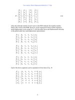
The two compatibility equations are:
∆
1
=
∆
1
’
+ R
1
δ
11
+ R
2
δ
12
= 0
∆
2
=
∆
2
’
+ R
1
δ
21
+ R
2
δ
22
= 0
These two equations can be put in the following matrix form.
L
L
w
L
∆
1
’
∆
2
’
L
L
w
L
R
1
δ
11
R
1
δ
21
R
1
1
2
1
2
L
L
w
L
R
2
δ
12
R
2
δ
22
R
2
1
2
L
L
w
L
+
+
=
∆
1
=0
∆
2
=0
2
1
Beam and Frame Analysis: Force Method, Part III by S. T. Mau
163
⎥
⎦
⎤
⎢
⎣
⎡
2212
1211
δδ
δδ
⎭
⎬
⎫
⎩
⎨
⎧
2
1
R
R
= −
⎭
⎬
⎫
⎩
⎨
⎧
'
'
2
1
∆
∆
Note that the square matrix at the LHS is symmetric because of Maxwell’s reciprocal
law. For problems with more than two redundant forces, the same procedures apply and
the square matrix is always symmetric.
While we have chosen support reactions as redundant forces in the above beam examples,
it is sometimes advantageous to choose internal moments as the redundant forces as
shown in the frame example below.
Example 28. Analyze the frame shown and draw the moment and deflection diagrams.
EI is constant for all members.
A rigid frame with one degree of redundancy.
Solution. We choose the moment at mid-span of the beam member as the redundant: M
c
.
Principle of superposition and compatibility equation.
L
2L
P
P
c
P
c
θ
c
’
M
c
θ
cc
M
c
+
=
θ
c
=0
Beam and Frame Analysis: Force Method, Part III by S. T. Mau
164
The compatibility equation is:
θ
c
=
θ
c
’ + M
c
θ
cc
= 0
To find
θ
’
c
, we use the unit load method. It turns out that
θ
c
’ = 0 because the contribution
of the column members cancels out each other and the contribution from the beam
member is zero due to the anti-symmetry of M and symmetry of m. Consequently, there
is no need to find
θ
cc
and M
c
is identically zero.
Unit load method to find relative angle of rotation at C.
The moment diagram shown above is the correctly moment diagram for the frame and the
deflection diagram is shown below.
Deflection diagram of the frame.
Example 29. Analyze the frame shown and draw the moment and deflection diagrams.
EI is constant for the two members.
c
θ
’
c
1
P
L
L
L
P
/2
P
/2
P
/2
P
/2
1/L 1/L
P
L/2
M
m
−1
∆
Beam and Frame Analysis: Force Method, Part III by S. T. Mau
165
A frame example with one degree of redundancy.
Solution. We choose the horizontal reaction at C as redundant: R
ch
Principle of superposition and compatibility equation.
The compatibility equation is:
∆
c
=
∆
c
’+ R
ch
δ
cc
= 0
We use the unit load method to compute
∆
c
’ and
δ
cc
.
Load diagrams for applied load and unit load.
M
o
c
L
L
M
o
c
L
L
M
o
c
L
L
c
L
L
R
ch
R
ch
δ
cc
∆
c
’
=
+
L
L
c
L
L
M
o
1
1
1
1
M
o
/L
M
o
/L
∆
c
=0
Beam and Frame Analysis: Force Method, Part III by S. T. Mau
166
Moment diagrams for applied load and unit load.
∆
c
’ = Σ ∫m
EI
Mdx
=
EI
1
3
1
( M
o
)( L)( L) =
EI
LM
3
2
o
δ
cc
= Σ ∫m
EI
mdx
=
EI
1
3
1
( L)( L)( L) (2)=
EI
L
3
2
3
∆
’
c
+ R
ch
δ
cc
= 0R
ch
= −
L
M
2
o
Load, moment, and deflection diagrams.
Example 30. Outline the formulation of the compatibility equation of the rigid frame
shown. EI is constant for all members.
A rigid frame with three degrees of redundancy.
M
o
L
M
m
L
L
M
o
M
o
/2L
M
o
/2
−
M
o
/2
M
o
/2L
M
o
/2L
M
o
/2L
L
L
P
Beam and Frame Analysis: Force Method, Part III by S. T. Mau
167
Solution. We choose three internal moments as the redundant forces. The resulting
primary structure is one with three hinges as shown (the circles at 1 and 3 are meant to
represent hinges). At each of the three hinges, the cumulative effect on the relative
rotation must be zero. That is the compatibility condition, which can be put in a matrix
form.
Primary structure and the relative rotation at each hinge.
⎥
⎥
⎥
⎦
⎤
⎢
⎢
⎢
⎣
⎡
333231
232221
312111
θθθ
θθθ
θθθ
⎪
⎭
⎪
⎬
⎫
⎪
⎩
⎪
⎨
⎧
3
2
1
M
M
M
= −
⎪
⎭
⎪
⎬
⎫
⎪
⎩
⎪
⎨
⎧
'
'
'
3
2
1
θ
θ
θ
The matrix at the LHS is symmetric because of the Maxwell’s reciprocal law.
Beam Deflection Formulas. For statically determinate beam configurations, simple
deflection formulas can be easily derived. They are useful for the solution of
indeterminate beam problems using the method of consistent deformations. Some of the
formulas are given in the table next page.
Approximate Methods for Statically Indeterminate Frames. As we can see from the
previous examples, the force method of analysis for frames is practical for hand
calculation only for cases of one to two degrees of redundancy. Although we can
computerize the process for high redundancy cases, an easier way for computerization is
through the displacement method, which is covered later in another unit. In the
meantime, for practical applications, we can use approximate methods for preliminary
design purposes. The approximate methods described herein will give good
approximation to the correct solutions.
P
1
2
3
θ
2
’
M
1
M
1
θ
11
θ
1
’
θ
3
’
M
1
θ
21
M
1
θ
31
M
1
M
2
θ
21
M
2
θ
22
M
2
θ
32
M
3
M
3
θ
31
M
3
θ
23
M
3
θ
33
θ
2
=0
θ
1
=0
θ
3
=0
P
Beam and Frame Analysis: Force Method, Part III by S. T. Mau
168
Beam Deflection Formulas
Beam Configuration Formulas for Any Point Formulas for Special Points
θ
= −
EI
M
o
(L-x)
v
=
EI
M
2
o
(L-x)
2
θ
ο
= −
EI
LM
o
v
o
=
EI
LM
2
2
o
θ
=
EI
P
2
(L
2
-x
2
)
v
= −
EI
PL
3
3
+
EI
Px
6
(3L
2
-x
2
)
θ
ο
=
EI
PL
2
2
v
o
= −
EI
PL
3
3
θ
=
EI
w
6
(L
3
-x
3
)
v
= −
EI
w
6
(L
4
-xL
3
)
θ
ο
=
EI
wL
6
3
v
o
= −
EI
wL
6
4
θ
= −
EI
P
16
( L
2
-4x
2
), x≤
2
L
v
= −
EI
P
48
(3L
2
x -4x
3
), x≤
2
L
θ
ο
= −
EI
PL
16
2
v
c
= −
EI
PL
48
3
θ
= −
EI
w
24
(L
3
-6Lx
2
+4x
3
)
v
= −
EI
w
24
(L
3
x-2x
3
L+x
4
)
θ
ο
= −
EI
wL
24
3
v
c
= v
max
= −
EI
wL
384
5
4
θ
= −
EIL
M
c
24
(L
2
-12x
2
), x≤
2
L
v
=
EIL
M
c
24
(L
2
x-4x
3
), x≤
2
L
θ
ο
= −
EI2
LM
c
4
v
max
=
EI
LM
c
327
2
, x=
32
L
θ
=
EIL
M
6
o
( 2L
2
-6Lx +3x
2
)
v
=
EIL
M
6
o
(2L
2
x-3Lx
2
+x
3
)
θ
ο
=
EI
LM
3
o
,
θ
1
= −
EI
LM
6
o
v
max
=
EI
LM
39
2
o
, x=
)33(
3
−
L
Convention: L=beam length, positive
θ
= counter-clockwise , positive v= upward
M
o
x
o
P
x
o
w
x
o
P
L
/2
L
/2
o
c
x
w
L
/2
L
/2
o
c
M
c
x
o
M
o
x
L
/2
L
/2
o
c
x
1
Beam and Frame Analysis: Force Method, Part III by S. T. Mau
169
The basic concept of the approximate methods is to assume the location of zero internal
moments. At the point of zero moment, the conditions of construction apply, i.e.,
additional equations are available. For rigid frames of regular geometry, we can “guess”
at the location of zero moment fairly accurately from experience. When enough
conditions of construction are added, the original problem becomes statically
determinate. We shall deal with two classes of problems separately according to loading
conditions.
Vertical Loads. For regular shaped rigid frames loaded with vertical floor loads such as
shown below, the deflection of the beams are such that zero moments exist at a location
approximately one-tenth of the span from each end.
Vertically loaded frame and approximate location of zero internal moment.
Once we put a pair of hinge-and-roller at the location of zero moment in the beams, the
resulting frame is statically determinate and can be analyzed easily. The following figure
illustrates the solution process.
Beams and columns as statically determinate components.
This approach neglects any shear force in the columns and axial force in the beams,
which is a fairly good assumption for preliminary design purposes.
Horizontal Loads. Depending on the configuration of the frame, we can apply either the
portal method or the cantilever method. The portal method is generally applicable to
low-rise building frames of no more than five stories high. The assumptions are:
L
0.1L
0.1L
roller hinge
Beam and Frame Analysis: Force Method, Part III by S. T. Mau
170
(1) Every mid-point of a beam or a column is a point of zero moment.
(2) Interior columns carry twice the shear as that of exterior columns.
Assumptions of the portal method.
The shear forces in the columns are computed first from the FBD above using the
horizontal equilibrium condition. The rest of the unknowns are computed from the FBDs
in the sequence shown in the following figure one at a time. Each FBD contains no more
than three unknowns. The curved arrows link dashed circles containing internal force
pairs.
FBDs to compute internal forces in the sequence indicated.
The assumptions of the portal method are based on the observation that the deflection
pattern of low-rise building frames is similar to that of the shear deformation of a deep
beam. This similarity is illustrated in the figure below.
2V
V
V
P
0.5P
0.25P
P
0.25P
0.5P
0.25P
0.25P
1
3
2
2
4
4
0.25P
P
0.25P
Beam and Frame Analysis: Force Method, Part III by S. T. Mau
171
Deflections of a low-rise building frame and a deep beam.
On the other hand, the cantilever method is generally applicable to high-rise building
frames, whose configurations are similar to those of vertical cantilevers. We can then
borrow the pattern of normal stress distribution in a cantilever and apply it to the high-rise
building frame as shown in the figure below.
Normal stress distribution in a cantilever and axial force distribution in a frame.
The assumptions of the cantilever method are:
(1) The axial forces in columns are proportional to the column’s distance to the center
line of the frame.
(2) The mid-points of beams and columns are points of zero moment.
The solution process is slightly different from that of the portal method. It starts from the
FBD of the upper story to find the axial forces. Then, it proceeds to find the column
shears and axial forces in beams one FBD at a time.
+
-
+
-
Beam and Frame Analysis: Force Method, Part III by S. T. Mau
172
This solution process is illustrated in the figure below. Note that the FBD of the upper
story cuts through mid-height, not the base, of the story.
Cantilever method and the FBDs.
In the figure above, the external columns have an axial force 2.5 times of that of the
interior columns because their distance to the center line is 2.5 time that of the interior
columns. The solution for the axial force S is obtained by taking moment about any point
on the mid-height line:
ΣM
a
= (1.5)(10)−(2.5S)(10)−S(7−3) =0 S=0.52 kN.
The rest of the computation goes from one FBD to another, each with no more than three
unknowns and each takes advantage of the results from the previous one. Readers are
encouraged to complete the solution of all internal forces.
10 kN
3m
3m
3m
3m
4m
10 kN
3m
3m
3m
3m
2m
10 kN
1.5m
S
2.5S
2.5S
a
S
a
2.5S
10 kN
S
2m
Beam and Frame Analysis: Force Method, Part III by S. T. Mau
173
Problem 6.
(1) Find all the reaction forces and moment at a and b. EI is constant and the beam
length is L.
(2) Find all the reaction forces and moments at a and b, taking advantage of the symmetry
of the problem. EI is constant.
(3) Find the horizontal reaction force at d.
(4) Find the internal moment at b.
Problem 6.
a
b
L
2L
P
L
a
b
c
d
2EI
E
I
E
I
M
b
ab
L
/2
L
/2
P
L
2L
P
L
b
c
d
2EI
E
I
E
I
a
Beam and Frame Analysis: Force Method, Part III by S. T. Mau
174