Fundamentals of Structural Analysis Episode 2 Part 2 ppt
Bạn đang xem bản rút gọn của tài liệu. Xem và tải ngay bản đầy đủ của tài liệu tại đây (249.15 KB, 20 trang )
Beam and Frame Analysis: Displacement Method, Part I by S. T. Mau
195
A three-span bridge frame.
Solution. Symmetry of the structure calls for the decomposition of the load into a
symmetric component and an anti-symmetric component.
Symmetric and anti-symmetric loads.
We shall solve both problems in parallel.
(1) Preparation. Note the stiffness computation in steps (c) and (d).
(a) Only nodes a and b are free to rotate when we take advantage of the
symmetry/anti-symmetry. Furthermore, if we use the modified stiffness for
the hinged end situation in member ab, then we need to concentrate on node b
only.
(b) FEM for member ab. The concentrated load of 50 kN creates FEMs at end a
and end b. The formula for a single transverse load in the FEM table gives us:
M
F
ab
= −
8
)( )( LengthP
= −
8
(10) (50)
= − 62.5 kN-m
M
F
ba
=
8
)( )( LengthP
=
8
(10) (50)
= 62.5 kN-m
(c) Compute DF at b (Symmetric Case):
DF
ba
: DF
bc
: DF
be
= 3EK
ab
: 2EK
bc
: 4EK
bc
= 3(
10
2EI
)
ab
: 2(
20
4EI
)
bc
: 4(
5
EI
)
bc
=
10
6
:
20
8
:
5
4
100 kN
5 m
5 m 5 m
20 m 10 m
a
b
c
d
e
f
4EI
2EI
2EI
E
I
E
I
50 kN
a
b
c
d
e
f
50 kN
50 kN
a
b
c
d
e
f
50 kN
Beam and Frame Analysis: Displacement Method, Part I by S. T. Mau
196
=
5
3
:
5
2
:
5
4
=
9
3
:
9
2
:
9
4
= 0.33 : 0.22: 0.45
(d) Compute DF at b (Anti-symmetric Case):
DF
ba
: DF
bc
: DF
be
= 3EK
ab
: 6EK
bc
: 4EK
bc
= 3(
10
2EI
)
ab
: 6(
20
4EI
)
bc
: 4(
5
EI
)
bc
=
10
6
:
20
24
:
5
4
=
5
3
:
5
6
:
5
4
=
13
3
:
13
6
:
13
4
= 0.23 : 0.46: 0.21
(e) Assign DFs at a and e: DF is one at a and zero at e.
(2) Tabulation. We need to include only nodes a, b and e in the table below.
Moment Distribution Table for a Symmetric Case and an Anti-symmetric Case
Symmetric Case Anti-symmetric Case
Node abeabe
Member ab bc be ab bc be
DF
1 0.33 0.22 0.45 0 1 0.23 0.46 0.31 0
MEM M
ab
M
ba
M
bc
M
be
M
eb
M
ab
M
ba
M
bc
M
be
M
eb
EAM
FEM
−62.5
62.5
−62.5
62.5
DM
62.5 62.5
COM
31.3 31.3
DM
−31.0 −20.6 −42.2 −21.6 −43.2 −29.0
COM
0.0
−21.1
0.0
−14.5
SUM
0.0 62.8
−20.6 −42.2 −21.1
72.2
−43.2 −29.0 −14.5
The solution to the original problem is the superposition of the two solutions in the above
table.
M
ab
= 0.0 + 0.0 = 0.0 kN-m
M
ba
= 62.8 + (72.2) = 135.0 kN-m
M
bc
= −20.6 + (−43.2) = −63.8 kN-m
M
be
= −42.2 + (−29.0) = −71.2 kN-m
M
eb
= −21.1 + (−14.5) = −35.6 kN-m
The superposition for the right half of the structure requires caution: moments at the right
half are negative to those at the left half in the symmetric case and are of the same sign in
the anti-symmetric case.
Beam and Frame Analysis: Displacement Method, Part I by S. T. Mau
197
M
dc
= 0.0 + 0.0 = 0.0 kN-m
M
cd
= −62.8 + (72.2) = 9.4 kN-m
M
cb
= 20.6 + (−43.2) = −22.6 kN-m
M
cf
= 42.2 + (−29.0) = 13.2 kN-m
M
fc
= 21.1 + (−14.5) = 6.6 kN-m
As expected, the resulting moment solution is neither symmetric nor anti-symmetric.
(3) Post Moment-Distribution Operations. The moment and deflection diagrams are
shown below.
Moment and deflection diagrams.
Example 9. Find all the member-end moments of the frame shown. EI is constant for
all members.
A frame with two DOFs.
2 m
2 m
2 m
4 kN
a
b
c
d
182.5
22.6
9.4
71.2
−63.8
−35.6
−135
−13.2
6.6
I
nflection point
Beam and Frame Analysis: Displacement Method, Part I by S. T. Mau
198
Solution.
(1) Preparation. Note the stiffness computation in step (c).
(a) Only nodes b and c are free to rotate. There is no side-sway because the
support at c prevents that. Only the transverse load between nodes a and b will
create FEMs at a and b.
(b) FEM for member ab. The formula for a single transverse load in the FEM
table gives us, as in Example 5:
M
F
bc
= − 2 kN-m
M
F
cb
= 2 kN-m
(c) Compute DF at b:
DF
ba
: DF
bc
= 4EK
ab
: 4EK
bc
= 4(
L
EI
)
ab
: 4(
L
EI
)
bc
=
4
4
:
2
4
= 0.33 : 0.67
(d) Compute DF at c:
DF
cb
: DF
cd
= 4EK
bc
: 4EK
cd
= 4(
L
EI
)
ab
: 4(
L
EI
)
bc
=
2
4
:
2
4
= 0.5 : 0.5
(e) Assign DF at a and d: DF is one at a and d.
(2) Tabulation.
Moment Distribution Table for a Two-DOF Frame
Node ab cd
Member ab bc cd
DF 0 0.33 0.67 0.5 0.5 0
MEM M
ab
M
ba
M
bc
M
cb
M
cd
M
dc
EAM
FEM -2 +2
DM -0.67 -1.33
COM -0.33 -0.67
DM +0.33 +0.34
COM +0.17 +0.17
DM -0.06 -0.11
COM -0.03 -0.06
DM +0.03 +0.03
COM +0.02
SUM -2.36 +1.27 -1.27 -0.37 +0.37 +0.19
(3) Post Moment-Distribution Operations. The member-end shear forces (underlined) are
determined from the FBD of each member. The axial forces are determined from the
Beam and Frame Analysis: Displacement Method, Part I by S. T. Mau
199
shear forces of the joining members. The reaction at the support at node c is determined
from the FBD of node c.
FBDs of the three members and node c.
The moment and deflection diagrams are shown below.
Moment and deflection diagrams.
Treatment of Side-sway. In all the example problems we have solved so far, each
member maybe allowed to have end-node rotations but not end-node translations
perpendicular to the member length direction. Consider the two problems shown below.
4 kN
a
b
c
d
2.36 kN-m
1.27 kN-m
2.27 kN
1.73 kN
b
1.27 kN-m
0.37 kN-m
0.81 kN
0.81 kN
1.73 kN
1.73 kN
0.37 kN-m
0.17 kN-m
0.28 kN
0.28 kN
0.81 kN
0.81 kN
0.81 kN
0.81 kN
1.73 kN
0.28 kN
R
eaction
= 2.01 kN
2 m
2 m
2 m
−2.36
−1.27
2.18
0.37
−0.19
I
nflection point
c
c
Beam and Frame Analysis: Displacement Method, Part I by S. T. Mau
200
A frame without side-sway and one with side-sway.
Nodes b and c of both frames are free to rotate, but no translation movement of nodes is
possible in the frame at left. For the frame at right, nodes b an c are free to move
sidewise, thus creating side-sway of members ab and cd. Note that member bc still does
not have side-sway, because there is no nodal movement perpendicular to the member
length direction.
As shown in the figure below, side-sway of a member can be characterized by a member
rotation,
φ
, which is different from member nodal rotation. The member rotation is the
result of relative translation movement of the two member-end nodes in a direction
perpendicular to the member length direction, defined as positive if it is a clockwise
rotation, same way as for nodal rotations.
φ
=
L
Ä
(6)
where
∆
is defined in the figure and L is the length of the member.
A member with side-sway.
The moment-rotation formula is
M
ab
= M
ba
=
−
6EK
φ
(7)
2 m
2 m
2 m
4 kN
a
b
c
d
b
2 m
2 m
2 m
4 kN
a
b
c
d
∆∆
∆
φ
M
ba
=
−
6EK
φ
M
ab
=
−
6EK
φ
E
I, L
a
Beam and Frame Analysis: Displacement Method, Part I by S. T. Mau
201
As indicated in the figure above, to have a unit side-sway angle takes −6EK of a pair of
member-end moments, while holding nodal rotation to zero at both ends. The member-
end shear forces are not shown.
We can easily develop a moment distribution process that includes the side-sway. The
process, however, is more involved than the one without the side-sway and tends to
diminish the advantage of the moment distribution method. A better method for treating
side-sway is the slope-deflection method, which is introduced next after the derivation of
the key formulas which are central to both the moment distribution method and the slope-
deflection method.
Derivation of the Moment-Rotation(M-
θ
and M-
φ
)Formulas. We need to derive the
formula for the standard model shown below in detail, the other formulas can be obtained
by the principle of superposition.
The standard model with the far-end fixed and the near-end hinged.
There are different ways to derive the moment –rotation formula, but the direct
integration method is the shortest and most direct way. We seek to show
M
ba
= 4EK
θ
b
&M
ab
= 2EK
θ
b
The governing differential equation is
EI V’’ = M(x)
Using the shear force expression at node a, we can write
M(x) = M
ab
−(M
ab
+M
ba
)
L
x
The second order differential equation, when expressed in terms of the member-end
moments, becomes
EI v’’ = M
ab
−(M
ab
+M
ba
)
L
x
θ
b
M
ab
M
ba
a
b
E
I,L
x
(M
ab
+M
ba
)/L
v
Beam and Frame Analysis: Displacement Method, Part I by S. T. Mau
202
Integrating once, we obtain
EI v’ = M
ab
(x) −(M
ab
+M
ba
)
L
x
2
2
+ C
1
The integration constant is determined by using the support condition at the left end:
At x=0, v’=0, C
1
=0
The resulting first order differential equation is
EI v’ = M
ab
(x) −(M
ab
+M
ba
)
L
x
2
2
Integrating again, we obtain
EI v= M
ab
2
2
x
−(M
ab
+M
ba
)
L
x
6
3
+ C
2
The integration constant is determined by the support condition at the left end:
At x=0, v=0, C
2
=0
The solution in v becomes
EI v= M
ab
2
2
x
−(M
ab
+M
ba
)
L
x
6
3
Furthermore, there are two more boundary conditions we can use to link the member-end
moments together:
At x=L, v=0, M
ba
= 2 M
ab
At x=L, v’= −
θ
b
,
θ
b
=
EI
ML
ba
4
Thus,
M
ba
= 4EK
θ
b
&M
ab
= 2EK
θ
b
Once the moment-rotation formulas are obtained for the standard model, the formulas for
other models are obtained by superposition of the standard model solutions as shown in
the series of figures below.
Beam and Frame Analysis: Displacement Method, Part I by S. T. Mau
203
Superposition of two standard models for a hinged end model solution.
θ
b
M
ab
=2EK
θ
b
M
ba
=4EK
θ
b
a
b
E
I,L
M
ab
=
−
2EK
θ
b
M
ba
=
−
EK
θ
b
a
b
E
I,L
θ
b
Μ
ab
=0
M
ba
=3EK
θ
b
a
b
E
I,L
θ
a
=
−0.5
θ
b
=
+
Beam and Frame Analysis: Displacement Method, Part I by S. T. Mau
204
Superposition of two standard models for a symmetric model solution.
θ
b
M
ab
=2EK
θ
b
M
ba
=4EK
θ
b
a
b
E
I,L
M
ab
=−4EK
θ
b
M
ba
=
−
2EK
θ
b
a
b
E
I,L
θ
b
M
ba
=2EK
θ
b
a
b
E
I,L
θ
a
= −θ
b
=
+
M
ab
=
−
2EK
θ
b
Beam and Frame Analysis: Displacement Method, Part I by S. T. Mau
205
Superposition of two standard models for an anti- symmetric model solution.
The superposition of standard models to obtain the solution for a translation model
requires an additional step in creating a rigid-body rotation of the member without
incurring any member-end moments. Two standard models are then added to counter the
rotation at member-ends so that the resulting configuration has zero rotation at both ends
but a side-sway for the whole member.
θ
b
M
ab
=2EK
θ
b
M
ba
=4EK
θ
b
a
b
E
I,L
M
ab
=4EK
θ
b
M
ba
=2EK
θ
b
a
b
E
I,L
θ
b
M
ba
=6EK
θ
b
a
b
E
I,L
θ
a
=θ
b
=
+
M
ab
=6EK
θ
b
Beam and Frame Analysis: Displacement Method, Part I by S. T. Mau
206
Superposition of a rigid-body solution and two standard models for a side-sway solution.
φ
M
ab
=2EK
φ
M
ba
=4EK
φ
a
b
E
I,L
M
ab
=4EK
φ
M
ba
=2EK
φ
a
b
E
I,L
φ
M
ba
=6EK
φ
a
b
E
I,L
φ
=
+
M
ab
=6EK
φ
a
b
E
I,L
∆
φ
+
φ
Beam and Frame Analysis: Displacement Method, Part I by S. T. Mau
207
Problem 1. Find all the member-end moments of the beams and frames shown and draw
the moment and deflection diagrams.
(1) (2)
(3)
(4) (5)
(6) (7)
Problem 1.
2 m
2 m
3 m
a
c
b
3 kN/m
4 kN
2EI
E
I
2 m
2 m
3 m
a
cb
8 kN
2EI
E
I
2 kN-m
50 kN
ab
cd
50 kN
2 m 2 m
2 m 2 m 4 m
50 kN
ab
c
4 m 4 m
4 m
8 m
2EI
2EI
E
I
E
I
2EI2EI
50 kN
ab
c
4 m 4 m
4 m
8 m
E
I
2EI2EI
2 m
2 m
2 m
4 kN
a
b
c
d
2 m
2 m
2 m
4 kN
a
b
c
d
d
d
Beam and Frame Analysis: Displacement Method, Part I by S. T. Mau
208
Fixed-End Moments
M
F
Loads M
F
−
8
PL
8
PL
− ab
2
PL − a
2
bPL
− a(1-a)PL a(1-a)PL
−(6−8a+3a
2
)
12
22
wLa
(4-3a)
12
23
wLa
−
12
2
wL
12
2
wL
−
20
2
wL
12
2
wL
−
96
5
2
wL
96
5
2
wL
− b(2a-b)M a(2b-a)M
Note: Positive moment acts clockwise.
aL
w
L
w
L
w
L
w
L
/2
L
/2
P
aL
aL
P
P
aL
bL
PP
M
bL
aL
209
Beam and Frame Analysis: Displacement Method
Part II
3. Slope-Deflection Method
The slope-deflection method treats member-end slope(nodal rotaton
θ
) and
deflection(nodal translation
∆
) as the basic unknowns. It is based on the same approch as
that of the moment distribution method with one difference: the slopes and deflections
are implicitly and indirectly used in the moment distribution method but explicitly used
in the slope-deflection method. When we “unlock” a node in the moment distribution
process, we implicitly rotate a node until the moment at the node is balanced while all
other nodes are “locked”. The process is iterative because we balance the moment one
node at a time. It is implicit because we need not know how much rotation is made in
order to balance a node. In the slope deflection method, we express all member-end
moments in terms of the nodal slope and deflection unknowns. When we write the nodal
equilibrium equations in moment, we obtain the equilibrium equations in terms of nodal
slope and deflection unknowns. These equations, equal in number to the unknown slopes
and deflections, are then solved directly.
We shall use a simple frame to illustrate the solution process of the slope-deflection
method.
A simple frame problem to be solved by the slope-deflection method.
We observe there are three nodes, a, b, and c. Only node b is free to rotate and the nodal
rotation is denoted by
θ
b
. This is the only basic unknown of the problem. We seek to
express the moment equilibrium condition at node b in terms of
θ
b
. This is achieved in
two steps: express moment equilibrium of node b in terms of member-end moments and
then express member-end moments in terms of
θ
b
. A simple substitution results in the
desired equilibrium equation for
θ
b
.
The figure below illustrates the first step.
100 kN-m
E
I, L
E
I, L
a
c
b
Beam and Frame Analysis: Displacement Method, Part II by S. T. Mau
210
Moment equilibrium at node b expressed in terms of member-end moments.
The moment equilibrium at node b calls for
Σ M
b
= 0 (8)
which is expressed in terms of member-end moments as
M
ba
+ M
bc
= 100 (8)
As we have learned in the moment distribution method, the member-end moments are
related to nodal rotation by
M
ba
= (4EK)
ab
θ
b
(9)
M
bc
= (4EK)
bc
θ
b
(9)
By substitution, we obtain the equilibrium equation in terms of
θ
b
,
[(4EK)
ab
+(4EK)
bc
]
θ
b
= 100 (10)
Solving for
θ
b
, noting in this case (4EK)
ab
=(4EK)
bc
=4EK, we obtain
θ
b
= 12.5
EK
1
Consequently, when we substitute
θ
b
back to Eq. 9, we obtain
100 kN-m
E
I, L
E
I, L
a
c
b
b
b
M
ba
M
ba
M
bc
M
bc
Beam and Frame Analysis: Displacement Method, Part II by S. T. Mau
211
M
ba
= (4EK)
ab
θ
b
= (4EK )(12.5)
EK
1
= 50 kN-m
M
bc
= (4EK)
bc
θ
b
= (4EK )(12.5)
EK
1
= 50 kN-m
Furthermore, the other member-end moments not needed in the equilibrium equation at
node b are computed using the moment-rotation formula as shown below.
M
ab
= (2EK)
ab
θ
b
= (2EK )(12.5)
EK
1
= 25 kN-m
M
cb
= (2EK)
bc
θ
b
= (2EK )(12.5)
EK
1
= 25 kN-m
The above solution process maybe summarized below:
(1) Identify nodal rotations as degrees-of-freedom (DOFs).
(2) Identify nodal equilibrium in terms of member-end moments.
(3) Express member-end moments in term of nodal rotation.
(4) Solve for nodal rotation.
(5) Substitute back to obtain all member-end moments.
(6) Find other quantities such as member-end shears, etc.
(7) Draw the moment and deflection diagrams.
We skip the last two steps because these are already done in the moment distribution
section.
Example 10. Find all the member-end moments of the beam shown. EI is constant for al
members.
Beam problem with a SDOF.
Solution. We observe that there is only one DOF, the rotation at b:
θ
b
.
The equation of equilibrium is
Σ M
b
= 0, or M
ba
+ M
bc
= 30
30 kN-m
a
b
c
10 m
5 m
Beam and Frame Analysis: Displacement Method, Part II by S. T. Mau
212
Before we express the member-end moments in terms of nodal rotation
θ
b
, we try to
simplify the expression of the different EKs of the two members by using a common
factor, usually the smallest EK among all EKs.
EK
ab
: EK
bc
=
10
EI
:
5
EI
= 1 : 2
EK
bc
= 2EK
ab
= 2EK,
EK
ab
= EK
Now we are ready to write the moment-rotation formulas
M
ba
= (4EK)
ab
θ
b
= 4EK
θ
b
M
bc
= (4EK)
bc
θ
b
= 8EK
θ
b
By substitution, we obtain the equilibrium equation in terms of
θ
b
,
[(4EK)
+(8EK)]
θ
b
= 30
Solving for
θ
b
and EK
θ
b
, we obtain
EK
θ
b
= 2.5
θ
b
= 2.5
EK
1
Consequently,
M
ba
= (4EK)
ab
θ
b
= (4EK )
θ
b
= 10 kN-m
M
bc
= (4EK)
bc
θ
b
= (8EK )
θ
b
= 20 kN-m
M
ab
= (2EK)
ab
θ
b
= (2EK )
θ
b
= 5 kN-m
M
cb
= (2EK)
bc
θ
b
= (4EK )
θ
b
= 10 kN-m
Note that we need not know the absolute value of EK if we are interested only in the
value of member-end moments. The value of EK is needed only when we want to know
the nodal rotation.
For problems with more than one DOF, we need to include contribution of nodal
rotations from both ends of a member to the member-end moments:
Beam and Frame Analysis: Displacement Method, Part II by S. T. Mau
213
M
ab
= (4EK)
ab
θ
a
+ (2EK)
ab
θ
b
(11)
M
ba
= (4EK)
ab
θ
b
+ (2EK)
ab
θ
a
(11)
Eq. 11 is easy to remember; the near-end contribution factor is 4EK and the far-end
contribution factor is 2EK.
Example 11. Find all the member-end moments of the beam shown. EI is constant for al
members.
Beam problem with two DOFs.
Solution. We observe that there are two DOFs, the rotations at nodes b and c:
θ
b
and
θ
c
,
respectively.
The two equations of equilibrium are:
Σ M
b
= 0 M
ba
+ M
bc
= 0
and
Σ M
c
= 0 M
cb
+ M
cd
= 30
Since EI is constant for all members, we can write
K
ab
:K
bc
: K
cd
=
3
EI
:
5
EI
:
5
EI
= 5 : 3 : 3 = 1.67 : 1 : 1
Thus,
EK
ab
= 1.67EK,
EK
bc
= EK,
EK
cd
= EK
The moment-rotation formulas can be written as, for the four member-end moments
appearing in the two equilibrium equations,
3m 5m 5m
a
b
c
d
30 kN-m
Beam and Frame Analysis: Displacement Method, Part II by S. T. Mau
214
M
ba
= (4EK)
ab
θ
b
= 6.68EK
θ
b
M
bc
= (4EK)
bc
θ
b
+(2EK)
bc
θ
c
= 4EK
θ
b
+2EK
θ
c
M
cb
= (4EK)
bc
θ
c
+(2EK)
bc
θ
b
= 4EK
θ
c
+2EK
θ
b
M
cd
= (4EK)
cd
θ
c
= 4EK
θ
c
Note that both rotations at node b and rotation at node c contribute to the member-end
moments, M
bc
and M
cb
.
By substituting the moments by rotations, we obtain the two equilibrium equations in
terms of
θ
b
and
θ
c
.
10.68 EK
θ
b
+ 2EK
θ
c
= 0
2EK
θ
b
+ 8EK
θ
c
= 30
It is advantageous to treat EK
θ
b
and EK
θ
c
as unknowns.
10.68 (EK
θ
b
) + 2 (EK
θ
c
) =0
2 (EK
θ
b
) + 8 (EK
θ
c
)= 30
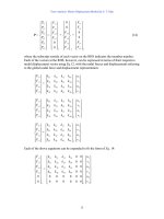
If we choose to put the above equation into a matrix from, the matrix at the LHS
would be symmetric, always:
⎥
⎦
⎤
⎢
⎣
⎡
82
210.68
⎭
⎬
⎫
⎩
⎨
⎧
c
b
θ
θ
EK
EK
=
⎭
⎬
⎫
⎩
⎨
⎧
30
0
Solving the two equations, we obtain
(EK
θ
b
) = −0.74 kN-m
(EK
θ
c
) = 3.93 kN-m
Substitute back for member-end moments:
M
ba
= 6.68EK
θ
b
= −4.92 kN-m
M
bc
= 4EK
θ
b
+2EK
θ
c
= 4.92 kN-m
M
cb
= 4EK
θ
c
+2EK
θ
b
= 14.26 kN-m