Fundamentals of Structural Analysis Episode 2 Part 5 pdf
Bạn đang xem bản rút gọn của tài liệu. Xem và tải ngay bản đầy đủ của tài liệu tại đây (223.9 KB, 20 trang )
Influence Lines by S. T. Mau
255
Influence line solutions.
Example 2. Construct the influence lines for R
a
, R
d
, M
d
, M
b
, V
d
, V
cR
and V
cL
of the beam
shown.
Beam with an internal hinge.
a
b
c
d
1
R
a
a
b
c
d
1
R
b
a
b
cd
1
V
c
a
b
c
d
1
M
c
α
h
α
h
a
b
cd
1
V
d
a
b
c
d
1
M
d
a
b
c
d
Influence Lines by S. T. Mau
256
Solution. Applications of the Müller-Breslau Principle yield the following solutions.
Influence line solutions.
ac
d
1
R
a
a
c
d
1
R
d
a
b
c
d
1
M
d
a
b
c
d
1
M
b
a
b
c
d
1
V
b
a
b
c
d
V
cR
1
a
b
c
d
V
cL
1
Influence Lines by S. T. Mau
257
Influence lines for statically indeterminate beam and frames. The Müller-Breslau
Principle is especially useful in sketching influence lines for a statically indeterminate
beam or frame. The process is the same as that for a statically determinate structure but
the precise shape cannot be obtained without further computation, which is very
involved. We shall demonstrate only the qualitative solution process without any
computations.
Example 3. Sketch the influence lines for R
a
, R
c
, V
d
, and M
d
of the beam shown.
Two-span beam example.
Solution. The influence lines are curved because the virtual displacements must be
curved to accommodate the support constraints.
Influence line solutions.
Example 4. Sketch the influence lines for M
a
of the frame shown.
a
b
c
d
a
b
c
d
1
R
a
R
c
a
b
c
d
1
a
b
c
d
V
d
1
a
b
c
d
M
d
1
Influence Lines by S. T. Mau
258
Frame example.
Solution. According to the Müller-Breslau Principle, we need to make a cut at section a
and impose a unit relative rotation at the cut. Try-and error leads to the following sketch
that satisfies all constraints of the principle.
Sketch of influence line for M
a
of section a.
Example 5. Place uniformly distributed loads anywhere on the second floor of the frame
shown in Example 4 to maximize M
a
.
Using the influence line of M
a
as the guide, we place the load at locations as shown in the
following figure for maximum positive and negative moments at section a.
Loading pattern for maximum positive M
a
(left) and negative M
a
(right).
Applications of influence lines. The following exmaples illustrate the use of influence
lines to find the maximum of a desired design parameter.
1
a
a
a
a
Influence Lines by S. T. Mau
259
Example 6. Find the maximum moment at c for (1) a single load of 10 kN and (2) a pair
of 10- kN loads 1 m apart.
A simply supported beam.
Solution. The influence line for M
c
has been obtained earlier and is reproduced below.
Influence line for M
c
.
For a single load of 10 kN, we place it at the location of the peak of the influence line and
we compute
(M
c
)
max
= 10 kN (2.5 kN-m/kN)=25 kN-m.
For the pair of loads, we place them as shown below.
(M
c
)
max
= 10 kN (2.5 kN-m/kN)+ 10 kN (2.0 kN-m/kN)=45 kN-m.
For this case, it turns out that the pair of loads can be placed anywhere within 1 m of the
center point of the beam and the resulting maximum M
c
would be the same.
Example 7. Find the maximum shear at c for uniformly distributed loads of intensity 10
kN/m and unlimited length of coverage.
5 m 5 m
ac
b
2.5 kN-m/kN
M
c
2.5
M
c
1 m
2.0
10 kN
10 kN
Influence Lines by S. T. Mau
260
Beam with an overhang.
Solution. The influence line as constructed earlier is reproduced below.
Influence line for V
c
.
In beam design, the sign of shear force is often not important. Thus, we want to find the
maximum shear regardless of its sign. From the influence line, the following load
application produces the maximum shear force.
Loads to maximize V
c
.
The maximum value of V
c
is computed using the influence line and the area below the
influence line of the loaded portion:
(V
c
)
max
= (−)10 [(
2
1
)(5)(
2
1
)] + (−)10 [(
2
1
)(5)(
2
1
)] = −25 kN.
Deflection Influence Lines. In design we need to answer the question: what is the
maximum deflection of any given point on the center line of a beam? The answer is in
the influence line for deflections. Surprisingly, the deflection influence line is identical
to the deflection curve under a unit load applied at the point of interest.
Consider the beam and unit load configuration shown below.
a
b
c
d
5 m 5 m
5 m
a
b
cd
V
c
5 m
5 m 5 m
1/2
1/2
1/2
a
b
c
d
5 m 5 m
5 m
10 kN-m 10 kN-m
Influence Lines by S. T. Mau
261
Deflection at j due to a unit load at i.
According to the Maxwell’s Reciprocal Theorem, however,
δ
ji
=
δ
ij
And,
δ
ij
is defined in the figure below:
Influence line for deflection at j.
Thus, to find the deflection influence line of a point, we need only to find the deflection
curve corresponding to a unit load applied at the point.
i
x
1
j
δ
ji
i
1
j
δ
ij
Influence Lines by S. T. Mau
262
Problem 1.
(1) Construct the influence lines of V
b
and M
d
of the beam shown and find the maximum
value of each for a distributed load of intensity 10 kN/m and indefinite length of
coverage.
Problem 1. (1)
(2) Construct the influence lines of V
bL
and V
bR
of the beam shown and find the
maximum value of each for a distributed load of intensity 10 kN/m and indefinite
length of coverage.
Problem 1. (2)
(3) Construct the influence lines of V
cL
,
V
cR
and M
c and
M
e
of the beam shown.
Problem 1. (3).
(4) Sketch the influence line of V
a
of the frame shown.
Problem 1. (4)
a
b
c
d
5 m 5 m
5 m
a
b
c
d
5 m 5 m
5 m
a
b
c
d
2.5 m
5 m
5 m
2.5 m
e
a
Influence Lines by S. T. Mau
263
3. Truss Influence Lines
For a truss, the question relevant in design is: How does a member force change when a
unit load moves along the span of the truss? The answer is again in the influence line,
but the truss itself only accepts loads at the joints. Thus, we need to examine how a load,
moving continuously along the truss span, transmits its force to the truss joints.
As shown in the figure below, a truss has a floor system that transmits a load from the
floor slab (not shown) to the stringers, then to the floor beams. The floor beams transmit
force to the joints of the truss. Thus, a plane truss accepts load only at the joints.
Floor system of a bridge truss.
As a load is applied between the joints, the load is transmitted to the two encompassing
joints by the equivalent of a simply supported beam. The resulting effect is the same as
that of two forces with the magnitude as shown acting at the two joints. The magnitude
of each force is a linear function of the distance from each joint.
Transmission of force to truss joints.
Assuming that a member force S due to a downward unit load at joint i is S
i
and the
member force S due to a downward unit load at joint j is S
j
, then the member force due to
a unit load applied between joints i and j and located from joint i by a distance of a is:
1
a
L
L
L
aL −
L
a
Stringer
Stringer
Floor
b
eam
Floor
b
eam
i
i
j
j
Influence Lines by S. T. Mau
264
S = (
L
aL −
) S
i
+ (
L
a
) S
j
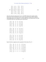
We conclude that the force of any member due to a load applied between two joints can
be computed by a linear interpolation of the member force due to the same load applied at
each joint separately. The implication in constructing influence lines is that we need only
to find the member force due to a unit load applied at the truss joints. When the member
force is plotted against the location of the unit load, we can connect two adjacent points
by a straight line.
Example 8. Construct the influence line of member forces F
IJ
, F
CD
, and F
CJ
. Load is
applied only at the level of lower chord members.
Truss example for influence line construction.
Solution. We shall use the method of section and make a cut through I-J and C-D. Two
FBDs are needed: one for loads applied to the right of the section and the other for loads
to the left of the section.
FBD for unit load acting at x > 6m.
ΣM
C
=0 F
IJ
= −1.5 R
A
(x > 6m)
4 m
2@3 m = 6 m
B
C
HI
R
A
F
IJ
A
1
x
4 m
6@3 m = 18 m
A
BCDE
G
HI J KL
F
F
CJ
F
CD
J
Influence Lines by S. T. Mau
265
ΣM
J
=0, F
CD
= 3.0 R
G
(x > 9m)
ΣF
y
=0 F
CJ
= −1.25 R
G
(x > 6m)
FBD for unit load acting at x < 6m.
ΣM
C
=0 F
IJ
= − 3.0 R
G
(x < 6m)
ΣM
J
=0 F
CD
= 3.0 R
G
(x < 9m)
ΣF
y
=0 F
CJ
= 1.25 R
G
(x < 6m)
We need to find influence lines of R
A
and R
G
first before we can construct the influence
lines of the three members IJ, CD and CJ. Use the FBD of the whole truss as shown
below, we can easily obtain the expression for the two support reactions.
FBD of the whole truss to find reactions.
F
4 m
4@3 m = 12 m
C
DE
G
IJ KL
F
IJ
R
G
4 m
6@3 m = 18 m
A
BCDE
G
HI J KL
R
G
R
A
x
1
1
x
F
CJ
F
CD
A
Influence Lines by S. T. Mau
266
ΣM
A
=0 R
G
=
18
x
ΣM
G
=0 R
A
=
18
18 x−
The influence lines of the two support reactions are identical in shape to those of a simply
supported beam and are shown below together with the influence lines of F
IJ
, F
CD
, and
F
CJ
which are obtained by cut-and-paste of and applying the proper factors to the reaction
influence lines.
Constructing member force influence lines using support reaction influence lines.
From the above three influence lines, we observe that the upper chord-member IJ is
always in compression, the lower chord-member CD is always in tension and web-
1
1
3
1.5
1
3
3
1.5
1.25
1.25
0.625
0.41
R
A
R
G
6 m
9 m
F
IJ
F
CD
F
CJ
Influence Lines by S. T. Mau
267
member CJ can be in tension or compression depending on whether the load is to the left
or right of the panel.
Example 9. For the truss in Example 8 find the maximum force in member CJ for the
four kinds of loads shown in the figure below.
A single load, a group load, and uniform loads with indefinite and finite length.
(1) Single concentrated load
Placing load at peak point on the influence line.
(F
CJ
)
max
= 2 (0.625)= 1.25 kN.
(2) Group load: The group load can be applied in any orientation. Try-and-error leads to
the following location of the group load.
Placing the group load to maximize F
CJ
.
1kN 1kN
2 kN
1m
2m
2 kN
10 kN/m 10 kN/m
x
6 m
1.25
1.25
0.625
0.41
F
CJ
2 kN
1.25
1.25
0.625
0.41
F
CJ
2 kN
1kN 1kN
1m2m
7 m
9 m
Influence Lines by S. T. Mau
268
(F
CJ
)
max
= −[2(0.625)+1(0.625)(7/9)+1(0.625)(6/9)]= −2.15 kN
This is a compression force maximum. To find the tension force maximum, the group
load is placed in a different way as shown below.
Placing group load for maximum tension in member CJ.
(F
CJ
)
max
= [2(0.41)+1(0.41)(4/6)+1(0.41)(3/6)]= 1.30 kN
(3) Distributed load of indefinite length
Placing distributed load for maximum tension in member CJ.
(F
CJ
)
max
=10[0.5(1.18)(0.41)+0.5(6)(0.41)] = 14.7 kN
1.25
1.25
0.625
0.41
F
CJ
1kN 1kN
2 kN
1m
2m
6 m
1.25
1.25
0.625
0.41
F
CJ
10 kN/m
6 m
9 m
1.18 1.82
Influence Lines by S. T. Mau
269
Placing distributed load for maximum compression in member CJ.
(F
CJ
)
max
= −10[0.5(1.82)(0.625)+0.5(9)(0.625)]= −33.8 kN
(4) Distributed load of finite length
Placing finite length uniform load for maximum tension in member CJ.
(F
CJ
)
max
=10[0.5(1.18)(0.41)+0.5(6)(0.41)−0.5(1.18)(0.41)(1.18/6)] = 14.65 kN
10 kN/m
6 m
1.25
1.25
0.625
0.41
F
CJ
10 kN/m
6 m
9 m
1.18 1.82
1.25
1.25
0.625
0.41
F
CJ
6 m
9 m
1.18 1.82
Influence Lines by S. T. Mau
270
Placing finite length uniform load for maximum compression in member CJ.
(F
CJ
)
max
= −10[0.5(1.82)(0.625)+0.5(9)(0.625)-0.5(4.82)(0.625)(4.82/9)]
= −33.0 kN
10 kN/m
6 m
1.25
1.25
0.625
0.41
F
CJ
6 m
9 m
1.18 1.82
Influence Lines by S. T. Mau
271
Problem 2.
(1) Construct the influence line of member forces F
HI
, F
HC
, and F
CI
. Load is applied only
at the level of the upper chord members.
Problem 2.(1)
(2) Construct the influence line of member forces F
HI
, F
BI
, and F
CI
. Load is applied only
at the level of the upper chord members.
Problem 2.(2)
4 m
6@3 m = 18 m
A
B
CDE
G
HI J KL
F
4 m
6@3 m = 18 m
A
B
CDE
G
HI J KL
F
Influence Lines by S. T. Mau
272
273
Other Topics
1. Introduction
The present text covers mainly the two major methods of linear structural analysis, the
force method and the displacement method under static loads. There are other topics
either within the realm of linear static analysis or beyond, that are fundamental to
structural analysis. We will briefly touch on these topics and outline the relevant issues
and encourage readers to study in more depth in another course of structural engineering
or through self-study.
2. Non-Prismatic Beam and Frame Members
In actual structural design, especially in reinforced concrete or prestressed concrete
design, the structural members often are not prismatic. Examples of configurations of
non-prismatic beam or frame members are shown in the figure below.
Example configurations of non-prismatic members.
We recall that the governing equation for a prismatic beam member is:
EI
M
=
ρ
1
= v”
where EI is constant. For non-prismatic members, we assume that the above equation
still applies but EI is treated as a variable. The integration of the above equation leads to
rotation and deflection:
θ
= v’=
∫
dx
EI
M
v =
∫∫
dxdx
EI
M
Other Topics by S. T. Mau
274
From the above equations we can derive the stiffness factors and carryover factors used
in the moment distribution, slope-deflection and matrix displacement methods for
prismatic members. We shall not derive any of these factors for any given non-prismatic
configurations herein except to point out that these factors are tabulated in handbooks of
structural analysis. We do need to generalize the form of these factors as shown in the
figure below.
Moment-rotation formulas for non-prismatic members—nodal rotation.
In the above figure:
S
ab
= stiffness factor of node a, equal to 4EK for a prismatic member.
C
ab
= carryover factor from node a to node b, equal to 0.5 for a prismatic member.
S
ba
= stiffness factor of node b, equal to 4EK for a prismatic member.
C
ba
=carryover factor from node b to node a, equal to 0.5 for a prismatic member.
These factors are tabulated in handbooks for commonly used non-prismatic members.
We note that the fixed-end moments for any given loads between nodes are also different
from those for a prismatic member and are tabulated as well. Furthermore, we state
without proof the following identity.
C
ab
S
ab
= C
ba
S
ba
(1)
The effect of member rotation,
φ
ab
, can be generalized in a similar way as shown below.
θ
b
M
ab
=2EK
θ
b
M
ba
=4EK
θ
b
a
b
E
I,L
M
ab
=4EK
θ
b
M
ba
=2EK
θ
b
a
b
E
I,L
θ
b
M
ab
=C
ba
S
ba
θ
b
M
ba
=S
ba
θ
b
a
b
E
I,L
M
ab
=S
ab
θ
a
M
ba
= C
ab
S
ab
θ
a
a
b
E
I,L
P
rismatic members
N
on-prismatic members