Gear Noise and Vibration Episode 1 Part 2 ppt
Bạn đang xem bản rút gọn của tài liệu. Xem và tải ngay bản đầy đủ của tài liệu tại đây (838.39 KB, 20 trang )
Causes
of
Noise
1.1
Possible
causes
of
gear
noise
To
generate noise
from
gears
the
primary cause must
be a
force
variation
which generates
a
vibration
(in the
components), which
is
then
transmitted
to the
surrounding structure.
It is
only when
the
vibration excites
external panels that airborne noise
is
produced. Inside
a
normal sealed
gearbox there
are
high noise levels
but
this does
not
usually matter
since
the
air
pressure fluctuations
are not
powerful
enough
to
excite
the
gearcase
significantly.
Occasionally
in
equipment such
as
knitting machinery there
are
gears
which
are not
sealed
in
oiltight
cases
and
direct generated noise
can
then
be a
major
problem.
There
are
slight problems
in
terminology because
a
given oscillation
at, for
example,
600 Hz is
called
a
vibration while
it is
still inside
the
steel
but
is
called noise
as
soon
as it
reaches
the
air. Vibrations
can be
thought
of as
either variations
of
force
or of
movement, though,
in
reality, both must occur
together. Also, unfortunately, mechanical
and
electrical engineers
often
talk
about
"noise"
when they mean
the
background random vibrations
or
voltages
which
are not the
signal
of
interest. Thus
we can
sometimes encounter
something being described
as the
signal-to-noise
ratio
of the
(audible) noise.
An
additional complication
can
arise with very large structures especially
at
high
frequencies
because
force
and
displacement variations
no
longer behave
as
conventional vibrations
but act
more
as
shock
or
pressure waves radiating
through
the
system
but
this type
of
problem
is
rare.
In
general
it is
possible
to
reduce gear noise
by:
(a)
Reducing
the
excitation
at the
gear teeth. Normally
for any
system,
less amplitude
of
input gives
less
output (noise) though this
is not
necessarily true
for
some non-linear systems.
(b)
Reducing
the
dynamic transmission
of
vibration
from the
gear teeth
to
the
sound radiating panels
and out of the
panels
often
by
inserting
vibration
isolators
in the
path
or by
altering
the
sound radiation
properties
of the
external
panels.
(c)
Absorbing
the
noise
after
it has
been generated
or
enclosing
the
whole
system
in a
soundproof box.
2
Chapter
1
(d)
Using anti-noise
to
cancel
the
noise
in a
particular position
or
limited
number
of
positions,
or
using cancellation methods
to
increase
the
effectiveness
of
vibration
isolators.
Of
these approaches,
(c) and (d) are
very expensive
and
tend
to be
temperamental
and
delicate
or
impracticable
so
this book concentrates
on (a)
and (b) as the
important approaches,
from the
economic viewpoint.
Sometimes initial development work
has
been done
by
development engineers
on
the
gear resonant
frequencies or the
gear
casing
or
sound radiating
structure
so (b) may
have been tackled
in
part,
leaving
(a) as the
prime target.
However,
it is
most important
to
determine
first
whether
(a) or (b) is the
major
cause
of
trouble.
A
possible alternative cause
of
noise
in a
spur gearbox
can
occur
with
an
overgenerous
oil
supply
if oil is
trapped
in the
roots
of the
meshing
teeth.
If the oil
cannot escape
fast
through
the
backlash gap,
it
will
be
expelled
forcibly
axial
ly
from the
tooth
roots
and,
at
once-per-tooth
frequency, can
impact
on the end
walls
of the
gearcase. This
effect
is
rare
and
does
not
occur with helical teeth
or
with mist lubrication.
The
excitation
is
generally
due to a
force
varying either
in
amplitude, direction
or
position
as
indicated
in
Fig.
1.1.
Wildhaber-Novikov
or
Circ-Arc
gears
[1]
produce
a
strong vibration excitation
due to the
resultant
force
varying
in
position [Fig.
l(c)]
as the
contact areas move
axially along
the
pitch
line
of the
gears,
so
this type
of
drive
is
inherently
noisier than
an
involute design.
amplitude
position
(a)
(b)
(c)
Fig 1.1
Types
of
vibration excitation
due to
change
in
amplitude (a),
direction (b),
or
position (c).
Causes
of
Noise
3
Variation
of
direction
of the
contact
force
between
the
gears
[Fig.
l(b)]
can
occur with unusual gear
designs
such
as
cycloidal
and
hypocycloidal
gears
[2]
but, with involute
gears,
the
direction variation
is
only
due to friction
effects.
The
effect
is
small
and can be
neglected
for
normal
industrial gears
as it is at
worst
a
variation
of ± 3°
when
the
coefficient
of friction is
0.05 with spur gears
but is
negligibly small with
helical gears.
For
involute gears
of
normal attainable accuracy
it is
variation
of the
amplitude
of the
contact
force
[Fig l(a)]
that gives
the
dominant vibration
excitation.
The
inherent properties
of the
involute give
a
constant
force
direction
and a
tolerance
of
centre distance variation
as
well
as, in
theory,
a
constant velocity ratio.
The
source
of the
force
variation
in
involute gears
is a
variation
in
the
smoothness
of the
drive
and is due to a
combination
of
small variations
of
the
form
of the
tooth
from a
true involute
and
varying elastic deflection
of the
teeth. This relative variation
in
displacement between
the
gears acts
via the
system dynamic response
to
give
a
force
variation
and
resulting vibration.
This book deals mainly with parallel
shaft
involute gears since this
type
of
drive dominates
the field of
power transmission. Fundamentally
the
same ideas apply
in the
other types
of
drive such
as
chains,
toothed belts,
bevels,
hypoids,
or
worm
and
wheel drives
but
they
are of
much less
economic importance.
The
approach
to
problems
is the
same.
1.2
The
basic idea
of
transmission error
The
fundamental
concept
of
operation
of
involute (spur) gears
is
that
shown
in
Fig.
1.2
where
an
imaginary string unwraps
from one
(pinion) base
circle
and
reels onto
a
second (wheel) base
circle.
Any
point
fixed on the
string generates
an
involute relative
to
base circle
1 and so
maps
out an
involute
tooth
profile
on
gear
1 and at the
same time maps
out an
involute
relative
to
gear
2. (An
involute
is
defined
as the
path mapped
out by the end
of
an
unwrapping
string.)
This theoretical string
is the
"line
of
action"
or the
pressure line
and
gives
the
direction
and
position
of the
normal
force
between
the
gear teeth.
Of
course
it is a
rather peculiar mathematical string that
pushes instead
of
pulls,
but
this does
not
affect
the
geometry.
In
the
literature
on
gearing geometry there
is a
tremendous amount
of
jargon with much discussion
of
pitch diameters, reference diameters,
addendum
size, dedendum size, positive
and
negative corrections
(of the
reference
radius), undercutting limits, pressure angle variation, etc., together
with
a
host
of
arcane rules about what
can or
cannot
be
done.
Chapter
1
pitch
circle
2
Fig 1.2
Involute operation modelled
on
unwrapping
string.
All
this
is
irrelevant
as far as
noise
is
concerned
and it is
important
to
remember that
the
involute
is
very, very simply defined
and
much jargon
merely specifies where
on an
involute
we
work.
There
is, in
reality, only
one
true dimension
on a
spur gear
and
that
is
the
base
circle radius (and
the
number
of
teeth).
Any one
involute should
mate with another
to
give
a
constant velocity
ratio
while they
are in
contact.
It
is
possible
to
have
two
gears
of
slightly
different
nominal pressure angle
meshing satisfactorily since pressure angle
is not a
fundamental
property
of a
flank
and
depends
on the
centre distance
at
which
the
gears happen
to be
set.
The
only relevant criteria are:
(a)
Both
gears
must
be
(nearly) involutes.
(b)
Before
one
pair
of
teeth
finish
their contact
the
next pair must
be
ready
to
take over (contact ratio greater than 1.00).
Causes
of
Noise
5
(c) The
base pitches
of
both gears must
be the
same (except
for tip
relief)
so
that there
is a
smooth handover
from one
pair
to the
next. (The base pitch
of a
gear
is the
distance
from one
tooth's
flank to the
next
tooth's
flank
along
the
line
of
action
and so
tangential
to the
base circle.)
If
gears were perfect involutes, absolutely rigid
and
correctly spaced,
there would
be no
vibration generated when meshing.
In
practice,
for a
variety
of
reasons, this does
not
occur
and the
idea
of
Transmission Error
(T.E.)
came into
existence.
Classic
work
on
this
was
carried
out by
Gregory,
Harris
and
Munro [3,4]
at
Cambridge
in the
late 1950s.
We
define
T.E.
[5] by
imagining that
the
input gear
is
being driven
at
an
absolutely steady angular velocity
and we
would then hope that
the
output
gear
was
rotating
at a
steady angular velocity.
Any
variation
from
this
steady
velocity gives
a
variation
from the
"correct
position"
of the
output
and
this
is the
T.E. which will subsequently
generate
vibration. More formally,
"T.E.
is the
difference
between
the
angular position that
the
output
shaft
of a
drive
would occupy
if the
drive were perfect
and the
actual position
of the
output."
In
practical terms,
we
take successive angular positions
of the
input,
calculate
where
the
output should
be, and
subtract this
from the
measured
output
position
to
give
the
"error"
in
position. Measurements
are
made
by
measuring angular displacements
and so the
answers appear initially
in
units
of
seconds
of
arc.
It is
possible
to
measure T.E.
semi-statically
by
using
dividing heads
and
theodolites
on
input
and
output
and
indexing
a
degree
at a
time
but
this
is
extremely slow
and
laborious though
it can be the
only
possible
way for
some very large
gears.
Although
the
measurements
are
made
as
angular movements
the
errors
are
rarely given
as
angles
as it is
much
more
informative
to
multiply
the
error angle
(in
radians)
by the
pitch
circle
radius
to
turn
the
error into microns
of
displacement. Such errors
are
rather
small
typically only
a
micron
or two
even
for
mass produced gears such
as
those
in
cars.
There
is,
unfortunately, some uncertainty
as to
whether
we
should
multiply
by
pitch circle radius
to get
tangential movement
at
pitch radius
or
multiply
by
base
circle
radius
to get
movement along
the
pressure line, i.e.,
normal
to the
involute surfaces. Either
is
legitimate
but we
usually
use the
former
since
it
ties
in
with
the
standard
way of
defining pitch
and
helix errors
between
teeth.
However,
from a
geometric
aspect,
to
correspond with
profile
error measurements (which
are
normal
to the
involute),
the
latter
is
preferable.
The
great advantage
of
specifying T.E.
as a
linear measurement
(typically
less than
5
um)
is
that
all
gears
of a
given quality, regardless
of
size
of
tooth module
or
pitch diameter, have about
the
same sizes
of
error
so
comparisons
are
relatively easy.
Chapter
1
vibration
into
structure
Fig
1.3
Transmission error excitation between gears.
It
seems utterly ridiculous that
a 1 mm
module (25DP) gear less than
an
inch diameter
will
have roughly
the
same
I.E.
as a 25 mm
module
(1DP)
wheel some
3
metres diameter
of the
same quality,
but
this
is
surprisingly
close
to
what happens
in
practice (the module
is the
pitch circle diameter
of
the
gear
in
millimetres divided
by the
number
of
teeth). This unexpected
constant size
of
errors
is
liable
to
cause problems
in the
future
with
the
current trend towards
"micromechanics".
If a
gear tooth
is
only
20
u.m
tall,
the
base pitch
is
about
20
^im
but
errors
of 2
fim
in
pitch
or
profile
are
still
likely
with corresponding T.E.
errors
so
that
a
speed variation
of 10%
becomes
possible.
Having
defined
T.E.,
we are
left
with
a
mental picture either
of the
'^unwrapping
string"
varying
in
length
or, as
sketched
in
Fig. 1.3,
of a
small
but
energetic demon between
the
gear teeth surfaces imposing
a
relative
vibration.
For
most noise purposes
it is
only
the
vibrating part
of the
T.E. that
is
important
so any
steady (elastic) deflections
are
ignored.
1.3
Gearbox
internal
responses
T.E.
is the
error between
the
gear teeth. This idea
of a
relative
displacement (microns) being
the
cause
of a
force variation
and
hence
Causes
of
Noise
7
vibration
is
unusual
since
traditionally
we
excite with
an
external
force
such
as an out of
balance
or
vibrate
the
supporting ground
to
produce
a
vibration.
In
gearing
we
have
a
relative
displacement
(the T.E.) between
the
mating
gears generating
the forces
between
the
teeth
and the
subsequent vibrations
through
the
system.
The
relative displacement between
the
teeth
is
generated
by
equal
and
opposite vibrating forces
on the two
gear teeth surfaces, moving them
apart
and
deflecting
them
a
sufficient
distance
to
accommodate
the
T.E.
When
we
consider
the
internal
responses
of the
gearbox,
the
input
is
the
relative vibration between
the
gear teeth
and the
outputs
(as far as
noise
is
concerned)
are the
vibration forces transmitted through
the
bearings
to the
gearcase.
In
general
the
"output"
force
through each bearing should have
six
components: three forces
and
three moments,
but we
usually ignore
the
moments
as
they
are
very small
and the
axial forces
will
be
negligible
if
there
are
spur
gears,
double helicals,
or
thrust
cones.
Single helical gears (and
right angle drives) give axial forces and, unfortunately,
the end
panels
of
gearcases
are
often
flat
and are
rather
flexible. The
resulting
end
panel
vibrations
are
important
if it is the
gearcase which
is
producing noise,
but of
little
importance
if it is
vibration through
the
mounting
feet
that
is the
principal cause.
Occasionally vibrating forces
will
transmit along
the
shafts
to
outside components
and
radiate noise.
A
ship's propeller
will
act as a
good
loudspeaker
if
directly coupled
to a
gearbox,
but
insertion
of a flexible
elastomeric
coupling will usually block
the
vibration
effectively,
provided
it
has
been correctly designed
for the
right
frequency
range. Similarly,
in
wind
turbines,
the
propellors
can act as
surprisingly
effective
loudspeakers
so it is
necessary
to
have good isolation between blades
and
gears.
In a
car,
the
trouble path
can be
upstream
or
downstream,
as
vibration
from the
gearbox
travels
to the
engine
and
radiates
from
engine panels,
or
escapes
through
the
engine mounts
to the
body shell,
or
travels
to the
rear axle
and
through
its
supports
to the
body.
At one
time
the
vibration also travelled directly
via
gear
levers
and
clutch cables into
the
body shell.
The
assumption usually made
is
that, when modelling internal
resonances
and
responses,
the
bearing housings
can be
taken
as
rigid. This
is
usually
a
reasonable idealisation
of the
situation since bearing housing
movements
are
typically less than
10% of
gear movements. Occasionally
a
flexible
casing,
or one
where masses
are
moving
in
antiphase,
will
give
the
effect
of
reducing
or
increasing
the
apparent
stiffness
of
supporting
shafts
or
bearings.
Gears
are
sometimes assumed
to
vibrate only torsionally
but
this
assumption
is
wildly
incorrect
due to
bearings
and to
shaft
deflections
so any
model
of
gears must allow
for
lateral movement
(i.e.,
movement
8
Chapter
1
perpendicular
to the
gear axis). Masses
are
known accurately
and
stiffnesses
can be
predicted
or
measured with reasonable precision,
but
there
are
major
problems with damping which cannot
be
designed
or
predicted reliably.
1.4
External
responses
The
path
of the
vibration
from the
bearing housings
to the
final
radiating panels
on
either
the
gearcase
or
external structure
is
usually
complex. Fortunately, although prediction
is
difficult
and
unreliable
due to
damping uncertainties
it is
relatively easy
to
test experimentally
so
this part
of
the
path rarely gives much trouble
in
development.
One of the first
requirements
is to
establish whether
it is the
gearcase
itself which
is the
dominant noise source
or,
more commonly, whether
the
vibration
is
transmitted into
the
main structure
to
generate
the
noise.
Transmission
to the
structure
is
greatly
affected
by the
isolators
fitted
between
the
gearbox
and the
structure.
There
is
liable
to be a
large number
of
parallel paths
for the
vibration
through
the
structure
and an
extremely large number
of
resonances which
are
so
closely packed
in frequency
that they overlap.
A
statistical energy
approach
[6]
with
the
emphasis
on
energy transmission
and
losses over
a
broad
frequency
band
can
give
a
clearer description than
the
conventional
transfer
function
approach when
frequencies are
high
and
there
are
multiple
inputs
and
resonances.
In a
very large structure
the
conventional
ideas
of
resonant systems
are no
longer
so
relevant
and the
transmission
of
energy
has
more
in
common with ideas
of
propagation
of
stress
waves.
1.5
Overall path
to
noise
The
complete vibration transmission path
is
shown
in
Fig. 1.4.
It
starts
from the
combination
of
manufacturing
errors,
design errors
and
tooth
and
gear deflections
to
generate
the
T.E. Though manufacturing errors
are
usually blamed
it is
more commonly design that
is at
fault.
The
T.E.
is
then
the
source
of the
vibration
and it
drives
the
internal
dynamics
of the
gears
to
give vibration forces through
the
bearing supports.
In
turn, these bearing forces drive
the
external
gearcase
vibrations
or, via any
isolation mounts, drive
the
external structure
to find
"loudspeaker"
panels.
In
a
vehicle,
after
the
vibration
has
travelled
from the
gearbox through
the
engine main casting
to the
support mounts
and
hence
to the
structure,
it may
travel
several metres
in the
body before exciting
a
panel
to
emit sound that
annoys
the
occupants. Vibration travelling along
te
input
and
output
shafts
to
cause trouble
can
aalso
occur
but is
less common.
Causes
of
Noise
9
Thermal distortions
Pinion
distortion
-I
<—Wheel
distortion
Gearcase deflection
-»
-I
<—Gearcase
accuracy
Pinion
movement
—>
-I
<-
Wheel movement
Pinion tooth deflection
—>
4
<—
Wheel tooth deflection
Pinion profile accuracy
—>
-I
<—
Wheel profile accuracy
Pinion
pitch accuracy
-»
-I
<—
Wheel pitch accuracy
Pinion helix accuracy
—>
4
«-
Wheel helix accuracy
TRANSMISSION
ERROR
i
Support
Combined
Stiffnesses
Damping
4
Internal
Dynamic Response
i
BEARING
FORCES
I
Casing Casing Casing
Masses Stiffnesses Damping
I
GEARCASE
FOOT VIBRATIONS
^
Antivibration
Mounts
I
TRANSMITTED
STRUCTURE VIBRATION
4
Sound
Radiating Panel
4
AIRBORNE
NOISE
Fig 1.4
Vibration excitation
and
transmission path.
1.6
T.E.
-
noise
relationship
It
is
very
difficult
for a
traditional gear engineer trained
to
think
in
terms
of
pitch, profile,
and
helix measurements
to
change over
to
ideas
of
single
flank
checking,
i.e.,
T.E.,
especially
as
T.E.
is not
relevant
for
gear
strength.
The
change
is not
helped
by the
difference
that
the
traditional
methods
are
methods where
the
gears
are
stationary
on
expensive machines
in
the
metrology
lab
whereas T.E.
is
measured when
the
gears
are
rotating
and
10
Chapter
1
can be
done
on a
test
rig out in the
main works
or
sometimes even
on the
equipment
while running normally.
However,
the
basic idea
is
that pitch, profile
and
helix errors
may
combine with tooth bending, gear body distortions
and
whole gear body
deflections
to
give
an
overall relative deflection
(from
smooth running)
at the
meshpoint
between
the
gears.
It is
also
difficult
to
convince gear engineers
that there
is a
very
big
difference
between roll (double
flank)
checking, which
is
extremely cheap
and
easy,
and
T.E. (single
flank)
checking since they give
rather
similar looking
results.
Unfortunately,
there
are a
large
number
of
important gear errors which
are
missed completely
by
roll checking
so
this
method should
be
discouraged except
for
routine control
of
backlash.
The
problems with double
flank
measurement arise
from the
basic averaging
effect
that occurs.
Any
production
process
or
axis error
in
transfer
from
machine
to
machine
may
produce errors which give
+ve
errors
on one flank
which
effectively
cancel
-ve
errors
on the
facing
flank. The
resulting
centre
distance variation
is
negligible
but
there
may be
large (cancelling) errors
on
the
drive
and
overrun
flanks.
Shavers
and
certain types
of
gear grinders
are
prone
to
this type
of
fault
which
is
worse with high helix angle
gears.
The
question then arises
as to the
connection between T.E.
and
final
noise.
Few
practising engineers initially believe
the
academics' claim that
noise
is
proportional
to
T.E., although
the
system normally behaves (except
under light load)
as a
linear system.
For any
linear system
the
output should
be
proportional
to
input. Doubling
the
T.E. should give
6dB
increase
in
noise
level
or,
with
a
target reduction
of
lOdB
on
noise,
the
T.E. should
be
reduced
by
VlO,
i.e., roughly
3.
This only applies
at a
single
frequency and
different
frequencies
encounter high
or low
responses
en
route
so a
major
visible
frequency
component
in the
T.E.
may be
minor
in the
final
noise because
it
could
not
find
a
convenient
resonance.
Tests
over
20
years
ago
[7,8]
established
the
link,
and
recent accurate work
by
Palmer
and
Munro
[9] has
confirmed
the
exact relationship
by
direct testing
and
shown
how the
noise
corresponds exactly
to the
T.E.
Since
most companies
flatly
refuse
to
believe that there
is a
direct
link
between noise
and
T.E.,
it is
common
for
companies
to
re-invent
the
wheel
by
testing T.E.
and
cross-checking against
testbed
noise checks. This
is
apparently very wasteful
but has the
great advantage
of
establishing what
T.E. levels
are
permissible
on
production,
as
well
as
giving people
faith
that
the
test
is
relevant.
For
this learning stage
of the
process
it is
simplest
to
borrow
or
hire
a set of
equipment
to
establish relevance before tackling
a
capital
requisition
or to
take
sets
of
gears
for
test
to the
nearest
set of
equipment. Unfortunately, those
few
firms
who
have T.E. equipment usually
use it
very heavily
so it may be
better
to ask a
university
if
equipment
can be
hired. Newcastle [10],
Huddersfield
[11],
and
Cambridge [12]
in the
U.K.,
Causes
of
Noise
11
Ohio State University
[13]
and
other researchers [14,
15,
16]
have developed
their
own
T.E. equipment
and are
usually happy
to
provide
experience
as
well
as a foil
range
of
equipment
and
analysis techniques. Academic equipment
based
on
off-line
analysis
is
often,
however,
not
suited
to
high speeds
or
mass
production.
References
1.
Lemanski,
A. J.,
Gear Design, S.A.E.,
Warrendale
1990.
Ch 3.
2.
Buckingham,
Earle,
Analytical mechanics
of
spur
gears,
Dover,
New
York.
1988.
3.
Harris, S.L.,
'Dynamic
loads
on the
teeth
of
spur
gears.'
Proc.
Inst.
Mech.
Eng.,
Vol
172, 1958,
pp
87-112.
4.
Gregory,
R.W.,
Harris, S.L.
and
Munro,
R.G.,
'Dynamic
behaviour
of
spur
gears.'
Proc.
Inst. Mech.
Eng.,
Vol
178,
1963-64,
Part
I, pp
207-226.
5.
Munro, R.G.,
'The
Effect
of
Geometrical Errors
on the
Transmission
of
Motion
Between
Gears.'
I.
Mech.
E.
Conf. Gearing
in
1970, Sept. 1970,
p
79.
6.
Cremer,
L.,
Heckl,
M., and
Ungar, E.E., Structure-borne sound.
Springer-Verlag,
1973, Berlin.
7.
Kohler, H.K., Pratt,
A.,
Thompson, A.M. Dynamics
and
noise
of
parallel
axis gearing.
Inst.
Mech. Eng. Conf. Gearing
in
1970, Sept,
pp
111-121.
8.
Furley, A.J.D.,
Jeffries,
J.A.
and
Smith, J.D.,
'Drive
Trains
in
Printing
Machines', Inst. Mech. Eng. Conference, Vibrations
in
Rotating
Machinery,
Cambridge, 1980, pp.239-245.
9.
Palmer,
D. and
Munro,
R.G.,
'Measurements
of
transmission error,
vibration
and
noise
in
spur
gears.'
British Gear Association Congress,
1995, Suite
45,
IMEX
Park, Shobnall Rd., Burton
on
Trent.
10.
The
Design Unit,
Stephenson
Building,
Claremont
Rd,
Newcastle upon
TyneNEl
7RU, U.K.
D.A.
Hofrnann.
11.
Dept.
of
Mechanical
Eng.,
Queensgate,
Huddersfield,
HD1
3DH, U.K.
Prof R.G. Munro.
12.
University Eng.
Dept.,
Trumpington
St., Cambridge
CB2
1PZ, U.K.
Dr
J.Derek Smith.
13.
Ohio State Univ., Mech. Eng.
Dept.,
206
West 18
th
Ave., Columbus, Ohio,
43210-1107.
Prof
D.
R.
Houser.
14
INS
A de
Lyon,
Villeurbane,
Cedex, France.
Mr D.
Remond.
15.
University
of New
South Wales, Australia.
Mr
R.B.
Randall.
16.
Tech.
Univ.
of
Ostrava,
CZ - 703 88
Ostrava, Czech Republic.
Mr.
Jiri
Tuma.
Mapping
for
Spur Gears
2.1
Elastic
deflections
of
gears
The
basic geometric theory
for
spur gears assumes
the
"unwrapping
string"
generation
of a
perfect
involute.
We can
then replace
the two
mating
involute
curves with
a
string unwrapping
from one
base circle
and
coiling
onto
the
other base circle
as in
Fig.
2.1.
A
contact between
one
pair
of
mating teeth should then travel along
the
"string,"
the
"pressure
line"
or
"line
of
contact"
until
it
reaches
the tip of
the
driving gear tooth.
To
achieve
a
smooth take-over,
before
one
contact
reaches
the tip
there must
be
another contact coming into action,
one
tooth
space behind.
For the
theoretical ideal
of a
rigid gear
the
only requirement
for
a
smooth take-over
is
that
the
base
pitch,
the
distance between
two
successive teeth along
the
pressure line, should
be
exactly
the
same
for
both
gears.
Unfortunately,
although gear teeth
are
short
and
stubby, they have
elasticity
and
there
are
significant
deflections.
The
deflection between
two
teeth
is
partly
due to
Hertzian contact deflections, which
are
non-linear,
but
mainly
due to
bulk tooth movement because
the
tooth acts
as a
rather short
cantilever with
a
very complex
stress
distribution
and
some rotation occurs
at
the
tooth
root.
A
generally accepted Figure
for the
mesh
stiffness
of
normal
teeth
is 1.4 x 10
N/m/m
or 2 x 10
IbFin/in,
a
Figure used
by
Gregory,
Harris
and
Munro
[1] in the
late 1950s
but one
which
has
stood
the
test
of
time.
As a
rough rule
of
thumb
we can
load gears
to
100N
per mm of
face
width
per mm
module
so a 4 mm
module gear
25 mm
wide might
be
loaded
to
10,OOON
(1
ton). This load
infers
a
deflection
of the
order
of
400/1.4
x
10
7
m
or
28.6
pm
(1.1
mil).
Experimental measurement
of
this rather high
stiffness
has
proved
extremely
difficult
both statically
and
dynamically even with spur gears
so
that
we are
mainly dependent
on
finite
element
stressing
software
packages
to
give
an
answer. There
is a
significant
effect
at the
ends
of
gears since
the
ability
to
expand axially reduces
the
effective
Young's modulus
and
high
angle
helical
gears
have reduced
contact
support
at one end and
additional
buttressing
at the
other end.
13
14
Chapter
2
base
pilph
pinion
x
X
base
pitctf
wheel
Fig 2.1
Handover
of
contact
betweeen
successive teeth.
Different
manufacturing methods produce
different
root shapes
and
affect
stiffness,
but the
main variations arise
from
variation
of
pressure angle
or
undercutting and,
to a
lesser extent,
from low
tooth numbers.
The
stiffness
of
each tooth varies considerably
from
root
to
tip,
but
with
two
teeth
the
effects
mainly cancel.
The
highest combined
stiffness
occurs with contact
at the
pitch points
and the
stiffness
decreases
about
30%
toward
the
limits
of
travel
but the
decrease
is
highly
dependent
on the
contact
ratio
and
gear
details.
In
practice
it is
unusual
for the
applied load
to be
completely even
across
the
face
width
as
this implies that helix
and
alignment accuracies,
and
gear body deflections, must
sum to
less
than
a few
fim.
As a
result,
we
have
Harris Mapping
for
Spur
Gears
15
to
allow
for
typically
up to
100% overload
and
deflection
at
either
end of the
tooth,
or in the
middle
if
crowned,
so
deflections
can be
large.
Using
the
rule
of
thumb that conventional surface-hardened teeth
may be
loaded
to
100
N/mm
facewidth/mm
module,
the
above
4mm
module gear
(6 DP)
loaded
to
400
N/mm would deflect 400/14, i.e.,
28
urn,
nominally but, allowing
for
load
concentrations, this could
rise
to 50
um
(2
mil).
2.2
Reasons
for tip
relief
Since there
is
deflection
of the
mating pair
of
teeth under load,
it is
not
possible
to
have
the
next
tip
enter contact
in the
pure involute position
because there would
be
sudden interference corresponding
to the
elastic
deflection
and the
corner
of the
tooth
tip
would gouge into
the
mating surface.
Manufacturing
errors
can add to
this
effect
so
that
it is
necessary
to
relieve
the
tooth
tip
(Fig.
2.2)
to
ensure that
the
corner does
not dig in.
Correspondingly,
at the end of the
contact,
the
(other) tooth
tip is
relieved
to
give
a
gradual removal
of
force.
High loads
on the
unsupported corner
of a
tooth
tip
would give high
stresses
and
rapid
failure,
especially with
case-
hardened gears which might spall (crack their
case).
In
addition
a
sharp
corner plays havoc with
the oil film
locally
as the oil
squeezes
out too
easily
allowing
metal
to
metal contact
and
accelerated failure.
Tip
relief design
was
traditionally
a
black
art but can be
determined logically.
>tip
/
relief
involute
tip
relieved
correct
pure
involute
(a)
tooth
root
(b)
Fig 2.2
Picture
of tip
relief showing deviation
from an
involute
in (a) and
typical tooth shape (b).
16
Chapter
2
The
amount
of
"tip
relief
needed
in the
example above
can be
estimated
by
adding
the
worst
case
elastic deflection,
for
example,
28.6um
+
70% (to
allow
for
misalignment),
to the
possible base (adjacent) pitch errors
of
3
um
on
each gear
and to the
possible
profile
errors
of 3
um
on
each gear.
The
total
tip
relief needed
is
then
61
jim
(2.5 mil).
There
can be
some extra
tip
relief correction required
if
there
is a
large temperature
differential
between
two
mating
gears,
as one
base pitch grows more than
the
other
due to
thermal
expansion,
but the
effect
is
usually very small
[2].
This
"tip
relief
can be
achieved
by
removing metal
from the tip or
the
root
of the
teeth
or from
both. There
are two
main schools
of
thought.
The
traditional approach
was to
give
tip and
root relief,
as
indicated
in
Fig
2.3, with
a
rather arbitrary division between
the two and
with
the tip and
root
relief
meeting roughly
at the
pitch point.
The
actual shape
of the
relief,
as a
function
of
roll
angle, which
is
directly proportional
to
roll distance, tends
to
be
almost parabolic.
There
are two
problems with this approach.
It is not
immediately
clear where
the tip of the
mating tooth will meet
the
lower part
of the
working
flank
so it is
more
difficult
to
work
out how
much
the
effective
root relief
is at
the
point where
the
mating
tip
meets
the
flank.
Rather more important
is the
fact
that this parabolic shape
of
relief
is not
desirable
from
either noise
aspects
and for
helical
gears
is
undesirable
from
stressing
aspects.
tip
relief
profile
metal
involute
air
root
relief
tip
pitch line
end of
active profile
Fig
2.3 Tip and
root relief applied
on a
gear.
Harris Mapping
for
Spur Gears
17
In
practice,
we
usually wish
to
have relief varying linearly with roll
angle, starting
at a
point
on the flank
well above
the
pitch
point
so
that there
is
a
significant part
of a
tooth pair meshing cycle where
two
"correct"
involutes
are
meeting.
When
discussing
profile
corrections there
are
initially
two
uncertainties about
the
specifications.
The first is
whether
the
relief quoted
is
in
the
tangential direction
or
whether
in the
direction
of the
line
of
action.
As
the
difference
is
normally
only
6% on
standard
gears
it is not
important
but
most
traditional profile measuring machines measure normal
to the
involute
(i.e.,
in the
direction
of the
line
of
action)
and it is the
movement
or
error
in
this direction that gives
the
vibration excitation
so we
usually
specify
this.
When
using
a 3-D
coordinate measuring machine
it is
again better
to
work
in
the
direction
of the
line
of
action.
The
other possible uncertainty
is
determining
the
position
of a
point
up
the
tooth
flank. The
obvious
choices
of
distance
from
root
or tip are
irrelevant
as the
profile
ends
are not
accurate.
Fig
2.4
Unwrapping string model.
18
Chapter
2
Specifying
actual radius
is of
little help
in
locating
the
correct
points
and
referencing them
to
gear rotation. What
is
done
in
practice
is to
work
in
terms
of
roll distance.
See
Fig. 2.4.
As the
gear rotates
and the
"unwrapping
string" leaves
one
gear base circle
and
transfers
to the
other
there
is a
linear relationship between rotation
and the
distance that
the
common
point
of
contact moves along
the
line
of
action. Roll distance
is
simply
roll angle
in
radians times base circle radius.
We
measure
and
specify
position
in the
tooth mesh cycle
by
giving
the
distance that
the
point
of
contact
has
travelled. Tooth
flank
starting
and finishing
points
are
unclear
so
design works
in
roll
distance measured
from the
pitch point.
10
degree angular
equal
roll
distances
Fig 2.5
Effect
of
equal steps
of
roll
on
involute.
Harris Mapping
for
Spur Gears
19
There
is not a
linear connection between roll distance
and
distance
up
the flank as can be
seen
from
Fig.
2.5
which shows
the
"string" unwrapped
at
equal angular intervals
and so
equal distances along
the
line
of
action.
Up
the
flank the
distance intervals (between arrow tips) steadily
increase.
When
giving experimental measurements
of
profile
or of the
design
on
a
single gear
of a
pair
it is
usual
to
show
the
reliefs
relative
to a
perfect
involute which
is a
straight vertical line
up the
page. Roll distance
is
vertical
and
the
reliefs
(to
large scale)
are
shown horizontally
as in
Fig. 2.3. However
when
we are
looking
at the
meshing
of a
pair
of
teeth
the
picture
is
turned
on
its
side
as in
Fig.
2.6 so
that roll distances
are
horizontal
and
reliefs
are
vertical. There
can be
problems locating exactly where
on an
experimental
profile
measurement
the
pitch point occurs
as it can
only
be
located
by an
accurate knowledge
of the
pitch radius
and
this depends
on the
centre
distance
at
which
the
pair
of
gears will run.
The
main choice
in
profile
design
is
between giving both
tip and
root
relief
on the
pinion
so
that
the
wheel
(or
annulus)
stays pure involute
for
easy
production
or
giving
tip
relief,
but no
root relief,
on
both, which
is
easier
to
assess
and
control. This choice
can be
controlled
by
production constraints
of
availability
of
suitable gear machines
and
cutters.
In
this book
it is
assumed
that
tip
relief
is
given
on
both gears
but
there
is no
root relief
to
complicate
the
geometry.
A
very special case
arises
for
very large slow
gears
which have been
in
service
for a
while
so
that both pinion
and
wheel have worn away
from
their original (involute)
profile.
The
most economical repair
is
then
to
leave
the
wheel
as it is and
adjust
the
profile
of the
pinion
to
suit
the now
incorrect
wheel.
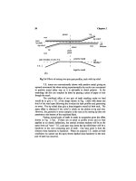
2.3
Unloaded T.E.
for
spur
gears
Fig.
2.6 (a)
shows
diagrammatically
what happens when
we
take
two
mating spur gear teeth, each with
tip
relief extending
a
third
of the way
down
(but
no
root relief),
and
mesh them.
All
distances along
the
profile
are
in
terms
of
roll distance,
not
actual distance,
and so are
proportional
to
gear
rotation
(multiplied
by
base circle radius).
The
horizontal line
represents
the
pure involute
and the two
tooth
profiles,
shown slightly apart
for
clarity,
follow
the
involute
profile
to
above
their pitch line where they
are
relieved.
In
this case
the tip
reliefs
are
linear,
as is
modern custom.
The
combination
of two
teeth with perfect involutes
in
the
centre
is to
give zero T.E.
for
this part
of the
mesh. Where there
is tip
relief
it is
irrelevant
which
gear
has it as
either gives
a
drop
in the
T.E. trace
for
the
combination.