Handbook of Corrosion Engineering Episode 1 Part 6 pdf
Bạn đang xem bản rút gọn của tài liệu. Xem và tải ngay bản đầy đủ của tài liệu tại đây (1.17 MB, 40 trang )
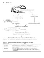
■
Fungi, which may produce corrosive by-products in their metabo-
lism, such as organic acids. Apart from metals and alloys, they can
degrade organic coatings and wood.
■
Slime formers, which may produce concentration corrosion cells on
surfaces.
A summary of the characteristics of bacteria commonly associated with
soil corrosion (mostly for iron-based alloys) is provided in Table 2.26.
2.4.4 Soil corrosivity classifications
For design and corrosion risk assessment purposes, it is desirable to
estimate the corrosivity of soils, without conducting exhaustive corrosion
testing. Corrosion testing in soils is complicated by the fact that long
exposure periods may be required (buried structures are usually expect-
ed to last for several decades) and that many different soil conditions can
be encountered. Considering the complexity of the parameters affecting
soil corrosion, it is obvious that the use of relatively simple soil corrosiv-
ity models is bound to be inaccurate. These limitations should be consid-
ered when applying any of the common aids/methodologies.
One of the simplest classifications is based on a single parameter, soil
resistivity. Table 2.27 shows the generally adopted corrosion severity
ratings. Sandy soils are high on the resistivity scale and therefore are
considered to be the least corrosive. Clay soils, especially those contam-
inated with saline water, are on the opposite end of the spectrum. The
soil resistivity parameter is very widely used in practice and is general-
ly considered to be the dominant variable in the absence of microbial
activity.
The American Water Works Association (AWWA) has developed a
numerical soil corrosivity scale that is applicable to cast iron alloys. A
severity ranking is generated by assigning points for different vari-
ables, presented in Table 2.28.
44
When the total points of a soil in the
AWWA scale are 10 (or higher), corrosion protective measures (such as
cathodic protection) have been recommended for cast iron alloys. It
should be appreciated that this rating scale remains a relatively sim-
plistic, subjective procedure for specific alloys. Therefore, it should be
viewed as a broad indicator and should not be expected to accurately
predict specific cases of corrosion damage.
A worksheet for estimating the probability of corrosion damage to
metallic structures in soils has been published, based on European
work in this field. The worksheet consists of 12 individual ratings (R1
to R12), listed in Table 2.29.
45
This methodology is very detailed and
comprehensive. For example, the effects of vertical and horizontal soil
homogeneity are included, as outlined in Table 2.30. Even details such
as the presence of coal or coke and other pollutants in the soil are con-
148 Chapter Two
0765162_Ch02_Roberge 9/1/99 4:02 Page 148
TABLE 2.26 Characteristics of Bacteria Commonly Associated with Corrosion in Soils
Species Likely soil conditions Metabolic action Species produced Comments
Sulfate-reducing Anaerobic, close to Convert sulfate Iron sulfide, Very well known for corrosion of iron
bacteria (SRB) neutral pH values, to sulfide hydrogen and steel. Desulfovibrio genus
presence of sulfate ions. sulfide very widespread
Often associated with
waterlogged clay soils
Iron-oxidizing Acidic, aerobic Oxidize ferrous Sulfuric acid, Thiobacillus ferrooxidans
bacteria (IOB) ions to ferric ions iron sulfate is a well-known example
Sulfur-oxidizing Aerobic, acidic Oxidize sulfur and Sulfuric acid Thiobacillus genus is a common
bacteria (SOB) sulfide to form example
sulfuric acid
Iron bacteria (IB) Aerobic, close to Oxidize ferrous ions Magnetite Gallionella genus is an example.
neutral pH values to ferric ions Usually associated with deposit
and tubercle formation
149
0765162_Ch02_Roberge 9/1/99 4:02 Page 149
sidered. The assessment is directed at ferrous materials (steels, cast
irons, and high-alloy stainless steels), hot-dipped galvanized steel, and
copper and copper alloys. Summation of the individual ratings pro-
duces an overall corrosivity classification into one of the four cate-
gories listed in Table 2.31. It has been pointed out that sea or lake beds
cannot be assessed using this worksheet.
150 Chapter Two
TABLE 2.27 Corrosivity Ratings Based on Soil Resistivity
Soil resistivity, ⍀иcm Corrosivity rating
Ͼ 20,000 Essentially noncorrosive
10,000–20,000 Mildly corrosive
5000–10,000 Moderately corrosive
3000–5000 Corrosive
1000–3000 Highly corrosive
Ͻ 1000 Extremely corrosive
TABLE 2.28 Point System for Predicting Soil Corrosivity
According to the AWWA C-105 Standard
Soil parameter Assigned points
Resistivity, ⍀иcm
Ͻ 700 10
700–1000 8
1000–1200 5
1200–1500 2
1500–2000 1
Ͼ 2000 0
pH
0–2 5
2–4 3
4–6.5 0
6.5–7.5 0
7.5–8.5 0
Ͼ 8.5 3
Redox potential, mV
Ͼ 100 0
50–100 3.5
0–50 4
Ͻ 05
Sulfides
Positive 3.5
Trace 2
Negative 0
Moisture
Poor drainage, continuously wet 2
Fair drainage, generally moist 1
Good drainage, generally dry 0
0765162_Ch02_Roberge 9/1/99 4:02 Page 150
2.4.5 Corrosion characteristics of selected
metals and alloys
Ferrous alloys.
Steels are widely used in soil, but almost never with-
out additional corrosion protection. It may come as something of a sur-
prise that unprotected steel is very vulnerable to localized corrosion
Environments 151
TABLE 2.30 R10 and R12 Worksheet Ratings
Resistivity variation between adjacent domains
(all positive R2 values are treated as equal) Rating
R10, Horizontal Soil Homogeneity
R2 difference Ͻ20
R2 difference Ն2 and Յ3 Ϫ2
R2 difference Ͼ3 Ϫ4
R11, Vertical Soil Homogeneity
Adjacent soils with same Embedded in soils with same 0
resistivity structure or in sand
Embedded in soils with
different structure or
containing foreign matter Ϫ6
Adjacent soils with R2 difference Ն2 and Յ3 Ϫ1
different resistivity R2 difference Ͼ3 Ϫ6
TABLE 2.29 Variables Considered in Worksheet
of Soil Corrosivity
Rating number Parameter
R1 Soil type
R2 Resistivity
R3 Water content
R4 pH
R5 Buffering capacity
R6 Sulfides
R7 Neutral salts
R8 Sulfates
R9 Groundwater
R10 Horizontal homogeneity
R11 Vertical homogeneity
R12 Electrode potential
TABLE 2.31 Overall Soil Corrosivity Classification
Summation of R1 to R12 ratings Soil classification
Ն0 Virtually noncorrosive
Ϫ1 to Ϫ4 Slightly corrosive
Ϫ5 to Ϫ10 Corrosive
Յ10 Highly corrosive
0765162_Ch02_Roberge 9/1/99 4:02 Page 151
damage (pitting) when buried in soil. Such attack is usually the result
of differential aeration cells, contact with different types of soil, MIC,
or galvanic cells when coal or cinder particles come into contact with
buried steel. Stray current flow in soils can also lead to severe pitting
attack. A low degree of soil aeration will not necessarily guarantee low
corrosion rates for steel, as certain microorganisms associated with
severe MIC damage thrive under anaerobic conditions.
The primary form of corrosion protection for steel buried in soil is
the application of coatings. When such coatings represent a physical
barrier to the environment, cathodic protection in the form of sacrifi-
cial anodes or impressed current systems is usually applied as an addi-
tional precaution. This additional measure is required because coating
defects and discontinuities will inevitably be present in protective
coatings.
Cast iron alloys have been widely used in soil; many gas and water
distribution pipes in cities are still in use after decades of service. These
have been gradually replaced with steel (coated and cathodically pro-
tected) and also with polymeric pipes. While cast irons are generally
considered to be more resistant to soil corrosion than steel, they are
subject to corrosion damage similar to that described above for steel.
Coatings and cathodic protection with sacrificial anodes tend to be used
to protect buried cast iron structures.
Stainless steels are rarely used in soil applications, as their corro-
sion performance in soil is generally poor. Localized corrosion attack is
a particularly serious concern. The presence of halide ions and con-
centration cells developed on the surface of these alloys tends to induce
localized corrosion damage. Since pitting tends to be initiated at rela-
tively high corrosion potential values, higher redox potentials increase
the localized corrosion risk. Common grades of stainless steel (even
the very highly alloyed versions) are certainly not immune to MIC,
such as attack induced by sulfate-reducing bacteria.
Nonferrous metals and alloys. In general, copper is considered to have
good resistance to corrosion in soils. Corrosion concerns are mainly
related to highly acidic soils and the presence of carbonaceous contam-
inants such as cinder. Chlorides and sulfides also increase the risk of
corrosion damage. Contrary to common belief, copper and its alloys are
not immune to MIC. Cathodic depolarization, selective leaching,
underdeposit corrosion, and differential aeration cells have been cited
as MIC mechanisms for copper alloys.
46
Corrosive products produced
by microbes include carbon dioxide, hydrogen sulfide and other sulfur
compounds, ammonia, and acids (organic and inorganic).
In the case of brasses, consideration must be given to the risk of
dezincification, especially at high zinc levels. Soils contaminated with
152 Chapter Two
0765162_Ch02_Roberge 9/1/99 4:02 Page 152
detergent solutions and ammonia also pose a higher corrosion risk for
copper and copper alloys. Additional corrosion protection for copper
and copper alloys is usually considered only in highly corrosive soil
conditions. Cathodic protection, the use of acid-neutralizing backfill
(for example, limestone), and protective coatings can be utilized.
The main application of zinc in buried applications is in galvanized
steel. Performance is usually satisfactory unless soils are poorly aerated,
acidic, or highly contaminated with chlorides, sulfides, and other solutes.
Well-drained soils with a coarse texture (the sandy type) provide a high
degree of aeration. It should also be borne in mind that zinc corrodes
rapidly under highly alkaline conditions. Such conditions can arise on
the surface of cathodically overprotected structures. The degree of corro-
sion protection afforded by galvanizing obviously increases with the
thickness of the galvanized coating. Additional protection can be afford-
ed by so-called duplex systems, in which additional paint coatings are
applied to galvanized steel.
The corrosion resistance of lead and lead alloys in soils is generally
regarded as being in between those of steel and copper. The corrosion
resistance of buried lead sheathing for power and communication
cables has usually been satisfactory. Caution needs to be exercised in
soils containing nitrates and organic acids (such as acetic acid).
Excessive corrosion is also found under highly alkaline soil conditions.
Silicates, carbonates, and sulfates tend to retard corrosion reactions by
their passivating effects on lead. Barrier coatings can be used as addi-
tional protection. When cathodic protection is applied, overprotection
should be avoided because of the formation of surface alkalinity.
Aluminum alloys are used relatively rarely in buried applications,
although some pipelines and underground tanks have been construct-
ed from these alloys. Like stainless steels, these alloys tend to under-
go localized corrosion damage in chloride-contaminated soils.
Protection by coatings is essential to prevent localized corrosion dam-
age. Cathodic protection criteria for aluminum alloys to minimize the
risk of generating undesirable alkalinity are available. Aluminum
alloys can undergo accelerated attack under the influence of microbio-
logical effects. Documented mechanisms include attack by organic acid
produced by bacteria and fungi and the formation of differential aera-
tion cells.
46
It is difficult to predict the corrosion performance of alu-
minum and its alloys in soils with any degree of confidence.
Reinforced concrete. Steel-reinforced concrete (SRC) pipes are widely
used in buried applications to transport water and sewage, and their
use dates back nearly a century. So-called prestressed concrete cylin-
der pipes (PCCP) were already developed prior to 1940 for designs
requiring relatively high operating pressures and large diameters.
Environments 153
0765162_Ch02_Roberge 9/1/99 4:02 Page 153
PCCP applications include water transmission mains, distribution
feeder mains, water intake and discharge lines, low-head penstocks,
industrial pressure lines, sewer force mains, gravity sewer lines, sub-
aqueous lines, and spillway conduits.
47
There are three dominant species in soils that lead to excessive
degradation of reinforced concrete piping. Sulfate ions tend to attack
the tricalcium aluminate phase in concrete, leading to severe degra-
dation of the concrete/mortar cover and exposure of the reinforcing
steel. The mechanism of degradation involves the formation of a volu-
minous reaction product in the mortar, which leads to internal pres-
sure buildup and subsequent disintegration of the cover. Sulfate levels
exceeding about 2 percent (by weight) in soils and groundwater report-
edly put concrete pipes at risk. Chloride ions are also harmful, as they
tend to diffuse into the concrete and lead to corrosion damage to the
reinforcing steel. A common source of chloride ions is soil contamina-
tion by deicing salts. This corrosion phenomenon is discussed in detail
in Sec. 2.5, Reinforced Concrete. Finally, acidic soils present a corro-
sion hazard. The protective alkaline environment that passivates the
reinforcing steel can be disrupted over time. Carbonic acid and humic
acid are examples of acidic soil species.
2.4.6 Summary
Corrosion processes in soil are highly complex phenomena, especially
since microbiologically influenced corrosion can play a major role. Soil
parameters tend to vary in three dimensions, which has important
ramifications for corrosion damage. Such variations tend to set up
macrocells, leading to accelerated corrosion at the anodic site(s). The
corrosion behavior of metals and alloys in other environments should
not be extrapolated to their performance in soil. In general, soils rep-
resent highly corrosive environments, often necessitating the use of
additional corrosion protection measures for common engineering met-
als and alloys.
2.5 Reinforced Concrete
2.5.1 Introduction
Concrete is the most widely produced material on earth. The use of
cement, a key ingredient of concrete, by Egyptians dates back more
than 3500 years. In the construction of the pyramids, an early form of
mortar was used as a structural binding agent. The Roman Coliseum
is a further example of a historic landmark utilizing cement mortar as
a construction material. Worldwide consumption of concrete is close to
9 billion tons and is expected to rise even further.
154 Chapter Two
0765162_Ch02_Roberge 9/1/99 4:02 Page 154
Contrary to common belief, concrete itself is a complex composite
material. It has low strength when loaded in tension, and hence it is
common practice to reinforce concrete with steel, for improved tensile
mechanical properties. Concrete structures such as bridges, buildings,
elevated highways, tunnels, parking garages, offshore oil platforms,
piers, and dam walls all contain reinforcing steel (rebar). The princi-
pal cause of degradation of steel-reinforced structures is corrosion
damage to the rebar embedded in the concrete. The scale of this prob-
lem has reached alarming proportions in various parts of the world. In
the early 1990s, the costs of rebar corrosion in the United States alone
were estimated at $150 to $200 billion per year.
48
The durability of concrete should not simply be equated to high-
strength grades of concrete. There are several methods for controlling
rebar corrosion in new structures, and valuable lessons can be learned
from previous failures. In existing structures, the choices for correct-
ing rebar corrosion problems are relatively limited. The corrosion
mechanisms involved in the repair of existing structures may be fun-
damentally different from those that affect new constructions. A
gamut of inspection methods is available for assessment of the condi-
tion of reinforced concrete structures.
2.5.2 Concrete as a structural material
In order to understand corrosion damage in concrete, a basic under-
standing of the nature of concrete as an engineering material is
required. A brief summary follows for this purpose. It is important to
distinguish clearly among terms such as cement, mortar, and concrete.
Unfortunately, these tend to be used interchangeably in household use.
The fundamental ingredients required to make concrete are cement
clinker, water, fine aggregate, coarse aggregate, and certain special addi-
tives. Cement clinker is essentially a mixture of several anhydrous
oxides. For example, standard Portland cement consists mainly of the
following compounds, in order of decreasing weight percent: 3CaOиSiO
2
,
2CaOиSiO
2
, 3CaOиAl
2
O
3
, and 4CaOиAl
2
O
3
иFe
2
O
3
. The cement reacts with
water to form the so-called cement paste. It is the cement paste that sur-
rounds the coarse and fine aggregate particles and holds the material
together. The importance of adequately mixing the concrete constituents
should thus be readily apparent. The fine and coarse aggregates are
essentially inert constituents. In general, the size of suitable aggregate
is reduced as the thickness of the section of a structure decreases.
The reaction of the cement and water to form the cement paste is
actually a series of complex hydration reactions, producing a multi-
phase cement paste. One example of a specific hydration reaction is
the following:
Environments 155
0765162_Ch02_Roberge 9/1/99 4:02 Page 155
2(3CaO и SiO
2
) ϩ 6H
2
O → 3Ca(OH)
2
ϩ 3CaO и 2SiO
2
и 3H
2
O (2.28)
Following the addition of water, the cement paste develops a fibrous
microstructure over time. Importantly for corrosion considerations,
the cement paste is not a continuous solid material on a microscopic
scale. Rather, the cement paste is classified as a “gel” to describe its
limited crystalline character and the water-filled spaces between the
solid phases. These microscopic spaces are also known as gel “pores”
and, strictly speaking, are filled with an ionic solution rather than
“water.” Additional pores of larger size are found in the cement paste
and between the cement paste and the aggregate particles. The pores
that result from excess water in the concrete mix are known as capil-
lary pores. Air voids are also invariably present in concrete. In so-
called air-entrained concrete, microscopic air voids are intentionally
created through admixtures. This practice is widely used in cold cli-
mates to minimize freeze-thaw damage. Clearly then, concrete is a
porous material, and it is this porosity that allows the ingress of cor-
rosive species to the embedded reinforcing steel.
A further important feature of the hydration reactions of cement with
water is that the resulting pore solution in concrete is highly alkaline
[refer to Eq. (2.28) above]. In addition to calcium hydroxide, sodium and
potassium hydroxide species are also formed, resulting in a pH of the
aqueous phase in concrete that is typically between 12.5 and 13.6.
Under such alkaline conditions, reinforcing steel tends to display com-
pletely passive behavior, as fundamentally predicted by the Pourbaix
diagram for iron. In the absence of corrosive species penetrating into
the concrete, ordinary carbon steel reinforcing thus displays excellent
corrosion resistance.
From the above discussion, the complex nature of concrete as a par-
ticulate-strengthened ceramic-matrix composite material and the dif-
ference between the terms concrete and cement should be apparent.
The term mortar refers to a concrete mix without the addition of any
coarse aggregate.
2.5.3 Corrosion damage in reinforced
concrete
Mehta’s holistic model of concrete degradation.
The large-scale environ-
mental degradation of the reinforced concrete infrastructure in many
countries (often prematurely) has indicated that traditional approach-
es to concrete durability may be in need of revision. Historically, the
general approach has been to relate concrete durability directly to the
strength of concrete. It is well known that higher water-to-cement
ratios in concrete lead to lower strength and increase the degree of
156 Chapter Two
0765162_Ch02_Roberge 9/1/99 4:02 Page 156
porosity in the concrete. A generally accepted argument is that low-
strength, more permeable concrete is less durable. However, in real
reinforced concrete structures, durability issues are more complex,
and consideration of the strength variable alone is inadequate.
The approach adopted by Mehta in his holistic model of concrete degra-
dation was to focus on the soundness of concrete under service conditions
as a fundamental measure of concrete durability rather than on the
strength of concrete. In simplistic terms, soundness of concrete implies
freedom from cracking.
49
Mehta’s proposed model of concrete degradation
has been adapted in the illustration of environmental damage in Fig.
2.25. According to this model, concrete manufactured to high quality stan-
dards is initially considered to be an impermeable structure. This condi-
tion exists so long as interior pores and microcracks do not form
interconnected paths extending to the exterior surfaces.
Under environmental weathering and loading effects, the perme-
ability of the concrete gradually increases as the network of “defects”
becomes more interconnected over time. It is then that water, carbon
dioxide, and corrosive ions such as chlorides can enter the concrete
and produce detrimental effects at the level of the reinforcing steel.
The corrosion mechanisms involved are discussed in more detail in
subsequent sections. The buildup of corrosion products leads to a
buildup of internal pressure in the reinforced concrete because of the
voluminous nature of these products. The volume of oxides and
hydroxides associated with rebar corrosion damage relative to steel is
shown in Fig. 2.26. In turn, these internal stresses lead to severe
cracking and spalling of the concrete covering the reinforcing steel.
Extensive surface damage produced in this manner is shown in Figs.
2.27 and 2.28. It is clear that the damage inflicted by formation of cor-
rosion products (and other effects) reduces the soundness of concrete
and facilitates further deterioration at an increasing rate.
In the light of the importance that Mehta’s model of environmental
concrete degradation attaches to defects such as cracks, the reliance on
the high strength of concrete alone for satisfactory service life becomes
questionable. High strength levels in concrete alone certainly do not
guarantee a high degree of soundness; several arguments can be made
for high-strength concrete being potentially more prone to cracking.
The importance of concrete cracks in rebar corrosion has also been
highlighted by Nürnberger.
50
Both carbonation and chloride ion diffu-
sion, two important processes associated with rebar corrosion, can pro-
ceed more rapidly into the concrete along the crack faces, compared
with uncracked concrete. Nürnberger argued that corrosion in the
vicinity of the crack tip could be accelerated further by crevice corro-
sion effects and galvanic cell formation. The steel in the crack will tend
to be anodic relative to the cathodic (passive) zones in uncracked
Environments 157
0765162_Ch02_Roberge 9/1/99 4:02 Page 157
158 Chapter Two
A “new” reinforced concrete structure containing
discontinuous cracks, microcracks and pores
Cracks, microcracks and pores become more interconnected
Serious cracking, spalling and loss of mass
Expansion of concrete due to internal pressure buildup
caused by corrosion of steel, freezing water and
chemical attack of the concrete
Reduction in strength and stiffness of concrete
CLOSED
Environmental Effect:
Cyclic heating, cooling
Wetting/drying
Cyclic and impact loading
Stage 1:
No visible damage
Stage 2:
Initiation and
propagation of damage
Environmental Effect:
Penetration of corrosive
species
Penetration of water
Figure 2.25 Concrete degradation processes resulting from environmental effects.
0765162_Ch02_Roberge 9/1/99 4:02 Page 158
concrete. The particularly harmful effects of dried-out cracks (as
opposed to those that are water-filled), which allow rapid ingress of
corrosive species, were also emphasized. Even casual visual examina-
tions of most reinforced concrete structures invariably reveal the pres-
ence of macroscopic cracks in concrete.
Corrosion mechanisms. The two most common mechanisms of reinforc-
ing steel corrosion damage in concrete are (1) localized breakdown of the
passive film by chloride ions and (2) carbonation, a decrease in pore solu-
tion pH, leading to a general breakdown in passivity. Harmful chloride
ions usually originate from deicing salts applied in cold climate regions
or from marine environments/atmospheres. Carbonation damage is pre-
dominantly induced by a reaction of concrete with carbon dioxide (CO
2
)
in the atmosphere.
Chloride-induced rebar corrosion. Corrosion damage to reinforcing
steel is an electrochemical process with anodic and cathodic half-cell
reactions. In the absence of chloride ions, the anodic dissolution reac-
tion of iron,
Environments 159
Relative
Volume
Fe
FeO
Fe O
34
Fe O
23
Fe(OH)
2
Fe(OH)
3
Fe(OH) .3H O
32
Figure 2.26 Relative volume of possible rebar corrosion products.
0765162_Ch02_Roberge 9/1/99 4:02 Page 159
160 Chapter Two
Figure 2.27 Concrete degradation caused by rebar corrosion damage in a highway structure
in downtown Toronto, Ontario. Extensive repair work was underway on this structure at
the time the picture was taken. The annual maintenance costs for this structure were
recently reported at around $18 million.
0765162_Ch02_Roberge 9/1/99 4:02 Page 160
Environments 161
Figure 2.28 Concrete degradation caused by rebar corrosion damage near
Kingston, Ontario. This bridge underwent extensive rehabilitation shortly
after this picture was taken.
0765162_Ch02_Roberge 9/1/99 4:02 Page 161
Fe → Fe
2ϩ
ϩ 2e
Ϫ
(2.29)
is balanced by the cathodic oxygen reduction reaction,
1
ր
2
O
2
ϩ H
2
O ϩ 2e
Ϫ
→ 2OH
Ϫ
(2.30)
Oxygen diffuses to the reinforcing steel surface through the porous
concrete, with cracks acting as fast diffusion paths, especially if they
are not filled with water. The Fe
2ϩ
ions produced at the anodes com-
bine with the OH
Ϫ
ions from the cathodic reaction to ultimately pro-
duce a stable passive film. This electrochemical process is illustrated
schematically in Fig. 2.29.
Chloride ions in the pore solution, having the same charge as OH
Ϫ
ions, compete with these anions to combine with the Fe
2ϩ
cations. The
resulting iron chloride complexes are thought to be soluble (unstable);
therefore, further metal dissolution is not prevented, and ultimately
the buildup of voluminous corrosion products takes place. Chloride
ions also tend to be released from the unstable iron chloride complex-
es, making these harmful ions available for further reaction with the
reinforcing steel. As the iron ultimately precipitates out in the form of
iron oxide or hydroxide corrosion products, it can be argued that the
consumption of hydroxide ions leads to localized pH reduction and
therefore enhanced metal dissolution.
162 Chapter Two
HO2
O2
O2
O2
O 2
Fe
2e
-
2+
Anode Reaction : Fe Fe + 2e
Cathode Reaction: 1/2O + H O + 2e 2OH
2
2
-
-
-
2+
Oxygen diffuses into
the Concrete
The Pore Solution acts
as the Electrolyte
Depth
of Cover
Figure 2.29 Schematic illustration of electrochemical corrosion reactions in concrete.
0765162_Ch02_Roberge 9/1/99 4:02 Page 162
Chloride-induced rebar corrosion tends to be a localized corrosion
process, with the original passive surface being destroyed locally
under the influence of chloride ions. Apart from the internal stresses
created by the formation of corrosion products leading to cracking and
spalling of the concrete cover, chloride attack ultimately reduces the
cross section and significantly compromises the load-carrying capabil-
ity of steel-reinforced concrete.
Sources of chloride ions and diffusion into concrete. The harmful chloride
ions leading to rebar corrosion damage either originate directly from
the concrete mix constituents or diffuse into the concrete from the sur-
rounding environment. The use of seawater or aggregate that has been
exposed to saline water (such as beach sand) in concrete mixes creates
the former case. Calcium chloride has been deliberately added to cer-
tain concrete mixes to accelerate hardening at low temperatures,
mainly before the harmful corrosion effects were widely known.
An important source of chlorides from the external environment is
the widespread use of deicing salts on road surfaces in cold climates.
Around 10 million tons of deicing salt is used annually in the United
States; the Canadian figure is about 3 million tons. The actual tonnage
used each year fluctuates with the severity of the particular winter
season. The main purpose of deicing salt application is to keep road-
ways safe and passable in winter and to minimize the disruption of
economic activity. The application of salt to ice and snow results in the
formation of brine, which has a lower freezing point.
Salt, primarily in the form of rock salt, is the most widely used deic-
ing agent in North America because of its low cost, general availabili-
ty, and ease of storage and handling. Rock salt is also known as halite
and has the well-known chemical formula NaCl. The rate of salt appli-
cation to roads varies with traffic and weather conditions. Other chlo-
ride compounds in use for deicing purposes are calcium chloride
(CaCl
2
) and magnesium chloride (MgCl
2
).
Other obvious important sources of corrosive chloride ions are sea-
water and marine atmospheres. Alternate drying and wetting cycles
promote the buildup of chloride ions on surfaces. Hence actual surface
concentrations of chlorides can be well in excess of those of the bulk
environment.
Clearly the diffusion rate of external chlorides into concrete to the
reinforcing steel is very important. While some simplified models such
as Fick’s second law of diffusion have been used for life prediction pur-
poses in combination with so-called critical chloride levels, the actual
processes are much more complex than such simplistic models.
Considering the complex nature of concrete as a material on the
microstructural scale, this complexity must be anticipated. Chloride
Environments 163
0765162_Ch02_Roberge 9/1/99 4:02 Page 163
diffusion processes are affected by capillary suction and chemical and
physical interaction in the concrete. Weather/climatic conditions, the
pore structure in concrete, and other microstructural parameters are
important variables. If only the capillary suction mechanism is con-
sidered, the rate of chloride ingress from exposure to a saline solution
will be higher in dry concrete than in water-saturated concrete.
Furthermore, the surface concentration of chlorides is obviously time-
dependent, particularly in deicing salt applications, adding more com-
plications to diffusion models. The effects of cracks on both the
macroscopic and microscopic levels are also important practical con-
siderations, since they function as rapid chloride diffusion paths.
Chlorides in concrete and critical chloride levels. Chlorides in concrete exist in
two basic forms, so-called free chlorides and bound chlorides. The former
are mobile chlorides dissolved in the pore solution, whereas the latter
type represents relatively immobile chloride ions that interact (by chem-
ical binding and/or adsorption) with the cement paste. At first glance, it
may appear that only the free chlorides should be considered for corro-
sion reactions. However, Glass and Buenfeld have recently reviewed the
role of both bound and free chlorides in corrosion processes in detail and
have concluded that both types may be important.
51
Bound chloride may
essentially buffer the chloride ion activity at a high value, and localized
acidification at anodic sites may release some bound chloride.
The determination of a critical chloride level, below which serious
rebar corrosion damage does not occur, for design, maintenance plan-
ning, and life prediction purposes is appealing. Not surprisingly, then,
several studies have been directed at defining such a parameter.
Unfortunately, the concept of a critical chloride content as a universal
parameter is unrealistic. Rather, a critical chloride level should be
defined only in combination with a host of other parameters. After all,
a threshold chloride level for corrosion damage will be influenced by
variables such as
■
The pore solution pH
■
Moisture content of the concrete
■
Temperature
■
Age and curing conditions of the concrete
■
Water-to-cement ratio
■
Pore structure and other “defects”
■
Oxygen availability (hence cover and density of concrete)
■
Presence of prestressing
■
Cement and concrete composition
164 Chapter Two
0765162_Ch02_Roberge 9/1/99 4:02 Page 164
Considering the above, it is apparent that the specification of critical
chloride levels should be treated with extreme caution. Furthermore, it
should not be surprising that an analysis of 15 chloride levels reported
for the initiation of corrosion of steel produced a range of 0.17 to 2.5
percent, expressed as total chlorides per weight of cement.
51
Carbonation-induced corrosion. Carbon dioxide present in the atmos-
phere can reduce the pore solution pH significantly by reacting with
calcium hydroxide (and other hydroxides) to produce insoluble carbon-
ate in the concrete as follows:
Ca(OH)
2
ϩ CO
2
→ CaCO
3
ϩ H
2
O (2.31)
Carbonation is manifested as a reduction in the pH of the pore solu-
tion in the outer layers of the concrete and often appears as a well-
defined “front” parallel to the external surface. This front can
conveniently be made visible by applying a phenolphthalein indicator
solution to freshly exposed concrete surfaces. Behind the front, where
all the calcium hydroxide has been depleted, the pH is around 8, where-
as ahead of the front, the pH remains in excess of 12.5.
52
The passivat-
ing ability of the pore solution diminishes with the decrease in pH.
Carbonation-induced corrosion tends to proceed in a more uniform man-
ner over the rebar surface than chloride-induced corrosion damage.
The rate of ingress of carbonation damage in concrete decreases
with time. Obviously carbon dioxide has to penetrate greater distances
into the concrete over time. The precipitation of calcium carbonate and
possibly additional cement hydration are also thought to contribute to
the reduced rate of ingress.
52
Several variables affect the rate of carbonation. In general, low-per-
meability concrete is more resistant. Carbonation tends to proceed
most rapidly at relative humidity levels between 50 and 75 percent. At
lower humidity levels, carbon dioxide can penetrate into the concrete
relatively rapidly, but little calcium hydroxide is available in the dis-
solved state for reaction with it. At higher humidity levels, the water-
filled pore structure is a more effective barrier to the ingress of carbon
dioxide. Clearly, environmental cycles of alternate dry and wet condi-
tions will be associated with rapid carbonation damage.
In many practical situations, carbonation- and chloride-induced
corrosion can occur in tandem. Research studies have shown that cor-
rosion caused by carbonation was intensified with increasing chloride
ion concentration, provided that the carbonation rate itself was not
retarded by the presence of chlorides.
52
According to these studies,
chloride attack and carbonation can act synergistically (the combined
damage being more severe than the sum of its parts) and have been
responsible for major corrosion problems in hot coastal areas.
Environments 165
0765162_Ch02_Roberge 9/1/99 4:02 Page 165
2.5.4 Remedial measures
In principle, a number of fundamental technical measures can be tak-
en to address the problem of reinforcing steel corrosion, such as
■
Repairing the damaged concrete
■
Modifying the external environment
■
Modifying the internal concrete environment
■
Creating a barrier between the concrete and the external environment
■
Creating a barrier between the rebar steel and the internal concrete
environment
■
Applying cathodic protection to the rebar
■
Using alternative, more corrosion-resistant rebar materials
■
Using alternative methods of reinforcement
Alternative solutions to periodic repair of damaged concrete are
being sought. After all, this is generally a costly corrective mainte-
nance approach after serious damage has already set in. In view of the
overwhelming magnitude of the problem and increasingly limited gov-
ernment budgets, various alternative approaches have come to the
forefront over the last two decades. Several of these are still in emerg-
ing stages with limited track records. Given that rebar corrosion prob-
lems are typically manifested only over many decades, it takes
significant time for new technologies to acquire credibility in industri-
al practice.
An important distinction has to be made in the applicability of reme-
dial measures to new and existing structures. Unfortunately, the
options for the most pressing problems in aging existing structures are
fairly limited. Obviously even the “best” technologies for new con-
struction are of limited value if education and technology transfer
efforts directed at designers and users are not effective. This aspect is
particularly challenging in the fragmented construction industry.
52
A
further important prerequisite for advancing the cause of effective cor-
rosion control in reinforced concrete structures is acceptance and
implementation of life-cycle costing, as opposed to awarding contracts
on the basis of the lowest initial capital cost outlay.
Alternative deicing methods. Since chloride-based deicing agents are a
major factor in rebar corrosion, one obvious consideration is the possi-
ble use of alternative noncorrosive deicing chemicals. Such chemicals
are indeed available and are used in selective applications, such as for
airport runway deicing and on certain bridges. In addition to the cor-
rosive action on reinforcing steel, the details of the deicing mechanism
166 Chapter Two
0765162_Ch02_Roberge 9/1/99 4:02 Page 166
(temperature ranges, texture of products, etc.) and possible damage to
the concrete itself obviously need to be considered for alternative chem-
icals. Strictly speaking, a distinction is also made between anti-icing
and deicing, depending on whether chemical application is done before
or after snow and ice accumulation. An excellent summary of highway
deicing practices has been published by the Ministry of Transportation,
Ontario.
53
The potential use of calcium magnesium acetate (CMA) has been
extensively researched in North America, and field trials have
been conducted in several states and provinces. The CMA specifica-
tion in terms of composition, particle size and shape, color, and den-
sity has evolved over time. CMA application rates have generally
been higher than those for salt. The majority of trials conducted
have indicated effectiveness similar to that of salt at temperatures
down to Ϫ5°C, but slower performance than salt at lower tempera-
tures. Unfortunately, costs are reportedly more than 10 times high-
er than those of road salt on a mass basis. If a higher application
rate of 1.5 times that of salt is assumed, a cost factor increase of 45
has been reported.
53
Cost issues surrounding the use of CMA are
complex and include factors such as potential environmental bene-
fits, reduced automobile corrosion, mass production technology, and
alternative raw materials.
The use of formate compounds as highway deicers was explored as
early as 1965. Lower reaction rates of sodium formate with snow and
ice have been reported in Canadian field trials. In the Canadian stud-
ies, commercial grades of sodium formate were found to be “contami-
nated” with chlorides.
53
Concerns related to automobile corrosion and
increased costs have been expressed, and little information is avail-
able concerning possible adverse effects on the environment.
Urea is widely used as an airport runway deicer, as it is not corro-
sive to aircraft materials. However, urea is generally not considered to
be a viable alternative deicing chemical for highway applications.
Reported limitations include higher application rates, longer reaction
times, effectiveness only at temperatures above Ϫ10°C, relatively high
cost, and significant adverse effects on the environment.
53
Verglimit, a patented compound, is often mentioned in the context
of alternative deicing compounds. In this product, capsules that con-
tain calcium chloride are incorporated into asphalt paving. With grad-
ual wear and tear of the asphalt surface, the capsules are exposed and
broken open, releasing the deicing chemical. This methodology was
specifically designed for exposed bridge decks that freeze over more
rapidly than adjacent road surfaces. Many North American readers
will be familiar with the traffic warning signs, “Caution: Bridge
Freezes First.”
Environments 167
0765162_Ch02_Roberge 9/1/99 4:02 Page 167
Abrasives are widely used in Europe and North America to improve
skid resistance, and using them exclusively as a means of eliminating
deicing salts has been considered. While mixtures of sand and road
salt are widely used, elimination of deicing chemicals has not proved
feasible in geographic areas such as Ontario. A major problem is that
abrasives alone do not assist snowplows in removing ice bonded to
pavements. Other problems include the blocking of storm sewers and
accumulation in catch basins. Importantly, without mixed-in deicing
chemicals, stockpiles of abrasives would tend to freeze in winter, with
resultant reduced workability and difficulty in spreading. Such stock-
piles invariably contain moisture, causing abrasive particles to freeze
together in winter.
The concept of embedding electrical heating elements in concrete to
keep road surfaces ice-free has received some attention. Considering
the fact that electric power is routinely fed to street lighting, the
potential merits of such systems can be appreciated. A Canadian
experimental concept of electrically conducting concrete also appears
to hold promise for heating purposes. Other innovative experimental
approaches that have been explored include noncontact deicing with
acoustic or microwave energy.
Alternative deicing methods are largely applicable to new structures;
arguably, they may also benefit existing structures, provided that no
serious corrosion damage or chloride ion ingress has taken place.
Cathodic protection. Cathodic protection (CP) is one of the few tech-
niques that can be applied to control corrosion on existing structures.
Cathodic protection of conventional rebar is well established, with
applications dating back well over 20 years. The subject of the applica-
bility of CP to prestressed concrete (pre- and posttensioned systems) is
much more controversial, with the main concern being hydrogen
embrittlement of the high-strength prestressing steel. To the author’s
knowledge, CP for prestressed concrete has not progressed beyond ini-
tial laboratory tests. The difficult issues surrounding CP and pre-
stressed concrete have been reviewed by Hartt.
54
The principles and theory of cathodic protection are the subject of
Chap. 11. Essentially the concept involves polarizing the rebar to a
cathodic potential, where anodic dissolution of the rebar is minimized.
A direct current source (rectifier) is usually employed to establish the
rebar as the cathode of an electrochemical cell, and a separate anode
is required to complete the electric circuit. Three basic methods are
available for controlling the output of a rectifier:
■
In constant-current mode, the rectifier maintains a constant current
output. The output voltage will vary with changes in the circuit
168 Chapter Two
0765162_Ch02_Roberge 9/1/99 4:02 Page 168
resistance. The potential of the reinforcing steel can be measured
with a reference cell as a function of the applied current, to ensure
that certain protection criteria are met.
■
In constant-voltage mode, a constant output voltage is maintained by
the rectifier. The applied current will change with variations in cir-
cuit resistance. Low concrete resistance, often associated with
increased risk for corrosion damage, will result in increased current
output. It should be noted that in this mode, the rebar potential is not
necessarily constant. It can again be monitored with a reference cell.
■
In constant rebar potential mode, the current output is adjusted con-
tinuously to provide a constant (preselected) rebar potential. The
rebar potential, measured continuously with reference electrodes, is
fed back to the rectifier unit. Successful operation in this mode
depends on minimizing the IR drop error in the rebar potential mea-
surements and on the accuracy and stability of the reference elec-
trodes over time.
An important issue in CP of reinforcing steel is how much current
should be impressed between the reinforcing steel and the anode. Too
little current will result in inadequate corrosion protection of the
rebar, while excessive current can result in problems such as hydrogen
embrittlement and concrete degradation. Furthermore, a uniform cur-
rent distribution is obviously desirable.
Unfortunately, the current requirement cannot be measured directly,
and various indirect criteria have been proposed (see Table 2.32). The
CP current requirements are often expressed in terms of the potential
of the reinforcing steel (or a shift in the potential when the CP system
is activated or deactivated) relative to a reference electrode. The refer-
ence electrodes can be located externally, in contact with the outside
concrete surface, or be embedded in the concrete with the rebar. It is
important that potential readings should be free from so-called IR drop
errors; this fundamental aspect is discussed in more detail in Chap. 11.
The current densities involved in meeting commonly used protection
criteria are typically around 10 mA per square meter of rebar surface.
Adequate anode lifetime is obviously also an important factor relat-
ed to the magnitude and uniformity of current flow. A variety of anode
systems have evolved for cathodic protection of reinforcing steel, each
with certain advantages and limitations. Continuous surface anodes
have been based on conductive bituminous overlays and conductive
surface coatings. The former are suited only to horizontal surfaces. In
general, good current distribution is achievable with such systems.
Discrete anodes have been used without overlays and with cementi-
tious overlays. For horizontal surfaces, anodes without overlays can be
recessed in the concrete surface. Nonuniform current distribution is a
Environments 169
0765162_Ch02_Roberge 9/1/99 4:02 Page 169
fundamental concern in these systems. Anodes in the form of a titani-
um mesh, with proprietary surface coatings of precious metals, are
commonly used in concrete structures, in conjunction with cementi-
tious overlays. These systems are applicable to both horizontal and
vertical surfaces and generally provide uniform current distribution.
Although the underlying principle of cathodic protection is a rela-
tively simple one, considerable attention needs to be directed at details
such as sound electrical connections, reliable reference electrodes,
durable control cabinets, possible short circuits between the anodes
and rebar, and maintenance schedules for the CP hardware.
Electrochemical chloride extraction. A further technique, applicable to
existing concrete structures that have been contaminated with chlo-
rides, involves the electrochemical removal of these harmful ions. The
hardware involved is similar to that involved in cathodic protection.
Electrochemical extraction of chloride ions is achieved by establishing
170 Chapter Two
TABLE 2.32 Cathodic Protection Criteria for Steel in Concrete
Criterion Details Comments
Potential shift 100-mV shift of rebar Depolarization occurs when CP
potential in the positive current is switched off. Time
direction when system period required for rebar to
is depolarized. depolarize is debatable. The
potential reading before
interrupting the CP current
should be IR corrected.
Potential shift 300-mV shift of rebar The potential reading with the CP
potential in the negative current on should be IR corrected.
direction due to application The method relies on a stable
of CP current. rebar potential before the
application of CP current.
E log i curve The decrease in corrosion This methodology is
rate due to the application structure-specific, and the
of CP current can be measurements involved are
determined provided the relatively complex and require
relationship between rebar specialist interpretation. Ideal
potential E and current i can Tafel behavior is rarely observed
be measured and modeled. for steel in concrete.
A simple model is Tafel
behavior with a linear
relationship between E
and log i.
Current density Application of 10 mA/m
2
Empirical approach based on
of rebar surface area. limited experience. Does not
consider individual characteristics
of structures and environments.
0765162_Ch02_Roberge 9/1/99 4:02 Page 170
an anode and a caustic electrolyte on the external concrete surface,
and impressing a direct current between the anode and the reinforcing
steel, which acts as the cathode (Fig. 2.30). Under the application of
this electric field, chloride ions migrate away from the negatively
charged steel and toward the positively charged external anode.
Chloride extraction has been recommended for structures that do not
contain pre- or posttensioned steel and have little damage to the con-
crete itself. The current densities involved are significantly higher than
those used in cathodic protection. The unsuitability of the technique to
prestressed concrete is thus not surprising. The risk of hydrogen evo-
lution on the rebar and subsequent hydrogen embrittlement is clearly
much greater than in cathodic protection. Further requirements are a
high degree of rebar electrical continuity and preferably low concrete
resistance. Since the extraction processes require several days or even
weeks using suitable current densities, the technique is more applica-
ble to highway substructures than to bridge decks (most readers will
agree that long traffic closures are highly unpopular).
In practice, the chloride extraction process does not remove the
chloride ions from the concrete completely. Rather, a certain percent-
age is removed and the balance is redistributed away from the rein-
forcing bars. Importantly, through the cathodic reaction on the rebar
surface, OH
Ϫ
ions are generated, which have an important effect in
counteracting the harmful influence of chloride ions, as explained
earlier.
As with cathodic protection, the applied current density has to be
controlled. If the current magnitude is excessive, several problems can
arise, such as reduction in bond strength, softening of the cement paste
around the rebar steel, and cracking of the concrete. Concrete contain-
ing alkali-reactive aggregates is not considered a suitable candidate for
the process, as the expansive reactions leading to cracking and spalling
associated with these aggregates tend to be aggravated.
55
Electrochemical chloride extraction has been applied industrially for
a number of years and can be an effective control method for chloride-
induced corrosion of existing structures. Its limitations and drawbacks
must be recognized, and it is clear that it is a relatively complex
methodology, requiring specialized knowledge.
Re-alkalization. This treatment is applied to existing structures, to
restore alkalinity around reinforcing bars in previously carbonated con-
crete. The electrochemical principle and hardware are similar to those
for electrochemical chloride extraction. Direct current is applied
between the cathodic rebar and external anodes positioned at the exter-
nal concrete surface and surrounded by electrolyte (Fig. 2.30).
Compared to cathodic protection, the current densities in re-alkalization
Environments 171
0765162_Ch02_Roberge 9/1/99 4:02 Page 171
are again significantly higher. Typically, the process is applied for sev-
eral days to restore alkalinity in carbonated concrete.
The external electrolyte used in re-alkalization is a sodium carbonate
solution, with a caustic pH. In addition to the generation of hydroxyl
(OH
Ϫ
) ions at the cathode and their migration away from the rebar under
the electric field, other mechanisms can account for the formation of
alkaline solution in the concrete. First, simple diffusion effects may arise
as a result of concentration gradients in the concrete. Furthermore,
172 Chapter Two
Inner
blanket
Concrete
Rectifier
Rebar
(cathode)
Anode
mesh
Outer
blanket
Electrolyte in fibrous blankets
Ϫϩ
Figure 2.30 Principle of electrochemical chloride extraction and re-alkalization treat-
ments (schematic).
0765162_Ch02_Roberge 9/1/99 4:02 Page 172