Handbook of Corrosion Engineering Episode 1 Part 11 doc
Bạn đang xem bản rút gọn của tài liệu. Xem và tải ngay bản đầy đủ của tài liệu tại đây (564.18 KB, 33 trang )
In practice, materials used for their strength are the most suscepti-
ble to suffer from SCC problems when some environmental elements
render them vulnerable. Such vulnerability exists for stainless steels
when chloride ions are present in the environment, even at very low
concentrations. Unfortunately, the term stainless steel is sometimes
interpreted too literally. Structural engineers need to be aware that
stainless steels are certainly not immune to corrosion damage and can
be particularly susceptible to localized corrosion damage and SCC. The
austenitic stainless steels, mainly UNS S30400 and UNS S31600, are
used extensively in the construction industry. The development of SCC
in S30400 bars, on which a concrete ceiling was suspended in a swim-
ming pool building, had disastrous consequences.
In May 1985, the heavy ceiling in a swimming pool located in Uster,
Switzerland, collapsed with fatal consequences
14
after 13 years of ser-
vice. The failure mechanism was established to be transgranular SCC,
as illustrated in Fig. 5.16. The presence of a tensile stress was clearly
created in the stainless rods by the weight of the ceiling. Chloride
species dispersed into the atmosphere, together with thin moisture
films, in all likelihood represented the corrosive environment. A char-
acteristic macroscopic feature of the failed stainless steel rods was the
brittle nature of the SCC fractures, with essentially no ductility dis-
played by the material in this failure mode.
Subsequent to this failure, further similar incidents (fortunately
without fatalities) have been reported in the United Kingdom,
Germany, Denmark, and Sweden. Although chloride-induced SCC
damage is recognized as a common failure mechanism in stainless
steels, a somewhat surprising element of these failures is that they
occurred at room temperature. As a general rule of thumb, it has often
been assumed that chloride-induced SCC in these alloys is not a prac-
tical concern at temperatures below 60°C.
Under the assumption that a low-pH–high-chloride microenviron-
mental combination is responsible for the SCC failures, several factors
were identified in UK pool operations that could exacerbate the dam-
age. Notable operational changes included higher pool usage and pool
features such as fountains and wave machines, resulting in more dis-
persal of pool water (and chloride species) into the atmosphere. The
importance of eliminating the use of the S30400 and S31600 alloys for
stressed components exposed to swimming pool atmospheres should
be apparent from this example.
Intergranular corrosion. The microstructure of metals and alloys is
made up of grains, separated by grain boundaries. Intergranular cor-
rosion is localized attack along the grain boundaries, or immediately
adjacent to grain boundaries, while the bulk of the grains remain
Corrosion Failures 349
0765162_Ch05_Roberge 9/1/99 4:48 Page 349
largely unaffected. This form of corrosion is usually associated with
chemical segregation effects (impurities have a tendency to be
enriched at grain boundaries) or specific phases precipitated on the
grain boundaries. Such precipitation can produce zones of reduced cor-
rosion resistance in the immediate vicinity. A classic example is the
sensitization of stainless steels. Chromium-rich grain boundary pre-
cipitates lead to a local depletion of chromium immediately adjacent to
these precipitates, leaving these areas vulnerable to corrosive attack
in certain electrolytes (Fig. 5.17). This problem is often manifested in
350 Chapter Five
10 mm UNS S30400 bar
Tensile stress in
bar from ceiling
weight
Anchored in
roof structure
Transgranular branched
cracks in the austenitic
microstructure
(typical of chloride induced
SCC in this alloy)
Anchored in
concrete hanging ceiling
Figure 5.16 Transgranular SCC on stainless steel supporting rods.
0765162_Ch05_Roberge 9/1/99 4:48 Page 350
the heat-affected zones of welds, where the thermal cycle of welding
has produced a sensitized structure.
Knife-line attack, immediately adjacent to the weld metal, is a special
form of sensitization in stabilized austenitic stainless steels. Stabilizing
elements (notably Ti and Nb) are added to stainless steels to prevent
intergranular corrosion by restricting the formation of Cr-rich grain
boundary precipitates. Basically, these elements form carbides in pref-
erence to Cr in the austenitic alloys. However, at the high temperatures
experienced immediately adjacent to the weld fusion zone, the stabiliz-
er carbides dissolve and remain in solution during the subsequent rapid
Corrosion Failures 351
% Cr
12%
Cr
23
C
6
precipitates
Cr-depleted zone
Weld decay
Sensitized HAZ
Microscopic
appearance
of grain
boundaries
Zone exposed
longest in
sensitization
temperature
range
Figure 5.17 Sensitization of stainless steel in the heat-adjacent zone.
0765162_Ch05_Roberge 9/1/99 4:48 Page 351
cooling cycle. Thereby this zone is left prone to sensitization if the alloy
is subsequently reheated in a temperature range where grain boundary
chromium carbides are formed. Reheating a welded component for
stress relieving is a common cause of this problem. In the absence of the
reheating step, the alloy would not be prone to intergranular attack.
Exfoliation corrosion is a further form of intergranular corrosion
associated with high-strength aluminum alloys. Alloys that have been
extruded or otherwise worked heavily, with a microstructure of elon-
gated, flattened grains, are particularly prone to this damage. Figure
5.18 illustrates the anisotropic grain structure typical of wrought alu-
minum alloys, and Fig. 5.19 shows how a fraction of material is often
sacrificed to alleviate the impact on the susceptibility to SCC of the
short transverse sections of a component. Corrosion products building
up along these grain boundaries exert pressure between the grains,
and the end result is a lifting or leafing effect. The damage often initi-
ates at end grains encountered in machined edges, holes, or grooves
and can subsequently progress through an entire section.
5.2.2 Modes and submodes of corrosion
As part of a framework for predicting and assuring corrosion perfor-
mance of materials, Staehle introduced the concept of modes and sub-
352 Chapter Five
LT
SL
ST
Figure 5.18 Schematic representation of the anisotropic grain structure of wrought alu-
minum alloys.
0765162_Ch05_Roberge 9/1/99 4:48 Page 352
modes of corrosion.
15
In this context, a corrosion mode was to be defined
by the morphology of corrosion damage, as shown for the four intrinsic
modes in Fig. 5.20. Submode categories were also proposed to differen-
tiate between several manifestations of the same mode, for a given
material-environment system. For example, Staehle illustrated two
submodes of SCC in stainless steel exposed to a boiling caustic solution.
A transgranular SCC submode prevailed at low corrosion potentials,
whereas an intergranular submode occurred at higher potentials. The
identification and distinction of submodes is very important for perfor-
mance prediction because different submodes respond differently to
corrosion variables. Controlling one submode of corrosion successfully
does not imply that other submodes will be contained.
A useful analogy to differentiating corrosion submodes is the distinc-
tion between different failure mechanisms in the mechanical world.
For example, nickel may fracture by intergranular creep or by trans-
granular creep, depending on the loading and temperature conditions.
Corrosion Failures 353
(a)
(b)
Grain flow
Component
shape
Figure 5.19 Machining for neutralizing the effects of grain
flow on corrosion resistance: (a) saving on material and
loosing on lifetime and (b) loosing on material for increased
lifetime.
0765162_Ch05_Roberge 9/1/99 4:48 Page 353
The organization of corrosion damage into modes and submodes is
important for rationalizing and predicting corrosion damage, in a man-
ner comparable to mechanical damage assessment.
5.2.3 Corrosion factors
Six important corrosion factors were identified in a review of scientif-
ic and engineering work on SCC damage,
16
generally regarded as the
most complex corrosion mode. According to Staehle’s materials degra-
dation model, all engineering materials are reactive and their strength
is quantifiable, provided that all the variables involved in a given sit-
uation are properly diagnosed and their interactions understood. For
characterizing the intensity of SCC the factors were material, envi-
ronment, stress, geometry, temperature, and time. These factors rep-
resent independent variables affecting the intensity of stress corrosion
cracking. Furthermore, a number of subfactors were identified for
each of the six main factors, as shown in Table 5.2.
354 Chapter Five
Uniform Corrosion
Pitting
Transgranular Intergranular
Stress Corrosion
Cracking
Intergranular
Corrosion
Figure 5.20 The four intrinsic modes of corrosion damage.
0765162_Ch05_Roberge 9/1/99 4:48 Page 354
The value of this scheme, extended to other corrosion modes and
forms, should be apparent. It is considered to be extremely useful for
analyzing corrosion failures and for reporting and storing information
and data in a complete and systematic manner. An empirical correla-
tion was established between the factors listed in Table 5.2 and the
forms of corrosion described earlier (Fig. 5.1). Several recognized cor-
rosion experts were asked to complete an opinion poll listing the main
subfactors and the common forms of corrosion as illustrated in the
example shown in Fig. 5.21. Background information on the factors
and forms of corrosion was attached to the survey. The responses were
then analyzed and represented in the graphical way illustrated in
Fig. 5.22.
Corrosion Failures 355
TABLE 5.2 Factors and Contributing Elements Controlling the Incidence of a
Corrosion Situation According to Staehle
16
Factor Subfactors and contributing elements
Material Chemical composition of alloy
Crystal structure
Grain boundary (GB) composition
Surface condition
Environment
Chemical definition Type, chemistry, concentration, phase, conductivity
Circumstance Velocity, thin layer in equilibrium with relative humidity,
wetting and drying, heat-transfer boiling, wear and
fretting, deposits
Stress
Stress definition Mean stress, maximum stress, minimum stress, constant
load/constant strain, strain rate, plane stress/plane strain,
modes I, II, III, biaxial, cyclic frequency, wave shape
Sources of stress Intentional, residual, produced by reacted products,
thermal cycling
Geometry Discontinuities as stress intensifiers
Creation of galvanic potentials
Chemical crevices
Gravitational settling of solids
Restricted geometry with heat transfer leading to
concentration effects
Orientation vs. environment
Temperature At metal surface exposed to environment
Change with time
Time Change in GB chemistry
Change in structure
Change in surface deposits, chemistry, or heat-transfer
resistance
Development of surface defects, pitting, or erosion
Development of occluded geometry
Relaxation of stress
0765162_Ch05_Roberge 9/1/99 4:48 Page 355
The usefulness of this empirical correlation between the visible
aspect of a corrosion problem and its intrinsic root causes has not been
fully exploited yet. It is believed that such a tool could be used to
1. Guide novice investigators. The identification of the most impor-
tant factors associated with different forms of corrosion could serve to
provide guidance and assistance for inexperienced corrosion-failure
investigators. Many investigators and troubleshooters are not corrosion
specialists and will find such a professional guide useful. Such guidelines
could be created in the form of computer application. A listing of the most
important factors would ensure that engineers with little or no corrosion
training were made aware of the complexity and multitude of variables
involved in corrosion damage. Inexperienced investigators would be
reminded of critical variables that may otherwise be overlooked.
2. Serve as a reporting template. Once all relevant corrosion data
has been collected or derived, the framework of factors and forms could
be used for storing the data in an orderly manner in digital databases
as illustrated in Fig. 5.23. The value of such databases is greatly dimin-
ished if the information is not stored in a consistent manner, making
retrieval of pertinent information a nightmarish experience. Analysis
of numerous corrosion failure analysis reports has revealed that infor-
mation on important variables is often lacking.
17
The omission of
important information from corrosion reports is obviously not always
an oversight by the professional author. In many cases, the desirable
information is simply not (readily) available. Another application of the
template or framework thus lies in highlighting data deficiencies and
356 Chapter Five
Factor Forms I
Uniform Pitting Crevice Galvanic
Material
Composition
Crystal structure
GB composition
Surface condition
Environment
nominal
circumstantial
Stress
applied
residual
product built-up
cyclic
Geometry
galvanic potentials
settling of solids
Temperature
changing T
T of surface
Time
changes over time
restricted geometries
Figure 5.21 Opinion poll sheet for the most recognizable forms of corrosion problems.
0765162_Ch05_Roberge 9/1/99 4:48 Page 356
the need of rectifying such situations. As such, the factors represent a
systematic and comprehensive information-gathering scheme.
5.2.4 The distinction between corrosion-
failure mechanisms and causes
One thesis is that the scientific approach to failure analysis is a detailed
mechanistic “bottom-up” study. Many corrosion-failure analyses are
Corrosion Failures 357
Factors
0
2
4
6
8
10
12
Group Response
Expert #1
Composition
Crystal Structure
GB Composition
Surface Condition
Nominal Environment
Circumstantial Environment
Applied Stress
Residual Stress
Product Buildup Stress
Cyclic Stress
Galvanic Potentials
Restricted Geometries
Settling of Solids
Changing Temperature
Temperature of Surface
Changes Over Time
Response
90th Percentile
75th Percentile
Median
25th Percentile
10th Percentile
KEY
Figure 5.22 Expert opinion of the factors responsible for pitting corrosion.
0765162_Ch05_Roberge 9/1/99 4:48 Page 357
approached in this manner. A failed component is analyzed in the labo-
ratory using established analytical techniques and instrumentation.
Chemical analysis, hardness testing, metallography, optical and elec-
tron microscopy, fractography, x-ray diffraction, and surface analysis are
all elements of this approach. On conclusion of all these analytical pro-
cedures the mechanism of failure, for example “chloride induced trans-
granular stress corrosion cracking,” can usually be established with a
high degree of confidence by an expert investigator.
However, this approach alone provides little or no insight into the real
causes of failure. Underlying causes of serious corrosion damage that
can often be cited include human factors such as lack of corrosion aware-
ness, inadequate training, and poor communication. Further underlying
causes may include weak maintenance management systems, insuffi-
cient repairs due to short-term profit motives, a poor organizational
“safety culture,” defective supplier’s products, incorrect material selec-
tion, and so forth. It is thus apparent that there can be multiple causes
associated with a single corrosion mechanism. Clearly, a comprehensive
failure investigation providing information on the cause of failure is
much more valuable than one merely establishing the corrosion mecha-
nism(s). Establishing the real causes of corrosion failures (often related
to human behavior) is a much harder task than merely identifying the
failure mechanisms. It is disconcerting that in many instances of tech-
358 Chapter Five
Corrosion Failure
Material
composition
surface finish
Settling of solids
Restricted geometry
localized
Geometry
Environment
Important Factors
for Pitting
Figure 5.23 The factor/form correlation used as a reporting template.
0765162_Ch05_Roberge 9/1/99 4:48 Page 358
nical reporting, causes and mechanisms of corrosion damage are used
almost interchangeably. Direct evidence of this problem was obtained
when searching a commercial engineering database.
18
In contrast to the traditional scientific mechanistic approach, sys-
tems engineers prefer the “top-down” approach that broadens the defi-
nition of the system (see Chap. 4, Corrosion Information Management)
and is more likely to include causes of corrosion failures such as human
behavior. This is more consistent with the lessons to be learned from
the UK Hoar Report, which stated that corrosion control of even small
components could result in major cost savings because of the effect on
systems rather than just the components.
19
5.3 Guidelines for Investigating Corrosion
Failures
Several guides to corrosion-failure analysis have been published.
These are valuable for complementing the expertise of an organiza-
tion’s senior, experienced investigators. These investigators are rarely
in a position to transfer their knowledge effectively under day to day
work pressures. The guides have been found to be particularly useful
in filling this knowledge “gap.”
The Materials Technology Institute of the Chemical Process
Industries’ Atlas of Corrosion and Related Failures
20
maps out the
process of a failure investigation from the request for the analysis to the
submission of a report. It is a comprehensive document and is recom-
mended for any serious failure investigator who has to deal with corro-
sion damage. The step-by-step procedure section, for example, contains
two flow charts, one for the on-site investigation and the other for the
laboratory component. The procedural steps and decision elements are
linked to tables describing specific findings and deductions, supported
by micrographs and actions. Some of the elements of information con-
tained in Sec. 4.5 of the MTI Atlas (the section that relates the origin(s)
of failure to plant or component geometry) are illustrated in Figs. 5.24
and 5.25.
In the NACE guidelines,
2
failures are classified into the eight forms
of corrosion popularized by Fontana, with minor modifications. The
eight forms of corrosion are subdivided into three further categories to
reflect the ease of visual identification (Fig. 5.1). Each form of corro-
sion is described in a separate chapter, together with a number of case
histories from diverse branches of industry. An attempt was made to
treat each case study in a consistent manner with information on the
corrosion mechanism, material, equipment, environment, time to fail-
ure, comments, and importantly, remedial actions. It is interesting to
note that if stress, geometry, and temperature factors had also been
Corrosion Failures 359
0765162_Ch05_Roberge 9/1/99 4:48 Page 359
described for each case history, the complete set of corrosion factors
proposed by Staehle would have been documented.
5.4 Prevention of Corrosion Damage
Recognizing the symptoms and mechanism of a corrosion problem is
an important preliminary step on the road to finding a convenient
solution. There are basically five methods of corrosion control:
360 Chapter Five
No
Yes
Section 4.5
Identify Nature
of Failure
Start on-site
Investigation
Identify Origin
of Failure
Examine all
Fracture Surfaces
Examine Plant for
Corrosion Products
Identify Relation of
Origin(s) of Failure
to Plant Geometry
Is NDT
Required and
Possible
?
Proceed with
NDT
Figure 5.24 Decision tree to guide on-site investigations
dealing with corrosion damage.
0765162_Ch05_Roberge 9/1/99 4:48 Page 360
■
Change to a more suitable material
■
Modifications to the environment
■
Use of protective coatings
■
The application of cathodic or anodic protection
■
Design modifications to the system or component
Some preventive measures are generic to most forms of corrosion.
These are most applicable at the design stage, probably the most
important phase in corrosion control. It cannot be overemphasized
that corrosion control must start at the “drawing board” and that
design details are critical for ensuring adequate long-term corrosion
protection. It is generally good practice to
■
Provide adequate ventilation and drainage to minimize the accumu-
lation of condensation (Figs. 5.26 and 5.27)
Corrosion Failures 361
Procedural step
I - Failure is in wall of tube or vessel
a)
In contact with a liquid phase
b)
Related to surface of liquid
• near liquid/gas interface
• parallel to surface
c)
In gas or vapor
d)
Not related to the geometry of tube or vessel
II - Failure is at mechanical joint
Findings
a) In contact with a liquid phase
i. At point of high flow
• impingement of solids
• formation and collapse of bubbles
ii. At point of low flow
• under debris
• associated with organic deposits
iii. In a crevice
iv. At point of high
∆
T
• high negative heat transfer
• high positive heat transfer
*
formation of pits under debris
*
brittle fracture and hydrogen ‘fish eye’
*
thinning without deformation
*
thinning with bulging
v. Related to junction between dissimilar metals
vi. Related to preexisting flaw or segregate
vii. Related to a weld
• in filler metal
*
corrosion
*
yielding
• in heat adjacent zone (HAZ)
viii. At locations of high stress
ix. Horizontal grooving related to stratification
Findings
c) In gas or vapor
low downstream of a barrier
ii. General corrosion at point of high temperature
iii. Intergranular penetration
Findings
II - Failure is at mechanical joint
• due to corrosion
• due to strain
*
caused by temperature and pressure
*
caused by stresses
i. Gasket or seal has failed
ii. Faces of joint have separated
iii. Bad fitting
Figure 5.25 Recommendations for relating the origin(s) of failure to plant geometry.
0765162_Ch05_Roberge 9/1/99 4:48 Page 361
■
Avoid depressed areas where drainage is inadequate (Fig. 5.27)
■
Avoid the use of absorptive materials (such as felt, asbestos, and fab-
rics) in contact with metallic surfaces
■
Prepare surfaces adequately prior to the application of any protec-
tive coating system
■
Use wet assembly techniques to create an effective sealant barrier
against the ingress of moisture or fluids (widely used effectively in
the aerospace industry)
■
Provide easy access for corrosion inspection and maintenance work
Additionally, a number of basic technical measures can be taken
to minimize corrosion damage in its various forms. A brief summary
of generally accepted methods for controlling the various forms of
corrosion follows.
5.4.1 Uniform corrosion
The application of protective coatings, cathodic protection, and mate-
rial selection and the use of corrosion inhibitors usually serves to con-
362 Chapter Five
(a)
BAD
(b)
GOOD
Unobstructed
drainage
Moisture collects
here
Figure 5.26 Lightening holes in horizontal diaphragms.
0765162_Ch05_Roberge 9/1/99 4:48 Page 362
trol uniform corrosion. Some of these methods are used in combina-
tion. For example, on buried oil and gas pipelines the primary corro-
sion protection is provided by organic coatings, with the cathodic
protection system playing a secondary role to provide additional pro-
tection at coating defects or weaknesses.
5.4.2 Galvanic corrosion
For controlling galvanic corrosion, materials with similar corrosion
potential values in a given environment should be used. Unfavorable
area ratios (S
a
/S
c
) should be avoided. Insulation can be employed to
physically separate galvanically incompatible materials (Fig. 5.28),
but this is not always practical. Protective barrier coatings can be used
with an important provision (i.e., coating the anodic material only is
not recommended) because it can have disastrous consequences in
practice. At defects (which are invariably present) in such coatings,
extremely rapid corrosion penetration will occur under a very unfa-
vorable area ratio. It is much better practice to coat the cathodic sur-
face in the galvanic couple. An example of rapid tank failures that
resulted from a tank design with coated steel side walls (the anode)
and stainless clad tank bottoms (the cathode) is described by Fontana.
1
Corrosion Failures 363
Insulating tape
or sealant
Drain hole
Unsatisfactory
Drain hole
(c)
(a)
Water
Unsatisfactory
Skin
Water
Insulating tape
or sealant
Drain hole
Satisfactory
Satisfactory
(b)
Figure 5.27 Water traps and faying surfaces.
0765162_Ch05_Roberge 9/1/99 4:48 Page 363
If dissimilar materials junctions cannot be avoided at all, it is sensible
to design for increased anodic sections and easily replaceable anodic
parts. Corrosion inhibitors may be utilized, bearing in mind that their
effects on different materials will tend to be variable.
5.4.3 Pitting
Material selection plays an important role in minimizing the risk of
pitting corrosion. For example, the resistance to chloride-induced pit-
ting in austenitic stainless steels is improved in alloys with higher
molybdenum contents. Thus AISI type 317 stainless steel has a high-
er resistance than the 316 alloy, which in turn is more resistant than
the 304 grade. The following pitting index (PI) [Eq. (5.1)] has been pro-
posed to predict the pitting resistance of austenitic and duplex stain-
less steels (it is not applicable to ferritic grades):
PI ϭ Cr ϩ 3.3Mo ϩ xN (5.1)
where Cr, Mo, and N ϭ the chromium, molybdenum, and nitrogen con-
tents, x ϭ 16 for duplex stainless steel, and x ϭ 30 for austenitic alloys.
Generally speaking, the risk of pitting corrosion is increased under
stagnant conditions, where corrosive microenvironments are estab-
lished on the surface. Drying and ventilation can prevent this accu-
mulation of stagnant electrolyte at the bottom of pipes, tubes, tanks,
and so forth. Agitation can also prevent the buildup of local highly cor-
rosive conditions. The use of cathodic protection can be considered for
pitting corrosion, but anodic protection is generally unsuitable.
364 Chapter Five
Copper
Aluminum
Insulation
Steel or
Aluminum
Figure 5.28 Insulating two dissimilar metals for protection against gal-
vanic corrosion.
0765162_Ch05_Roberge 9/1/99 4:48 Page 364
Environmental modifications such as deaeration, chloride ion removal,
and the addition of corrosion inhibitors can reduce the risk of pitting.
However, the beneficial effects on existing pits with established high-
ly corrosive microenvironments may be minimal. Furthermore, if the
pitting attack is not eliminated completely through the use of corro-
sion inhibitors, penetration can actually be accelerated due to the con-
centration of metal dissolution onto a smaller area.
5.4.4 Crevice corrosion
Whenever possible, crevice conditions should be avoided altogether.
Welded joints offer alternatives to riveted or bolted joints. In heat
exchangers, welded tube sheets are to be preferred over the rolled vari-
ety. Harmful surface deposits can be removed by cleaning. Filtration
can eliminate suspended solids that could otherwise settle out and
form harmful crevice conditions; agitation can also be beneficial in this
sense. Where gaskets have to be used, nonabsorbent gasket materials
(such as Teflon) are recommended. Cathodic protection can be effective
in preventing crevice corrosion, but anodic protection is generally
unsuitable. Environmental modifications are not usually effective once
crevice corrosion has initiated because the corrosive microenviron-
ment inside the crevice is not easily modified.
5.4.5 Intergranular corrosion
The susceptibility of alloys to intergranular corrosion can often be
reduced through heat treatment. For example, in sensitized
austenitic stainless steels, high-temperature solution annealing at
around 1100°C followed by rapid cooling can restore resistance to
intergranular corrosion resistance. In general, alloys should be used
in heat-treated conditions associated with least susceptibility to inter-
granular corrosion. Composition is also an important factor. Grades of
stainless steels with sufficiently low interstitial element levels (car-
bon and nitrogen) are immune to this form of corrosion. The stabilized
stainless alloys with titanium and/or niobium additions rarely suffer
from this form of corrosion, with the exception of knife-line attack.
The L grades of austenitic stainless steels, such as 304L and 316L
with carbon levels below 0.03 percent, are widely used in industry and
are recommended whenever welding of relatively thick sections is
required.
For aluminum alloys it is advisable to avoid exposure of the short
transverse grain structure. Protective films such as anodizing, plating,
and cladding can reduce the intergranular corrosion risk. Shot peen-
ing to induce cold working in the surface grains can also be beneficial.
Corrosion Failures 365
0765162_Ch05_Roberge 9/1/99 4:48 Page 365
5.4.6 Selective leaching
Selective leaching is usually controlled by material selection. For
example, brass is resistant to dezincification if traces of arsenic, phos-
phorous, or antimony are added to the alloy. Modern brass plumbing
fixtures are made exclusively from these stabilized alloys. Brass with
a low Zn content generally tends to be less susceptible. In more corro-
sive environments the use of cupro-nickel alloys has been advocated.
5.4.7 Erosion corrosion
Materials selection plays an important role in minimizing erosion cor-
rosion damage. Caution is in order when predicting erosion corrosion
behavior on the basis of hardness. High hardness in a material does not
necessarily guarantee a high degree of resistance to erosion corrosion.
Design features are also particularly important. It is generally
desirable to reduce the fluid velocity and promote laminar flow;
increased pipe diameters are useful in this context. Rough surfaces are
generally undesirable. Designs creating turbulence, flow restrictions,
and obstructions are undesirable. Abrupt changes in flow direction
should be avoided. Tank inlet pipes should be directed away from the
tank walls and toward the center. Welded and flanged pipe sections
should always be carefully aligned. Impingement plates of baffles
designed to bear the brunt of the damage should be easily replaceable.
The thickness of vulnerable areas should be increased. Replaceable
ferrules, with a tapered end, can be inserted into the inlet side of heat-
exchanger tubes to prevent damage to the actual tubes.
Several environmental modifications can be implemented to mini-
mize the risk of erosion corrosion. Abrasive particles in fluids can be
removed by filtration or settling, and water traps can be used in steam
and compressed air systems to decrease the risk of impingement by
droplets. Deaeration and corrosion inhibitors are additional measures
that can be taken. Cathodic protection and the application of protec-
tive coatings may also reduce the rate of attack.
For minimizing cavitation damage specifically, steps that can be tak-
en include the minimization of hydrodynamic pressure gradients,
designing to avoid pressure drops below the vapor pressure of the liq-
uid, the prevention of air ingress, the use of resilient coatings, and
cathodic protection.
5.4.8 Stress corrosion cracking
The use of materials exhibiting a high degree of resistance to SCC is a
fundamental measure. Modification of the environment (removal of
the critical species, corrosion inhibitor additions) is a further impor-
366 Chapter Five
0765162_Ch05_Roberge 9/1/99 4:48 Page 366
tant means of control. In principle, reduced tensile stress levels is a
means of controlling SCC. In practice, maintaining tensile stress lev-
els below a critical stress intensity level is difficult because residual
stresses often play an important role. These are difficult to quantify.
Stress-relieving heat treatments usually do not eliminate residual
stresses completely. Furthermore the wedging action of corrosion
products can lead to unexpected increases in tensile stress levels.
Stress raisers should obviously be avoided. The introduction of resid-
ual compressive surface stresses by shot peening is a further remedial
possibility. Fit-up stresses should be minimized by close control over
tolerances.
Serious attempts are still being made to elucidate and quantify the
parameters controlling the incidence of cracking. For this purpose
empirical equations have often been derived from laboratory tests.
Equation (5.2), for example, summarizes the effects of different alloy-
ing elements on the resistance of ferritic steels exposed to a boiling
8.75N-NaOH solution during slow strain tests.
21
The stress corrosion
index in that environment (SCI
OH
) integrates the beneficial (Ϫ) or
deleterious (ϩ) effect of the alloying elements (in %) when the steels
are in contact with such a caustic environment.
SCI
OH
ϭ 105 Ϫ 45C Ϫ 40Mn Ϫ 13.7Ni Ϫ 12.3Cr
Ϫ 11Ti ϩ 2.5Al ϩ 87Si ϩ 413Mo (5.2)
The optimum choice of a steel for a particular application should be
made in the light of expressions such as Eq. (5.2), which reflects the
corrosivity of the environment as a function of the metallurgical com-
position and structure. But other practical considerations such as
availability of the materials, maintainability, and economical require-
ments inevitably dictate the use of an alloy out of its safe envelope, in
which case the application of coatings, cathodic protection, and/or
some other protection scheme, appropriate for the operating condi-
tions, have to be considered. Another important consideration is the
accidental damage that can locally modify the pattern of stresses
imposed on a metallic component or can destroy some of the protective
barriers.
Microstructural anisotropy is an important variable in SCC, espe-
cially for aluminum alloys. Tensile stresses in the transverse and
short transverse plane should be minimized. Components should be
designed with grain orientation in mind (Fig. 5.19). The use of cathod-
ic protection for SCC control is restricted to situations where hydro-
gen embrittlement effects do not play any role, because hydrogen
embrittlement-related SCC damage will be accelerated by the
impressed current.
Corrosion Failures 367
0765162_Ch05_Roberge 9/1/99 4:48 Page 367
5.5 Case Histories in Corrosion Failure
Analysis
Most corrosion failures are not unique in nature. For any given failure,
it is likely that a similar problem has been encountered and solved
previously. Practicing failure analysis experts rely heavily on their
experience from previous cases; it is the extensive experience gained
in previous cases that makes them highly effective and successful in
their profession. A number of excellent paper-based resources docu-
ment corrosion case histories.
2,22
Investigators of all experience levels
frequently consult such collections of case histories. By learning as
much as possible from previous cases, the laboratory work and testing
effort of the investigation can be minimized.
A collection of documented corrosion-failure case histories represents
a valuable corporate asset. However, information retrieval from a paper-
based system can be laborious and time consuming. Typically, hundreds
of failure analysis reports are generated each year by an active team of
investigators and thousands of such reports are stored in filing cabinets,
with no convenient mechanism available to reuse this valuable infor-
mation. Searching for patterns in accumulated documents and databas-
es is a process regularly performed in large organizations. The
weakness in managing large volumes of paper-based information tends
to be sporadically compensated by in-depth surveys of available infor-
mation. For example, a survey of failure analysis reports of landing gear
failures in the Canadian Forces revealed that 200 case histories had
been investigated over the past 25 years.
23
The survey was successful in
determining the dominant failure mechanisms and ranking the impor-
tance of root causes as shown in Table 5.3.
24
However, the fundamental
need for more efficient methodologies for improving knowledge reuse is
not addressed by surveys of this nature. Some new promising options
are emerging from the field of computerized knowledge discovery (see
Chap. 4, Modeling, Life Prediction, and Computer Applications).
368 Chapter Five
TABLE 5.3 Breakdown of Causes of Landing Failures as a Function of the Failure
Mechanism
Material Field
Mechanisms-Causes Design selection Manufacturing maintenance
Overload 8 4 13
Fatigue 59 22 65 24
Cosmetic pitting 3 6 2 6
SCC 7 34 76
Structural pitting 22 17 6 41
Wear 9 10
False call 13 16
0765162_Ch05_Roberge 9/1/99 4:48 Page 368
References
1. Fontana, M. G., Corrosion Engineering, New York, McGraw Hill, 1986.
2. Dillon, C. P., Forms of Corrosion: Recognition and Prevention, Houston, Tex., NACE
International, 1982.
3. Gilbert, L. O., Materiel Deterioration Problems in the Army, unpub., 1979.
4. Szklarska-Smialowska, Z., Pitting Corrosion, Houston, Tex., NACE International,
1986.
5. Miller, D., Corrosion Control on Aging Aircraft: What Is Being Done? Materials
Performance, 29:10–11 (1990).
6. Hoffman, C., 20,000-Hour Tuneup, Air & Space, 12:39–45 (1997).
7. Seher, C. and Broz, A. L., National Research Program for Nondestructive Inspection
of Aging Aircraft, Materials Evaluation, 49:1547–1550 (1991).
8. Komorowski, J. P., Krishnakumar, S., Gould, R. W., et al., Double Pass
Retroreflection for Corrosion Detection in Aircraft Structures, Materials Evaluation,
54:80–86 (1996).
9. Wildey, II, J. F., Aging Aircraft, Materials Performance, 29:80–85 (1990).
10. Komorowski, J. P., Bellinger, N. C., Gould, R. W., et al., Quantification of Corrosion
in Aircraft Structures with Double Pass Retroreflection, Canadian Aeronautics and
Space Journal, 42:76–82 (1996).
11. Oldfield, J. W., Electrochemical Theory of Galvanic Corrosion, in Hack, H. P. (ed.),
Galvanic Corrosion, Philadelphia, Penn., American Society for Testing of Materials,
1988, pp. 5–22.
12. Baboian, R., Bellante, E. L., and Cliver, E. B., The Statue of Liberty Restauration,
Houston, Tex., NACE International, 1990.
13. Perrault, C. L., Liberty: To Build and Maintain Her for a Century, in Baboian, R.,
Bellante, E. L., and Cliver, E. B. (eds.), The Statue of Liberty Restauration, Houston,
Tex., NACE International, 1990, pp. 15–30.
14. Page, C. L., and Anchor, R. D., Stress Corrosion Cracking in Swimming Pools,
Materials Performance, 29:57–58 (1990).
15. Staehle, R. W., Predicting the Performance of Pipelines, Revie, R. W. and Wang, K.
C. International Conference on Pipeline Reliability, VII-1-1-VII-1-13. 1992. Ottawa,
Ont., CANMET.
16. Staehle, R. W., Understanding “Situation-Dependent Strength:” A Fundamental
Objective, in Assessing the History of Stress Corrosion Cracking. Environment-
Induced Cracking of Metals, Houston, Tex., NACE International, 1989, pp. 561–612.
17. Roberge, P. R., An Object-Oriented Model of Materials Degradation, in Adey, R. A.,
Rzevski, G., and Tasso, C. (eds.), Applications of Artificial Intelligence, in
Engineering X, Southampton, UK, Computational Mechanics Pub., 1995, pp.
315–322.
18. Roberge, P. R., Tullmin, M. A. A., and Trethewey, K., “Knowledge Discovery from
Case Histories of Corrosion Problems,” CORROSION 97, Paper 319. 1997. Houston,
Tex., NACE International.
19. Hoar, T. P., Report of the Committee on Corrosion and Protection, London, UK, Her
Majesty’s Stationary Office, 1971.
20. Wyatt, L. M., Bagley, D. S., Moore, M. A., et al., An Atlas of Corrosion and Related
Failures, St. Louis, Mo., Materials Technology Institute, 1987.
21. Parkins, R. N., Materials Performance, 24:9–20 (1985).
22. EFC, Illustrated Case Histories of Marine Corrosion, Brookfield, UK, The Institute
of Metals, 1990.
23. Beaudet, P., and Roth, M., Failure Analysis Case Histories of Canadian Forces
Aircraft Landing Gear Components, Landing Gear Design Loads, Neuilly-sur Seine,
France, NATO, 1990, pp. 1.1–1.23.
24. Roberge, P. R., and Grenier, L., “Developing a Knowledge Framework for the
Organization of Aircraft Inspection Information,” CORROSION 97, Paper 382.
Houston, Tex., NACE International, 1997.
Corrosion Failures 369
0765162_Ch05_Roberge 9/1/99 4:48 Page 369
371
Corrosion Maintenance
through Inspection
and Monitoring
6.1 Introduction 372
6.2 Inspection 374
6.2.1 Selection of inspection points 375
6.2.2 Process piping 375
6.2.3 Risk-based inspection 377
6.3 The Maintenance Revolution 383
6.3.1 Maintenance strategies 384
6.3.2 Life-cycle asset management 387
6.3.3 Maintenance and reliability in the field 394
6.4 Monitoring and Managing Corrosion Damage 406
6.4.1 The role of corrosion monitoring 406
6.4.2 Elements of corrosion monitoring systems 409
6.4.3 Essential considerations for launching a corrosion
monitoring program 410
6.4.4 Corrosion monitoring techniques 416
6.4.5 From corrosion monitoring to corrosion management 428
6.5 Smart Sensing of Corrosion with Fiber Optics 448
6.5.1 Introduction 448
6.5.2 Optical fiber basics 451
6.5.3 Emerging corrosion monitoring applications 452
6.5.4 Summary 460
6.6 Nondestructive Evaluation (NDE) 461
6.6.1 Introduction 461
6.6.2 Principles and practices 462
6.6.3 Data analysis 478
References 481
Chapter
6
0765162_Ch06_Roberge 9/1/99 5:01 Page 371
leading role in the advancement of corrosion monitoring. Many tech-
niques that have been accepted in these industries for years are only
beginning to be applied in other industries, such as transportation, min-
ing, and construction.
A considerable catalyst for the advances in corrosion inspection and
monitoring technology has been the exploitation of oil and gas
resources in extreme environmental conditions, such as the North Sea
offshore fields. Operation under such extreme conditions has necessi-
tated enhanced instrument reliability and the automation of many
tasks, including inspection. The development of powerful user-friendly
software has allowed some techniques that were once perceived as
mere laboratory curiosities to be brought to the field. In addition to the
usual uncertainty concerning the onset or progression of corrosion of
equipment, the oil industry has to face everchanging corrosivity of pro-
cessing streams. During the life of an exploitation system, the corro-
sivity at a wellhead can oscillate many times between being benign
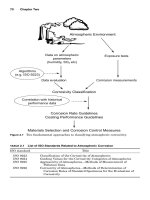
Corrosion Maintenance through Inspection and Monitoring 373
Operational Data
On-line
Off-line
Inspection
Engineering Reviews
Risk Based Assessments
Maintenance Management
Information for
Decision-Making
Data Base
Management System
Corrosion
Monitoring
Process
Parameters
Inhibitor and
Additive Dosing
Laboratory
Analysis
Reports, Notes
Trending
Correlations
Forecasting
Manual Data
Collection
Figure 6.1 Integration of corrosion inspection and monitoring programs for producing
management information.
0765162_Ch06_Roberge 9/1/99 5:01 Page 373
demonstrated repetitively that if an inspection department has control
over the condition of piping within a unit, the condition of the remain-
ing equipment will also be known with a relatively high degree of con-
fidence.
2
It is rare that corrosion or other forms of deterioration found
in major components of process equipment are not found in the inter-
connecting piping. The latter is generally more vulnerable to corrosion
and subject to initial failure because
■
The corrosion allowance on piping generally is only one-half that
provided for other pieces of refinery equipment.
■
Fluid velocities are often higher in piping, leading to accelerated cor-
rosion rates. (This is not always the case for certain localized corro-
sion processes.)
■
Piping design stresses normally are higher, and the piping system
may be subject to external loading, vibration, and thermal stresses
that are more severe than those encountered in other pieces of
equipment.
■
The larger number of inspection points in a piping system makes the
task of controlling and monitoring the system bigger.
Leaks in pressurized piping systems are extremely hazardous and
have led to several catastrophes. Components requiring close atten-
tion include
■
Lines operating at temperatures below the dew point
■
Lines operating in an industrial marine atmosphere
■
Points of entry and exit from a building, culvert, etc., where a break
in insulation could occur
■
Pipe support condition and fireproofing
376 Chapter Six
TABLE 6.1 Inspection Techniques Useful for the Detection of Underdeposit in
Boiler Systems
Inspection methods Application
On-line
Hydrogen analysis in saturated background General and steam localized corrosion
Tube temperature monitoring Deposit buildup
Chemistry (phosphate and pH) Buffering potential
Off-line
Visual examination (fiberscope, videoprobe) Steam blanketing
Gouging and tubercles
Tube sampling Deposit amount
Deposit constituents
0765162_Ch06_Roberge 9/1/99 5:01 Page 376
TABLE
6.2 Problems or Materials Damage Commonly Encountered in Piping Systems of Process Industries
Carbon steels At temperatures above 400 to 430°C, pearlite will convert to a spheroidal form of carbide and eventually,
under suitable conditions, to graphite. Spheroidization and graphitization lower the yield stress and ultimate
tensile strength, while increasing the ductility. The effect is significant in the heat-affected zone of a welded
joint, where graphite tends to form chains in a form known as “eyebrow” graphitization. This condition can
lead to severe embrittlement. Some weld failures caused by this type of deterioration have been reported in
the literature. In-place metallography and removal of samples can be used to check for this condition. C
steels operating above 430°C should be evaluated for possible graphitization after the first 30,000 h of
operation, and every 50,000 h thereafter.
Carbon-Mo steels Three types of damage to 0.5 Mo C steels are elevated-temperature hydrogen attack, graphitization, and
temper embrittlement. Where 0.5 Mo C steels are used in hydrogen service above the limits of the C-steel
line, pressure vessels (and heat exchangers) should be monitored using ultrasonic attenuation measurements
during unit downtime. Each plate in the vessel should be examined at each turnaround or at a maximum
interval of 2 years. The readings should be in the plate material immediately adjacent to a main seam weld,
which represents an area of maximum residual stress. In addition, any defects identified by other inspection
practices should be investigated by metallographic examination for hydrogen attack.
Low Cr-Mo steels While C steels tend to soften and become more ductile when exposed to temperatures around 400°C, low Cr-
Mo steels tend to undergo temper embrittlement. Embrittlement increases the strength of the material but
markedly decreases toughness by inhibiting plastic deformation. The 2.25 Cr 0.5 Mo steels are more
susceptible to temper embrittlement in the 370 to 480°C range. Not all the factors that affect temper
embrittlement in Cr-Mo steels are fully defined, but some estimate of fracture toughness after service can be
made from the chemical composition. The amount of shift in transition temperature for a 2.25 Cr-Mo
material is commonly expressed by the J factor: J factor ϭ (Si ϩ Mn) (P ϩ Sn) ϫ 10
4
. Steel containing 1.25 Cr
0.5 Mo may temper-embrittle at a temperature around 400°C if P ϩ Sn exceeds 0.03%. Steels containing 1.0
Cr 0.5 Mo do not undergo a serious loss of room-temperature ductility when used at this temperature.
378
0765162_Ch06_Roberge 9/1/99 5:01 Page 378