Handbook of Corrosion Engineering Episode 2 Part 9 ppt
Bạn đang xem bản rút gọn của tài liệu. Xem và tải ngay bản đầy đủ của tài liệu tại đây (525.91 KB, 40 trang )
Ideally an anode will corrode uniformly and approach its theoretical
efficiency. Passivation of an anode is obviously undesirable. Ease of
manufacturing in bulk quantities and adequate mechanical properties
are also important.
11.2.2 Anode materials and performance
characteristics
For land-based CP applications of structural steel, anodes based on zinc
or magnesium are the most important. Zinc anodes employed under-
ground are high-purity Zn alloys, as specified in ASTM B418-95a. Only
the Type II anodes in this standard are applicable to buried soil applica-
tions. The magnesium alloys are also high-purity grades and have the
advantage of a higher driving voltage. The low driving voltage of zinc
electrodes makes them unsuitable for highly resistive soil conditions.
The R892-91 guidelines of the Steel Tank Institute give the following dri-
ving voltages, assuming a structure potential of Ϫ850 mV versus CSE:
High potential magnesium. Ϫ0.95 V
High-purity zinc: Ϫ0.25 V
Magnesium anodes generally have a low efficiency at 50 percent or
even lower. The theoretical capacity is around 2200 Ah/kg. For zinc
anodes, the mass-based theoretical capacity is relatively low at 780
Ah/kg, but efficiencies are high at around 90 percent.
Anodes for industrial use are usually conveniently packaged in bags
prefilled with suitable backfill material. This material is important
because it is designed to maintain low resistivity (once wetted) and a
steady anode potential and also to minimize localized corrosion on the
anode.
The current output from an anode can be estimated from Dwight’s
equation (applicable to relatively long and widely spaced anodes) as
follows:
i ϭ
where i ϭ current output (A)
E ϭ driving voltage of the anode (V)
L ϭ anode length (cm)
ϭsoil resistivity (⍀иcm)
D ϭ anode diameter (cm)
The life expectancy of an anode is inversely proportional to the cur-
rent flowing and can be estimated with the following expression:
2EL
ᎏᎏ
ln (8L/D Ϫ 1)
Cathodic Protection 873
0765162_Ch11_Roberge 9/1/99 6:37 Page 873
Lifetime ϭ
where Lifetime ϭ anode life (years)
K ϭ anode consumption factor (0.093 for Zn, 0.253 for
Mg)
U ϭ utilization factor, a measure of the allowable anode
consumption before it is rendered ineffective (typi-
cally 0.85)
W ϭ mass of the anode (kg)
e ϭ efficiency of the anode (0.9 for Zn, 0.5 for Mg)
i ϭ current output (A)
11.2.3 System design and installation
The design of CP systems lies in the domain of experienced specialists.
Only the basic steps involved in designing a sacrificial anode system
are outlined. Prior to any detailed design work a number of funda-
mental factors such as the protection criteria, the type and integrity of
the coating system, the risk of stray current corrosion, and the pres-
ence of neighboring structures that could be affected by the CP system
have to be defined.
Buried structures in soils. For structures buried in soil, such as
pipelines, the first step in detailed design is usually to determine the
resistivity of the soil (or other electrolyte). This variable is essential for
determining the anodes’ current output and is also a general measure
of the environmental corrosiveness. The resistivity essentially repre-
sents the electrical resistance of a standardized cube of material.
Certain measurement devices thus rely on measuring the resistance of
a soil sample placed in a standard box or tube. A common way to make
in situ measurement is by the so-called Wenner four-pin method. In
this method, four equally spaced pins are driven into the ground along
a straight line. The resistivity is derived from an induced current
between the outer pin pair and the potential difference established
between the inner pair. An additional type of resistivity measurement
is based on electromagnetic inductive methods using a transmitter
and pickup coils.
The second design step addresses electrical continuity and the use of
insulating flanges. These parameters will essentially define the struc-
tural area of influence of the CP system. To ensure protection over dif-
ferent structural sections that are joined mechanically, electrical
bonding is required. In complex structures, insulated flanges can
restrict the spread of the CP influence.
KUeW
ᎏ
i
874 Chapter Eleven
0765162_Ch11_Roberge 9/1/99 6:37 Page 874
In the third step the total current requirements are estimated. For
existing systems, the current that has to be applied to achieve a cer-
tain potential distribution can be measured, but this is not possible
for new systems. For the latter case, current requirements have to be
determined based on experience, with two important variables stand-
ing out: First, the type of environment has to be considered for speci-
fying an adequate level of current density. For example, a soil
contaminated with active sulfate-reducing bacteria, leading to micro-
bial corrosion effects, typically requires a higher current density for
protection. The second important variable is the surface area that
requires protection. The total current requirements obviously
decrease with increasing quality of the surface coating. Field-coated
structures usually have higher current requirements compared with
factory-coated structures. The effective exposed area of coated struc-
tures used for design purposes should take coating deterioration with
time into account.
Following the above, a suitable anode material can be selected,
together with the number of anodes and anode size for a suitable out-
put and life combination. The anode spacing also has to be established
to obtain a suitable current distribution over the entire structure.
Provision also has to be made for test stations to facilitate basic per-
formance monitoring of the CP system. There are two basic types of
test station. In one type, a connection to the pipe by means of a shielded
lead wire is provided at the surface. Such a connection is useful for
monitoring the potential of the pipeline relative to a reference elec-
trode. The reference electrode may be a permanent installation. The
second type provides surface access to the anode-structure connection.
The current flowing from the anode to the structure can thereby be
conveniently monitored at the surface. More details may be found in
the publication of Peabody.
2
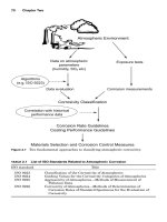
In urban centers test stations are usually recessed into the ground
with their covers flush with the pavement (Fig. 11.6). In outlying rural
areas test stations tend to be above ground in the form of test posts. It
is important to record the location of each test station. In urban areas
a locating system based on street names and position relative to lot
lines is commonly used. Locations relative to landmarks can be used
in rural situations. A more recent option is the Global Positioning
System (GPS) for finding test stations in the field. The relevant GPS
coordinates obviously have to be recorded initially, before GPS posi-
tioning units can be used for locating test stations. Affordable hand-
held GPS systems are now readily available for locating rural test
stations with reasonable accuracy.
Professional installation procedures are a key requirement for
ensuring adequate performance of sacrificial anode CP systems.
Cathodic Protection 875
0765162_Ch11_Roberge 9/1/99 6:37 Page 875
Following successful design and installation, the system is essentially
self-regulating. Although the operating principles are relatively sim-
ple, attention to detail is required, for example, in establishing wire
connections to the structure. The R892-91 guidelines of the Steel Tank
Institute highlight the importance of an installation information pack-
age that should be made available to the system installer. The follow-
ing are key information elements:
■
A site plan drawn to scale, identifying the size, quantity, and location
of anodes, location and types of test stations, layout of piping and
foundations
■
Detailed material specifications related to the anodes, test stations,
and coatings, including materials for coating application in the field
■
Site-specific installation instructions and/or manufacturer’s recom-
mended installation procedures
■
Inspection and quality control procedures for the installation phase
Submerged marine structures. Cathodic protection of submerged
marine structures such as steel jackets of offshore oil and gas plat-
forms and pipelines is widely provided by sacrificial anode systems. A
876 Chapter Eleven
Figure 11.6 Ground-level test station used in urban areas.
0765162_Ch11_Roberge 9/1/99 6:37 Page 876
commonly used protection criterion for such steel structures is Ϫ800
mV relative to a silver/silver chloride-reference electrode. In offshore
applications, impressed current systems are more vulnerable to
mechanical wear and tear of cabling and anodes. Compared to soils,
seawater has a low resistivity, and the low driving voltages of sacrifi-
cial anodes are thus of lower concern in the sea. The sacrificial anodes
in offshore applications are usually based on aluminum or zinc. The
chemical composition of an aluminum alloy specified for protecting an
offshore gas pipeline is presented in Table 11.3.
3
Close control over
impurity elements is crucial to ensure satisfactory electrochemical
behavior. Sydberger, Edwards, and Tiller
4
have presented an excellent
overview of designing sacrificial anode systems for submerged marine
structures, using a conservative approach. A brief summary of this
publication follows.
One of the main benefits of adequate design and a conservative
design approach is that future monitoring and maintenance require-
ments will be minimal. Correct design also ensures that the system will
essentially be self-regulating. The anodes will “automatically” provide
increased current output if the structure potential shifts to more posi-
tive values, thereby counteracting this potential drift. Furthermore, a
conservative design approach will avoid future costly retrofits. Offshore
in situ anode retrofitting tends to be extremely costly and will tend to
exceed the initial “savings.” Such a design approach has also proven
extremely valuable for requalification of pipelines, well beyond their
original design life. A conservative design approach is sensible when
considering that the cost of CP systems may only be of the order of 0.5
to 1% of the total fabrication and installation costs.
The two main steps involved in the design calculations are (1) cal-
culation of the average current demand and the total anode net mass
required to protect the structure over the design life and (2) the initial
and final current demands required to polarize the structure to the
required potential protection criterion. The first step is associated with
Cathodic Protection 877
TABLE 11.3 Chemical Composition of Anode
Material for an Offshore Pipeline
Element Maximum, wt. % Minimum, wt. %
Zinc 5.5 2.5
Indium 0.04 0.015
Iron 0.09 /
Silicon 0.10 /
Copper 0.005 /
Others, each 0.02 /
Aluminum Balance /
0765162_Ch11_Roberge 9/1/99 6:37 Page 877
the anticipated current density once steady-state conditions have been
reached. The second step is related to the number and size of individ-
ual anodes required under dynamic, unsteady conditions.
The cathodic current density is a complex function of various seawater
parameters, for which no “complete” model is available. For design pur-
poses, four climatic zones based on average water temperature and two
depth ranges have therefore been defined: tropical, subtropical, temper-
ate, and arctic. For example, in colder waters current densities tend to be
higher due to a lower degree of surface protection from calcareous layers.
One major design uncertainty is the quality (surface coverage) of the
coating. In subsea pipelines, the coating is regarded as the primary
corrosion protection measure, with CP merely as a back-up system.
For design purposes, not only do initial defects in the coating have to
be considered but also its degradation over time.
In general, because of design uncertainties and simplifications, a
conservative design approach is advisable. This policy is normally fol-
lowed through judicious selection of design parameters rather than
using an overall safety factor. Marginal designs will rarely result in
underprotection early in the structure’s life; rather the overall life of
the CP system will be compromised. Essentially, the anode consump-
tion rates will be excessive in underdesigned systems. Further details
may be found in design guides such as NACE RP0176-94 and Det
Norske Veritas (DNV) Practice RP B401.
11.3 Impressed Current Systems
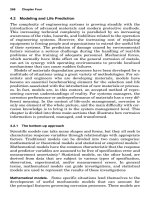
In impressed current systems cathodic protection is applied by means
of an external power current source (Fig. 11.7). In contrast to the sac-
rificial anode systems, the anode consumption rate is usually much
lower. Unless a consumable “scrap” anode is used, a negligible anode
consumption rate is actually a key requirement for long system life.
Impressed current systems typically are favored under high-current
requirements and/or high-resistance electrolytes. The following
advantages can be cited for impressed current systems:
■
High current and power output range
■
Ability to adjust (“tune”) the protection levels
■
Large areas of protection
■
Low number of anodes, even in high-resistivity environments
■
May even protect poorly coated structures
The limitations that have been identified for impressed current CP
systems are
878 Chapter Eleven
0765162_Ch11_Roberge 9/1/99 6:37 Page 878
■
Relatively high risk of causing interference effects.
■
Lower reliability and higher maintenance requirements.
■
External power has to be supplied.
■
Higher risk of overprotection damage.
■
Risk of incorrect polarity connections (this has happened on occasion
with much embarrassment to the parties concerned).
■
Running cost of external power consumption.
■
More complex and less robust than sacrificial anode systems in cer-
tain applications.
The external current supply is usually derived from a transformer-
rectifier (TR), in which the ac power supply is transformed (down) and
rectified to give a dc output. Typically, the output current from such
Cathodic Protection 879
Ground
Level
Inert or
Consumable
Anode
Backfill in
Groundbed
Ionic Current in Soil
Coated
Copper Cable
Steel Pipe (Cathode)
+
-
Current due to Electron
Flow in Cable
DC Current Supply
(Transformer-Rectifier)
Figure 11.7 Principle of cathodic protection with impressed current (schematic).
0765162_Ch11_Roberge 9/1/99 6:37 Page 879
units does not have pure dc characteristics; rather considerable “rip-
ple” is inevitable with only half-wave rectification at the extreme end
of the spectrum. Other power sources include fuel- or gas-driven gen-
erators, thermoelectric generators, and solar and wind generators.
Important application areas of impressed current systems include
pipelines and other buried structures, marine structures, and rein-
forcing steel embedded in concrete.
11.3.1 Impressed current anodes
Impressed current anodes do not have to be less noble than the struc-
ture that they are protecting. Although scrap steel is occasionally used
as anode material, these anodes are typically made from highly corro-
sion-resistant material to limit their consumption rate. After all,
under conditions of anodic polarization, very high dissolution rates can
potentially be encountered. Anode consumption rates depend on the
level of the applied current density and also on the operating environ-
ment (electrolyte). For example, the dissolution rate of platinized tita-
nium anodes is significantly higher when buried in soil compared with
their use in seawater. Certain contaminants in seawater may increase
the consumption rate of platinized anodes. The relationship between
discharge current and anode consumption rate is not of the simple lin-
ear variety; the consumption rate can increase by a higher percentage
for a certain percentage increase in current.
Under these complex relationships, experience is crucial for select-
ing suitable materials. For actively corroding (consumable) materials
approximate consumption rates are of the order of grams per ampere-
hour (Ah), whereas for fully passive (nonconsumable) materials the
corresponding consumption is on the scale of micrograms. The con-
sumption rates for partly passive (semiconsumable) anode materials
lie somewhere in between these extremes.
The type of anode material has an important effect on the reactions
encountered on the anode surface. For consumable metals and alloys such
as scrap steel or cast iron, the primary anodic reaction is the anodic
metal dissolution reaction. On completely passive anode surfaces, metal
dissolution is negligible, and the main reactions are the evolution of
gases. Oxygen can be evolved in the presence of water, whereas chlorine
gas can be formed if chloride ions are dissolved in the electrolyte. The
reactions have already been listed in the theory section of this chapter.
The above gas evolution reactions also apply to nonmetallic conducting
anodes such as carbon. Carbon dioxide evolution is a further possibility
for this material. On partially passive surfaces, both the metal dissolution
and gas evolution reactions are important. Corrosion product buildup is
obviously associated with the former reaction.
880 Chapter Eleven
0765162_Ch11_Roberge 9/1/99 6:37 Page 880
It is apparent that a wide range of materials can be considered for
impressed current anodes, ranging from inexpensive scrap steel to
high-cost platinum. Shreir and Hayfield
5
identified the following desir-
able properties of an “ideal” impressed current anode material:
■
Low consumption rate, irrespective of environment and reaction
products
■
Low polarization levels, irrespective of the different anode reactions
■
High electrical conductivity and low resistance at the anode-electrolyte
interface
■
High reliability
■
High mechanical integrity to minimize mechanical damage during
installation, maintenance, and service use
■
High resistance to abrasion and erosion
■
Ease of fabrication into different forms
■
Low cost, relative to the overall corrosion protection scheme
In practice, important trade-offs between performance properties
and material cost obviously have to be made. Table 11.4 shows selected
anode materials in general use under different environmental condi-
tions. The materials used for impressed anodes in buried applications
are described in more detail below.
11.3.2 Impressed current anodes for buried
applications
The NACE International Publication 10A196 represents an excel-
lent detailed description of impressed anode materials for buried
Cathodic Protection 881
TABLE 11.4 Examples of Impressed Current Anodes Used in Different
Environments
Marine High-purity
environments Concrete Potable water Buried in soil liquids
Platinized surfaces Platinized High-Si iron Graphite Platinized
Iron, and steel surfaces Iron and steel High-Si Cr surfaces
Mixed-metal oxides Mixed-metal Graphite cast iron
graphite oxides Aluminum High-Si iron
Zinc Polymeric Mixed-metal
High-Si Cr cast iron oxides
Platinized
surfaces
Polymeric, iron
and steel
0765162_Ch11_Roberge 9/1/99 6:37 Page 881
applications. Further detailed accounts are also given by Shreir and
Hayfield
5
and Shreir, Jarman, and Burstein;
6
only a brief summary
is provided here.
Graphite anodes have largely replaced the previously employed car-
bon variety, with the crystalline graphite structure obtained by high-
temperature exposure as part of the manufacturing process that
includes extrusion into the desired shape. These anodes are highly
porous, and it is generally desirable to restrict the anode reactions to
the outer surface to limit degradation processes. Impregnation of the
graphite with wax, oil, or resins seals the porous structure as far as
possible, thereby reducing consumption rates by up to 50 percent.
Graphite is extremely chemically stable under conditions of chloride
evolution. Oxygen evolution and the concomitant formation of carbon
dioxide gas accelerate the consumption of these anodes. Consumption
rates in practice have been reported as typically between 0.1 to 1 kg
A
–1
y
–1
and operating currents in the 2.7 to 32.4 A/m
2
range. Buried
graphite anodes are used in different orientations in anode beds that
contain carbonaceous backfill.
The following limitations apply to graphite anodes: Operating current
densities are restricted to relatively low levels. The material is inher-
ently brittle, with a relatively high risk of fracture during installation
and operational shock loading. In nonburied applications, the settling
out of disbonded anode material can lead to severe galvanic attack of
metallic substrates (most relevant to closed-loop systems) and, being
soft material, these anodes can be subject to erosion damage.
Platinized anodes are designed to remain completely passive and
utilize a surface coating of platinum (a few micrometers thick) on tita-
nium, niobium, and tantalum substrates for these purposes.
Restricting the use of platinum to a thin surface film has important
cost advantages. For extended life, the thickness of the platinum sur-
face layer has to be increased. The inherent corrosion resistance of the
substrate materials, through the formation of protective passive
films, is important in the presence of discontinuities in the platinum
surface coating, which invariably arise in practice. The passive films
tend to break down at a certain anodic potential, which is dependent
on the corrosiveness of the operating environment. It is important
that the potential of unplatinized areas on these anodes does not
exceed the critical depassivation value for a given substrate material.
In chloride environments, tantalum and niobium tend to have higher
breakdown potentials than titanium, and the former materials are
thus preferred at high system voltages.
These anodes are fabricated in the form of wire, mesh, rods, tubes,
and strips. They are usually embedded in a ground bed of carbona-
ceous material. The carbonaceous backfill provides a high surface area
882 Chapter Eleven
0765162_Ch11_Roberge 9/1/99 6:37 Page 882
(fine particles are used) and lowers the anode/earth resistance; effec-
tive transfer of current between the platinized surfaces and the back-
fill are therefore important. Reported consumption rates are less than
10 mg A
–1
y
–1
under anodic chloride evolution and current densities up
to 5400 A/m
2
. In oxygen evolution environments reported consumption
rates are of the order of 16 mg/A-y at current densities below 110 A/m
2
.
In the presence of current ripple effects, platinum consumption rates
are increased, particularly at relatively low frequencies.
Limitations include current attenuation in long sections of wire.
Uneven current distribution results in premature localized anode
degradation, especially near the connection to a single current feed
point. Multiple feed points improve the current distribution and pro-
vide system redundancy in the event of excess local anode dissolution.
Current ripple effects, especially at low frequencies, should be avoided.
The substrate materials are at risk to hydrogen damage if these
anodes assume a cathodic character outside of their normal opera-
tional function (for example, if the system is de-energized).
Mixed-metal anodes also utilize titanium, niobium, and tantalum as
substrate materials. A film of oxides is formed on these substrates,
with protective properties similar to the passive film forming on the
substrate materials. The important difference is that whereas the
“natural” passive film is an effective electrical insulator, the mixed
metal oxide surface film passes anodic current. The product forms are
similar to those of the platinized anodes. These anodes are typically
used with carbonaceous backfill. Electrode consumption is usually not
the critical factor in determining anode life; rather the formation of
nonconductive oxides between the substrate and the conductive sur-
face film limits effective functioning. Excessive current densities accel-
erate the buildup of these insulating oxides to unacceptable levels.
Scrap steel and iron represent consumable anode material and have
been used in the form of abandoned pipes, railroad or well casings, as
well as any other scrap steel beams or tubes. These anodes found
application particularly in the early years of impressed current CP
installations. Because the dominant anode reaction is iron dissolution,
gas production is restricted at the anode. The use of carbonaceous
backfill assists in reducing the electrical resistance to ground associ-
ated with the buildup of corrosion products. Periodic flooding with
water can also alleviate resistance problems in dry soils.
Theoretical anode consumption rates are at 9 kg A
–1
y
–1
. For cast
iron (containing graphite) consumption rates may be lower than theo-
retical due to the formation of carbon-rich surface films. Full utiliza-
tion of the anode is rarely achieved in practice due to preferential
dissolution in certain areas. Fundamentally, these anodes are not
prone to failure at a particular level of current density. For long anode
Cathodic Protection 883
0765162_Ch11_Roberge 9/1/99 6:37 Page 883
lengths, multiple current feed points are recommended to ensure a
reasonably even current distribution over the surface and prevent pre-
mature failure near the feed point(s).
Limitations include the buildup of corrosion products that will
gradually lower the current output. Furthermore, in high-density
urban areas, the use of abandoned structures as anodes can have
serious consequences if these are shorted to foreign services. An aban-
doned gas main could, for example, appear to be a suitable anode for
a new gas pipeline. However, if water mains are short circuited to the
abandoned gas main in certain places, leaking water pipes will be
encountered shortly afterward due to excessive anodic dissolution.
High-silicon chromium cast iron anodes rely on the formation of
a protective oxide film (mainly hydrated SiO
2
) for corrosion resistance.
The chromium alloying additions are made for use in chloride-
containing environments to reduce the risk of pitting damage. These
anodes can be used with or without carbonaceous backfill; in the lat-
ter case the resistance to ground is increased (particularly under dry
conditions) as are the consumption rates. Consumption rates have
been reported to typically range between 0.1 to 1 kg A
–1
y
–1
. The cast-
ings are relatively brittle and thus susceptible to fracture under shock
loading.
Polymeric anodes are flexible wire anodes with a copper core sur-
rounded by a polymeric material that is impregnated with carbon. The
impregnated carbon is gradually consumed in the conversion to carbon
dioxide, with ultimate subsequent failure by perforation of the copper
strand. The anodes are typically used in combination with carbona-
ceous backfill, which reportedly increases their lifetime substantially.
Because these anodes are typically installed over long lengths, prema-
ture failures are possible when soil resistivity varies widely.
11.3.3 Ground beds for buried structures
From the above description, the important role played by the ground
beds in which the impressed current anodes are located should already
be apparent. Carbonaceous material (such as coke breeze and graphite)
used as backfill increases the effective anode size and lowers the resis-
tance to soil. It is important to realize that, with such backfill, the
anodic reaction is mainly transferred to the backfill. The consumption
of the actual anode material is thereby reduced. To ensure low resistiv-
ity of the backfill material, its composition, particle size distribution,
and degree of compaction (tamping) need to be controlled. The latter
two variables also affect the degree to which gases generated at the
anode installation can escape. If it is difficult to establish desirable
backfill properties consistently in the ground, prepackaged anodes and
884 Chapter Eleven
0765162_Ch11_Roberge 9/1/99 6:37 Page 884
backfill inside metal canisters can be considered. Obviously these can-
isters will be consumed under operational conditions.
The anodes may be arranged horizontally or vertically in the ground
bed. The commonly used cylindrical anode rods may be the long con-
tinuous variety or a set of parallel rods. Some advantageous features
of vertical deep anode beds include lower anode bed resistance, lower
risk of induced stray currents, lower right-of-way surface area
required, and improved current distribution in certain geometries.
Limitations that need to be traded off include higher initial cost per
unit of current output, repair difficulties, and increased risk of gas
blockage.
At very high soil resistivities, a ground bed design with a continu-
ous anode running parallel to a pipeline may be required. In such
environments discrete anodes will result in a poor current distribu-
tion, and the potential profile of the pipeline will be unsatisfactory.
The pipe-to-soil potential may only reach satisfactory levels in close
proximity to the anodes if discontinuous anodes are employed in high-
resistivity soil.
11.3.4 System design
Just as for sacrificial anode systems, design of impressed current CP
systems is a matter for experienced specialists. The first three basic
steps are similar to sacrificial anode designs, namely, evaluation of
environmental corrosivity (soil resistivity is usually the main factor
considered), determining the extent of electrical continuity in the sys-
tem, and subsequently estimating the total current requirements.
One extremely useful concept to determine current requirements in
existing systems is current drain testing. In these tests, a CP current
is injected into the structure with a temporary dc power source. Small
commercial units supplying up to 10 A of current are available for
these purposes. A temporary anode ground bed is also required;
grounded fixtures such as fences, fire hydrants, or street lights have
been used. Potential loggers have to be installed at selected test sta-
tions to monitor the potential response to the injected current. The
recorded relationship between potential and current is used to define
what current level will be required to reach a certain protection crite-
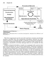
rion. An example of results from a current drain test performed on a
buried, coated steel pipeline is presented in Fig. 11.8. Once the data
loggers and current-supply hardware have been installed, these tests
usually only require a few minutes of time.
Following the completion of the above three steps, the anode geom-
etry and material have to be specified, together with a ground bed
design. The designer needs to consider factors such as uniformity of
Cathodic Protection 885
0765162_Ch11_Roberge 9/1/99 6:37 Page 885
current distribution (see separate section below), possible interference
effects (see Sec. 11.4.3), the availability of electrical power, and local
bylaws and policies with respect to rectifier locations. Once the circuit
layout and cabling are defined, the circuit resistance can be calculated
and the rectifier can subsequently be sized in terms of current and
potential output. Lastly, consideration must be given to the design of
ancillary equipment for control purposes and test stations for moni-
toring purposes. Modern designs include provisions for remote rectifier
performance monitoring and remote rectifier output adjustments.
11.4 Current Distribution and Interference
Issues
11.4.1 Corrosion damage under disbonded
coatings
It has already been stated that in buried cathodically protected struc-
tures, a surface coating is in fact the primary form of corrosion protec-
tion, with CP as a secondary measure. Users of this double protection
methodology are sometimes surprised to find that severe localized cor-
rosion damage has occurred under a coating, despite the two-fold pre-
886 Chapter Eleven
-1.3
1 501 1001 1501 2001 2501 3001 3501 4001 4501 5001 5501
-1.2
-1.1
-1
-0.9
-0.8
-0.7
-0.6
-0.5
-0.4
Time (half second intervals)
Potential (Volts vs CSE)
10 A test current
8.5 A test current
4 A test current
Figure 11.8 Current drain test results for a buried steel pipeline.
0765162_Ch11_Roberge 9/1/99 6:37 Page 886
ventive measures. Such localized corrosion damage has been observed
in both sacrificial anode and impressed current CP systems.
Importantly, it may not be possible to detect such problems in struc-
ture-to-soil potential surveys.
The phenomenon of coating disbondment plays a major role in this
type of problem. The protective properties of a coating are greatly
dependent on its ability to resist disbondment around defects.
7
The pro-
tective properties of the coating are compromised when water enters the
gap between the (disbonded) coating and the metallic surface. A corro-
sive microenvironment will tend to develop in such a situation.
Depending on the nature of this microenvironment, the CP system may
not be able to protect the surface under the disbondment. Only when the
trapped water has a high conductivity (e.g., saline conditions) will a pro-
tective potential be projected under the disbondment.
8
In the absence of
protective CP effects, the surface will corrode under the free corrosion
potential of the particular microenvironment that is established.
Jack, Wilmott, and Sutherby
8
identified three primary corrosion sce-
narios that could be manifested under shielded disbonded coatings on
buried steel pipelines, together with secondary transformations of the
primary sites (Table 11.5). A brief description follows.
Aerobic sites. Under aerobic conditions, oxygen reduction is the
dominant cathodic reaction. Corrosion rates thus depend on the
mass transport of oxygen to the steel surface. Under stagnant con-
ditions, oxygen diffusion into the solution under the shielded dis-
bondment is the rate-limiting step. The formation of surface oxides
is also important for corrosion kinetics. The main corrosion products
expected under aerobic conditions are iron (III) oxides/hydroxides.
Anaerobic sites. Hydrogen evolution is a prime candidate for the
cathodic half-cell reaction under anaerobic conditions. Corrosion
rates therefore tend to increase with decreasing pH (increasing acid-
ity levels). In the case of ground water saturated with calcium and
carbonate, the corrosion product is mainly iron (II) carbonate, a
milky white precipitate. On exposure to air this white product will
revert rapidly to reddish iron (III) oxides.
Cathodic Protection 887
TABLE 11.5 Primary Corrosion Scenarios and Transformations at
Disbonded Coating Sites for Steel Pipelines Buried in Alberta Soil
Primary corrosion scenario Secondary transformation
Aerobic Anaerobic ϩ sulfate reducing bacteria (SRB)
Anaerobic Aerobic
Anaerobic ϩ SRB Aerobic
0765162_Ch11_Roberge 9/1/99 6:37 Page 887
Anaerobic sites with sulfate reducing bacteria (SRB). Highly corro-
sive microenvironments tend to be created under the influence of
SRB; they convert sulfate to sulfide in their metabolism. Likely cor-
rosion products are black iron (II) sulfide (in various mineral forms)
and iron (II) carbonate. SRB tend to thrive under anaerobic condi-
tions. These chemical species will again tend to change if the corro-
sion cell is disturbed and aerated.
Secondary transformations. Changing soil conditions can lead to
transformations in the primary corrosion sites. After all, soil condi-
tions are dynamic with variations in humidity, temperature, water
table levels, and so forth. For example, mixtures of iron (II) carbonate
and iron (III) oxides and the relative position of these species have
indicated dominant transformations from anaerobic to aerobic condi-
tions, with the reddish products encapsulating the white species.
The transformation from anaerobic sites to aerobic sites is a drastic
one, with high CP current demand and extremely high corrosion rates.
Iron (II) sulfides are oxidized to iron (III) oxides and sulfur species. In
turn, sulfur is ultimately oxidized to sulfate.
The change of aerobic sites to anaerobic sites with SRB leads to
reduction of Fe (III) oxides to iron sulfide species. The conversion
kinetics are pH dependent. Increasingly corrosive conditions should be
anticipated with the formation of sulfide species.
11.4.2 General current distribution and
attenuation
In practice, the current distribution in CP systems tends to be far
removed from idealized uniform current profiles. It is the nature of
electron current flow in structures and the nature of ionic current flow
in the electrolyte between the anode and the structure that influence
the overall current distribution. A number of important factors affect
the current distribution, as outlined below.
One underlying factor is the anode-to-cathode separation distance.
In general, too close a separation distance results in a poor distribu-
tion, as depicted in Fig. 11.9. A trade-off that must be made, when
increasing this distance, is the increased resistance to current flow. At
excessive distances, the overall protection levels of a structure may be
compromised for a given level of power supply. Additional anodes can
be used to achieve a more homogeneous ionic current flow, where an
optimum anode-to-cathode separation distance cannot be achieved.
Resistivity variations in the electrolyte between the anode and cath-
ode also have a strong influence on the current distribution. Areas of
low resistivity will “attract” a higher current density, with current
flowing preferentially along the path of least resistance. An example of
888 Chapter Eleven
0765162_Ch11_Roberge 9/1/99 6:37 Page 888
such an unfavorable situation is illustrated in Fig. 11.10. Similar prob-
lems may be encountered in deeply buried structures, when different
geological formations and moisture contents are encountered with
increasing depth from the surface. An indication of resistivity varia-
tions across different media is given in Table 11.6.
Another important factor for coated structures is the presence of
defects in the protective coating. Not only does the size of a defect
affect the current but also the position of the defect relative to the
anode. Current tends to be concentrated locally at defects. A funda-
mental source of nonuniformly distributed CP current over structures
results from an effect known as attenuation. In long structures such as
pipelines the electrical resistance of the structure itself becomes sig-
nificant. The resistance of the structure causes the current to decrease
nonlinearly as a function of distance from a drain point. A drain point
refers to the point on the structure where its electrical connection to
the anode is made. This characteristic decrease in current (and also in
potential), shown in Fig. 11.11, occurs even under the following ideal-
ized conditions:
■
The anodes are sufficiently far removed from the structure.
■
The electrolyte resistivity is completely uniform between the
anode(s) and the structure.
Cathodic Protection 889
Overprotection
Underprotection
Overprotection
Anode
Anode
Structure
Current supply to this side of structure is also limited
if anodes are too close to structure
Current distribution is
improved by moving
anode back
Current distribution is
improved by moving
anode back
Concentration of current at
path of lowest resistance
Figure 11.9 Nonuniform distribution of protective current resulting from anode posi-
tioning too close to the corroding structure (schematic).
0765162_Ch11_Roberge 9/1/99 6:37 Page 889
■
The coating has a high and uniform ohmic resistance.
■
A linear relationship exists between the potential of the structure
and the current.
Under these idealized conditions the following attenuation equa-
tions apply
E
x
ϭ E
0
exp (Ϫ␣x)
I
x
ϭ I
0
exp (Ϫ␣x)
where E
0
and I
0
are the potential and current at the drainage point,
and x is the distance from the drainage point.
The attenuation coefficient ␣ is defined as
890 Chapter Eleven
Anode
Pipeline
High current flow
Low current flow
Highly negative potential Less negative potential
DC
Power
Supply
Sandy Soil
(high resistivity)
Swamp
(low resistivity)
Figure 11.10 Nonuniform current distribution over a pipeline resulting from differences
in the electrolyte (soil) resistivity (schematic). The main current flow will be along the
path of least resistance.
TABLE 11.6 Resistivities of Different
Electrolytes
Soil type Typical resistivity, ⍀иcm
Clay (salt water) Ͻ 1000
Clay (fresh water) Ͻ 2000
Marsh 1000–3000
Humus 1000–4000
Loam 3000–10,000
Sand Ͼ 10,000
Limestone Ͼ 20,000
Gravel Ͼ 40,000
0765162_Ch11_Roberge 9/1/99 6:37 Page 890
␣ϭ
where R
S
is the ohmic resistance of the structure per unit length and
R
K
is given by
R
K
ϭ
͙
R
ෆ
S
ෆ
R
ෆ
L
ෆ
where R
L
is known as the leakage resistance and refers to the total
resistance of the structure-electrolyte interface, including the ohmic
resistance of any applied surface coating(s).
R
S
ᎏ
R
K
Cathodic Protection 891
Potential
Current
Distance from drain point
Distance from drain point
0
0
Current decreases with
distance away from
the drain point
Potential values become less
negative with distance
away from the drain point
Figure 11.11 Potential and current attenuation as a function of distance from the drain
point, due to increasing electrical resistance of the pipeline itself (schematic).
0765162_Ch11_Roberge 9/1/99 6:37 Page 891
To minimize attenuation, the term ␣ should be as small as possible.
This implies that for a given material a high R
K
value is desirable.
Because the ohmic resistance of the structure R
S
is fixed for a given
material, the leakage resistance R
L
needs to be considered. The higher
the integrity of the coating, the higher R
L
will be. The buildup of cal-
careous deposits on exposed areas of cathodically protected structures
will also tend to increase R
L
. The formation of such deposits is there-
fore desirable for attenuation considerations. For achieving a relative-
ly uniform current distribution in CP systems, the following factors
are thus generally regarded as desirable:
■
Relatively high electrolyte resistance
■
Uniform electrolyte resistance
■
Low resistivity of the structure
■
High quality of coating (high resistance)
■
Relatively high anode to cathode separation distance
■
Sufficiently large power supply in the CP system
11.4.3 Stray currents
Stray currents are currents flowing in the electrolyte from external
sources, not directly associated with the cathodic protection system.
Any metallic structure, for example, a pipeline, buried in soil repre-
sents a low-resistance current path and is therefore fundamentally
vulnerable to the effects of stray currents. Stray current tends to enter
a buried structure in a certain location and leave it in another. It is
where the current leaves the structure that severe corrosion can be
expected. Corrosion damage induced by stray current effects has also
been referred to as electrolysis or interference. For the study and
understanding of stray current effects it is important to bear in mind
that current flow in a system will not only be restricted to the lowest-
resistance path but will be distributed between paths of varying resis-
tance, as predicted by elementary circuit theory. Naturally, the current
levels will tend to be highest in the paths of least resistance.
There are a number of sources of undesirable stray currents, includ-
ing foreign cathodic protection installations; dc transit systems such
as electrified railways, subway systems, and streetcars; welding oper-
ations; and electrical power transmission systems. Stray currents can
be classified into three categories
1. Direct currents
2. Alternating currents
3. Telluric currents
892 Chapter Eleven
0765162_Ch11_Roberge 9/1/99 6:37 Page 892
Direct stray current corrosion. Typically, direct stray currents come
from cathodic protection systems, transit systems, and dc high-voltage
transmission lines. A distinction can be made between anodic interfer-
ence, cathodic interference, and combined interference.
Anodic interference is found in relatively close proximity to a buried
anode, under the influence of potential gradients surrounding the
anode. As shown in Fig. 11.12, a pipeline will pick up current close to
the anode. This current will be discharged at a distance farther away
from the anode. In the current pickup region, the potential of the
pipeline subject to the stray current will shift in the negative direction;
in essence it receives a boost of cathodic protection current locally. This
local current boost will not necessarily be beneficial, because a state of
overprotection could be created. Furthermore, the excess of alkaline
species generated can be harmful to aluminum and lead alloys.
Conversely, in areas where the stray current is discharged, its poten-
tial will rise to more positive values. It is in the areas of current dis-
charge that anodic dissolution is the most severe.
Cathodic interference is produced in relatively close proximity to a
polarized cathode. As shown in Fig. 11.13, current will flow away from
the structure in the region in close proximity to the cathode. The
potential will shift in the positive direction where current leaves this
structure, and this area represents the highest corrosion damage risk.
Current will flow onto the structure over a larger area, at further dis-
tances from the cathode, again with possible damaging overprotection
effects.
An example of combined anodic and cathodic interference is pre-
sented in Fig. 11.14. In this case current pickup occurs close to an
Cathodic Protection 893
Protected structure
Pipeline subject to interference
Anode
Current discharge
leading to less
negative potentials
Current discharge
leading to less
negative potentials
Current pickup leading to
more negative potentials
Figure 11.12 Anodic interference example (schematic).
0765162_Ch11_Roberge 9/1/99 6:37 Page 893
anode, and current discharge occurs close to a cathodically polarized
structure. The degree of damage of the combined stray current effects
is greater than in the case of anodic or cathodic interference acting
alone. The effects are most pronounced if the current pickup and dis-
charge areas are in close proximity. Correspondingly, the damage in
both the current pickup (overprotection effects) and discharge regions
(corrosion) will be greater.
Alternating current. There is an increasing trend for pipelines and
overhead powerlines to use the same right-of-way. Alternating stray
current effects arise from the proximity of buried structures to high-
voltage overhead power transmission lines. There are two dominant
mechanisms by which these stray currents can be produced in
buried pipelines: electromagnetic induction and transmission line
faults.
894 Chapter Eleven
Protected structure
Pipeline subject to interference
Anode
Current discharge leading
to less negative potentials
Current pickup leading to
more negative potentials
Figure 11.13 Cathodic interference example (schematic).
0765162_Ch11_Roberge 9/1/99 6:37 Page 894
In the electromagnetic coupling mechanism, a voltage is induced in
a buried structure under the influence of the alternating electromag-
netic field surrounding the overhead transmission line. This effect is
similar to the coupling in a transformer, with the overhead transmis-
sion line acting as the primary transformer coil and the buried struc-
ture acting as the secondary coil. The magnitude of the induced
voltage depends on factors such as the separation distance from the
powerline, the relative position of the structure to the powerlines, the
proximity to other buried structures, and the coating quality. Such
induced voltages can be hazardous to anyone who comes in contact
with the pipeline or its accessories.
9
The second mechanism is one of resistive coupling, whereby ac cur-
rents are directly transmitted to earth during transmission line faults.
Causes of such faults include grounding of an overhead conductor,
lightning strikes, and major load imbalances in the conductors.
Usually such faults are of very short duration, but due to the high cur-
rents involved, substantial physical damage to coated structures is
possible. Ancillary equipment such as motorized valves, sensors, and
Cathodic Protection 895
Protected structure
Pipeline subject to interference
Anode
Current discharge leading
to less negative potentials
Current pickup leading to
more negative potentials
Figure 11.14 Combined anodic and cathodic interference example (schematic).
0765162_Ch11_Roberge 9/1/99 6:37 Page 895
cathodic protection stations could also be damaged. These faults rep-
resent a major threat to human and animal life, even if no contact is
made with the pipeline. The example listed in Table 11.7
10
for a
pipeline provides an indication of the relative magnitude of these two
mechanisms. Further details, including safety issues, may be found in
the publication of Kirkpatrick.
9
Telluric effects. These stray currents are induced by transient geomag-
netic activity. The potential and current distribution of buried struc-
tures can be influenced by such disturbances in the earth’s magnetic
field. Such effects, often assumed to be of greatest significance in closer
proximity to the poles, have been observed to be most intense during
periods of intensified sun spot activity. In general, harmful influences
on structures are of limited duration and do not remain highly localized
to specific current pickup and discharge areas. Major corrosion prob-
lems as a direct result of telluric effects are therefore relatively rare.
Geomagnetic activity for different locations is recorded and reported
by organizations such as the Geological Survey of Canada. Activity is
classified into quiet, unsettled, and active conditions. Furthermore,
charts forecasting magnetic activity are available, similar to short-
and long-term weather forecasts. Such forecast data has proven useful
to avoid measurements of pipeline “baseline” corrosion parameters
during sporadic periods of high geomagnetic transients.
Controlling stray current corrosion. In implementing countermeasures
against stray current effects, the nature of the stray currents has to be
considered. For mitigating dc interference, the following fundamental
steps can be taken:
■
Removal of the stray current source or reduction in its output current
■
Use of electrical bonding
896 Chapter Eleven
TABLE 11.7 Example of Fault Effect Calculation
Route length 4.1 km
Overhead supply system voltage 66 kV
Supply system fault current Three-phase 6350 A
Single-phase to earth 1600 A
Fault current duration Three phase: 0.68 s
Single-phase to earth: 0.12 s
Fault trip operation Single trip
Maximum induced voltage on pipe under
normal current load Ϫ2.5 V
Maximum induced voltage on pipe under
fault current Ϫ1050 V
0765162_Ch11_Roberge 9/1/99 6:37 Page 896
■
Cathodic shielding
■
Use of sacrificial anodes
■
Application of coatings to current pickup areas
To implement the first obvious option in the above listing, coopera-
tion from the owners of the source is a prerequisite. In several cases,
so-called electrolysis committees have been formed to serve as forums
for cooperation between different organizations.
The establishment of an electrical connection between the interfer-
ing and interfered-with structure is a common remedial measure.
Figure 11.15 shows how the interference problem presented in Fig.
11.12 is mitigated by an electrical bond created between the two struc-
tures. A variable resistance may be used in the bonded connection. A
so-called forced drainage bond imposes an additional external poten-
tial on the bond to “assist” stray current drainage through the bond. In
practice, for complex systems, the design of bonds is not a simple mat-
ter. Furthermore, stray currents tend to be dynamic in nature, with
the direction of current reversing from time to time. In such cases,
simple bonding is insufficient, and additional installation of diodes
will be required to protect a critical structure at all times.
In cathodic shielding the aim is to minimize the amount of stray
current reaching the structure at risk. A metallic barrier (or
“shield”) that is polarized cathodically is positioned in the path of
the stray current, as shown in Fig. 11.16. The shield represents a
low-resistance preferred path for the stray current, thereby mini-
mizing the flow of stray current onto the interfered-with structure.
Cathodic Protection 897
Protected structure
Protected structure
Anode
Figure 11.15 Use of a drainage bond to mitigate stray current discharge from the
pipeline (schematic).
0765162_Ch11_Roberge 9/1/99 6:37 Page 897