Handbook of Lubrication Episode 1 Part 6 docx
Bạn đang xem bản rút gọn của tài liệu. Xem và tải ngay bản đầy đủ của tài liệu tại đây (697.15 KB, 18 trang )
FIGURE 12.Two elliptical oil lift pockets located at quarter points along a journal bearing
axis. Removing the plug allows the supply passages to be flushed.
with size. A
L
, the area of a single bearing pocket, is usually made about 1.5% of Ain a
bearing of this type.
Once the load is lifted, the pocket pressure falls because pressurized oil is distributed
over the whole bearing area. The flow, oil film thickness, and other quantities can be
calculated for this condition as a pure hydrostatic bearing (before rotation starts). The lift
is the following function of the purnp flow:
(14)
This is the corrected form of Equation (12–19) in Reference 12.
Anumerical example will illustrate the use of the above equations, where Q = 0.07 ᐉ/
sec (1.1 gpm), D = 533.4 mm (21 in.), L = 304.8 mm (12 in.), C
D
= 0.711 mm (0.028
in.), W = 382,500 N (86,000 lb), n = 2 pockets, A
L
= 2580 mm
2
(4 in.
2
), and μ =
0.058 Pa·sec (8.4 µreyn).
Solving Equation 13, assuming K
BA
= 3, gives a breakaway pressure of 21.1 MPa (3072
psi). The oil pump should be sized to give at least this much pressure with some margin
(say, 50 to 100%) to allow for performance deterioration over a period of time. Employing
appropriate units, Equation 14 gives an eccentricity ratio of 0.63. Assuming that the shaft
moves straight up, the lift equals the minimum film thickness, (1 – ⑀)(C
D
/2), or 0.132 mm
(0.005 in.). This is a realistic value which will allow for some misalignment or shaft
deflection.
In thrust bearings somewhat more pocket area has historically been used than in journal
bearings, about 5%of the bearing area. The pad in Figure 13 is from a bearing with an
outside diameter of 2286 mm (90 in.) with a design load of 4.1 MPa (600 psi). At breakaway
the pocket pressure rises to 12.4 MPa (1800 psi). It then falls back to a steady-state value
of 4.8 MPa (700 psi).
‘The lift (h) may be estimated by assuming a circular pressure distribution similar to the
bearing in Figure 3. For the bearing pad in Figure 13 the following values may be assigned
to the variables: Q = 0.025 ᐉ/sec (0.4 gpm), P
p
= 4.8 MPa (700 psi), μ = 0.056 Pa·sec
(56 cP), (ISO VG 68 oil at 38°C), R = 286 mm (11.3 in.), and R
o
= 51 mm (2.0 in.).
Solving Equation 9 for h, using consistent units, gives a lift of 0.099 mm (0.004 in.),
118 CRC Handbook of Lubrication
Copyright © 1983 CRC Press LLC
L
c
=
Length of capillary tube
n
=
Number of oil-lift pockets in journal bearing
P
BA
=
Breakaway pressure in oil lift
P
o
=
Ambient pressure around bearing sealing land
P
s
=
Pressure in bearing pocket
P
s
= Supply pressure
Q = Flow
Q
c
= Capillary tube flow
Q
k
= Constant flow
Q
o
= Orifice flow
Q
–
= Flow rate parameter, Reference 3
R = Outside radius of thrust bearing (Figure 3)
R
o
= Pocket radius of thrust bearing (Figure 3)
w = Width of land normal to direction of flow
W = Load
⑀ = Eccentricity ratio = e Ϭradial clearance
ρ = Fluid density
θ = Angle subtended by circumferential land in journal bearing (Figure 10)
φ = Direction of loading in journal bearing (zero is toward a pocket) (Figure 10)
μ = Fluid viscosity
η = Efficiency
REFERENCES
1. Anon., Floating shoes form big bearings, Mach. Design, 49(27), 37, 1977.
2. Rippel, H. C., Cast Bronze Hydrostatic Bearing Design Manual, Cast Bronze Bearing Institute, Chicago,
1975.
3. Stout, K. J. and Rowe, W. B., Externally pressurized bearings — design for manufacture. III. Design
of liquid externally pressurized bearings for manufacture including tolerancing procedures, Tribol. Int.,
7(5), 195, October 1974.
4. Rowe, W. B., O’Donoghue, J. P., and Cameron, A., Optimization of externally pressurized bearings
for minimum power and low temperature rise, Tribology, 3(4), 153, August 1970.
5. Sneck, H. J., A survey of gas-lubricated porous bearings, Trans. ASME, Ser. F, 90(4), 804, October 1968.
6. Fuller, D. D., Hydrostatic lubrication, in Standard Handbook of Lubrication Engineering, O’Connor, J.
J., Boyd, J., and Avallone, E. A., Eds., McGraw-Hill, New York, 1968, 3-17.
7. Szeri, A. Z., Hydrostatic bearings, in Tribology: Friction, Lubrication, and Wear, Szeri, A. Z., Ed.,
McGraw-Hill, New York, 1980, 47.
8. Elwell, R. C. and Sternlicht, B., Theoretical and experimental analysis of hydrostatic thrust bearings,
Trans. ASME, Ser. D, 82(3), 505, September 1960.
9. Raimondi, A. A. and Boyd, J., Hydrostatic journal bearings (compensated), in Standard Handbook of
Lubrication, O’Connor, J. J., Boyd, J., and Avallone, E. A., Eds., McGraw-Hill, New York, 1968, 5-
66.
10. Hunt, J. B. and Ahmed, K. M., Load capacity, stiffness and flow characteristics of a hydrostatically
lubricated six-pocket journal bearing supporting a rotary spindle, Part 3N, Proc. I.M.E., 182, 53, 1967-8.
11. O’Donoghue, J. P. and Rowe, W. B., Hydrostatic bearing design, Tribology, 2(1), 25, February 1969.
12. Wikock, D. F. and Booser, E. R., Bearing Design and Application, McGraw-Hill, New York, 1957.
120 CRC Handbook of Lubrication
Copyright © 1983 CRC Press LLC
SQUEEZE FILMS AND BEARING DYNAMICS
J. F. Booker
INTRODUCTION
This chapter covers transient behavior of viscous lubricant films under loads which may
be fixed or variable in magnitude and/or direction. Since it takes time for such films to be
squeezed out from between surfaces, bearings can often carry surprisingly high peak loads
as compared to those they might sustain in steady-state operation.
“Squeeze-film” action is often of interest because of the damping it provides. Occasionally
such special devices as dampers for turbomachinery are involved; more often, as in recip-
rocating machinery, the damping action is provided by conventional bearings.
The following analysis begins with treatment of the normal approach of planar bearings.
It proceeds with examination of cylindrical bearings in one- and two-dimensional translation,
both without and with accompanying rotation. Finally, by way of an example for connecting-
rod bearings, analysis is supplemented by a parametric design study and correlation of a
failure criterion with field experience.
GENERALREYNOLDS EQUATION
In its general form the incompressible Reynolds equation derived in an earlier chapter
can be written in rectangular coordinates x, y
or in polar coordinates, r, θ
For an important class of normal approach “squeeze film” problems, the average tan-
gential surface velocity U
—
has negligible effect, leaving only the squeeze rate ∂h/∂t as an
effective driving term.
PLANAR BEARINGS IN NORMALAPPROACH
For isoviscous planar normal approach with uniform film thickness, the Reynolds equation
simplifies in rectangular coordinates to
or in polar coordinates
Special Formulation forCircularSection
As an example, consider Figure 1 in which a film is squeezed by the normal approach
Volume II 121
121-137 4/11/06 12:28 PM Page 121
Copyright © 1983 CRC Press LLC
where, for a constant load
For particular fixed values µ, R, and F, the above relations give an approach rate slowing
asymptotically as final closure is approached. This qualitative behavior is typical of all
“squeeze films” in response to time integral (impulse), not instantaneous values of loading.
General Formulation
The relations derived for the circular section are also valid for general geometries if
expressed in terms of area Aand dimensionless shape factors Pand K. Thus,
Shape factor Pis a measure of the sharpness or nonuniformity of the pressure distribution,
K the dynamic stiffness or damping rate of the lubricant film as a whole.
Circular Section
The circular section in the example has area A =πR
2
and shape factors
P= 2 and K =
3
—
2π
= 0.477
Elliptical Section
An elliptical section with major and minor diameters Land B has area A =πLB/4 and
shape factors as shown in Figure 2
P= 2 and 1/K = (B/L+ L/B) π /3
Note the reduction to the circular section result as slenderness ratio B/L
→
1.
Rectangular Section
Arectangular section with sides Land B has area A = LB and shape factors Pand K
as shown in Figure 3. Though these results have been computed from an exact series solution,
1
they are quite accurately fit by the optimum approximate Warner solution
2,3
expressions
Volume II 123
121-137 4/11/06 12:28 PM Page 123
Copyright © 1983 CRC Press LLC
“Narrow-Section” Formulas
The previous results for rectangular sections show the asymptotic behavior
K →L/B and P→3/2
while holding
A = LB as B/L→0
These relations, which correspond to a one-dimensional parabolic pressure distribution
(usually attributed to Sommerfeld), are applicable to any narrow section. For example, they
hold in the limit for an annular ring with relatively similar inner and outer radii, corresponding
to many simple thrust bearings.
“Broad-Section” Formulas
The previous results for elliptical sections can be expressed as
in terms of area and polar moment
These relations, which hold exactly for elliptical (and circular) sections, are also applicable
approximately to any broad section.
Application of this approximation (usually attributed to Saint Venant) to the rectangular
section studied previously gives
P≈2 and I/K ≈(B/L + L/B) (π/3)
2
so that for a square section
P≈2 and K ≈(1/2) (3/π)
2
= 0.456
as compared to the approximate values computed from the Warner solution above
P≈2.167 and K ≈0.419
and the numerically exact series values plotted in Figure 3
P = 2.100 and K = 0.421
Similarly, application of the approximations to an equilateral triangular section gives
as compared to exact values
P = 20/9 = 2.222 and K = √
–
3/5 = 0.346
Volume II 125
121-137 4/11/06 12:28 PM Page 125
Copyright © 1983 CRC Press LLC
Other Sections and Surfaces
Though the literature
1,4-6
contains exact formulas for normal approach of many other
special planar sections (including complete and annular circles and sectors), the results given
here should be entirely adequate for most purposes. The literature
1,4-8
also contains results
for normal approach of a variety of nonplanar surfaces, including plates with small curvature
(single and double), cones (complete and truncated), and spheres of various extents.
CYLINDRICALJOURNALBEARINGS
9-13
The “squeeze-film” behavior of nonrotating cylindrical bearings in one-dimensional radial
motion is qualitatively quite similar to that for planar bearings in normal approach, and
generalization to two-dimensional motion is conceptually straightforward. Remarkably, even
the addition of journal rotation causes no real difficulties. Thus solution of general cylindrical
journal bearing dynamics problems rests on an understanding of “squeeze-film” behavior
in simpler nonrotating cases.
One-Dimensional Motion Without Rotation
Figure 4 shows a nonrotating journal moving radially downward into a cylindrical half-
sleeve. As before, rigorous analysis proceeds from the general Reynolds equation in rec-
tangular coordinates wrapped around the journal circumference, a procedure justified by the
clearance ratio h/R
<
<
1. Tangential surface velocities are neglected. Fully flooded ambient
boundary conditions assumed at the axial and circumferential ends of the bearing film
complete specification of the problem.
Solution for pressure, etc., can be numerical or semianalytical.
11
In the latter case, com-
putations are facilitated by special tables
23
for the “journal bearing integrals” which arise.
General Formulation
Relations analogous to previous ones can be expressed in terms of dimensional geometrical
and material factors µ, L, D, R, and C and dimensionless functions P, Q, W, M, and J of
dimensionless slenderness ratio L/D and dimensionless eccentricity ratio < 1. (Recall that
previous dimensionless quantities for planar bearings were constants.)
Thus,
∋
126 CRC Handbook of Lubrication
121-137 4/11/06 12:28 PM Page 126
Copyright © 1983 CRC Press LLC
so
and
For liquid films, which will not support significant negative pressures without rupturing,
the short-bearing results given here for the half-sleevebearing of Figure 4 apply equally
well to radial motion of the full-sleeve bearing of Figure 6.
128CRC Handbook of Lubrication
FIGURE 5.Characteristics for cylindrical bearings in one-dimensional motion (short-bearing film model).
(a) Pressure vs. eccentricity, (b) impedance and mobility vs. eccentricity, and (c) impulse vs. eccentricity.
121-137 4/11/06 12:28 PM Page 128
Copyright © 1983 CRC Press LLC
vector or scalar quantities plotted over the clearance space of all possible eccentricity ratios.
Figure 8 allows a comparison of typical maps
9-13
for the liquid-film short-bearing model (in
which film pressure is positive throughout the bearing half with normally approaching
surfaces and vanishes in the other). The maps are oriented to velocity or force directions as
shown. Dashed/solid curvilinear families indicate magnitude/direction of pressure ratio,
mobility, and impedance vectors in Figures 8a, b, and c, respectively. Though the same
basic data are displayed in both impedance and mobility maps, each point on one map
corresponds to a (different) point on the other. In particular, the sample points indicated in
Figures 8b and c do not correspond.
130 CRC Handbook of Lubrication
FIGURE 7. Coordinate axes and vectors
for two-dimensional motion.
FIGURE 8. Characteristics for cylindrical bearing in two-dimensional motion (short-
bearing film model).
9-3
(a) Pressure vs. eccentricity, (b) mobility vs. eccentricity, and
(c) impedance vs. eccentricity.
121-137 4/11/06 12:28 PM Page 130
Copyright © 1983 CRC Press LLC
Generally, such maps are specific to a particular slenderness ratio; for the short-bearing
film model vector Pis entirely independent of ratio L/D, while vector W(or M) varies with
its square.
One-dimensional Figures 5a and b correspond to the midlines of two-dimensional Figures
8a, b, and c. Similarly, the two-dimensional short-bearing approximations
are generalizations of the one-dimensional approximations given earlier. More exact map
data are available else where.
9-13,24,25
Application of the map data to nonrotating bearings is straightforward: specification of e
and e
.
allows direct determination of F via W; specification of e and F allows direct deter-
mination of p* (or e
.
) via P (or M). Transformations are required if (as is often the case)
the map frames x, y and/or x′,y′ do not coincide instantaneously with the computation frame X,
Y. (Graphically, this simply requires rotating maps.)
General Formulation — With Rotation
For extension of these procedures to problems involving rotation of journal and/or sleeve,
consider an “observer” fixed to the sleeve center but rotating at the average angular velocity
ω
−
of journal and sleeve (positive CCW). The absolute journal center velocity e
.
abs
seen in
the “fixed” computation frame, X, Y and the relative velocity e
.
rel
apparent to the observer
are related to journal eccentricity e and ω
−
by the simple kinematic expression
Since the average angular velocity of journal and sleeve (fluid entrainment velocity) apparent
to this observer would vanish, maximum pressure p* and resultant force F would seem to
be related solely to the relative (squeeze) velocity e
.
rel
in exactly the same way as for the
nonrotating bearings considered previously.
Thus extension of the previous procedures to general problems requires only use of the
kinematic relation above before the impedance procedure for finding force from (relative)
velocity and/or after the mobility procedure for finding (relative) velocity from force; the
procedure for finding maximum pressure from force requires no modification, however.
The impedance and mobility methods are perfect complements. Both provide for efficient
storage of bearing characteristics based on any suitable film model. Because pressure dis-
tributions are not calculated, both methods permit efficient computation. In appropriate
applications the resulting equations of motion are in explicit form, and iterative calculations
can thus be avoided in most system simulation studies.
Since the impedance formulation is appropriate to cases in which instantaneous force is
desired, it seems most suited to problems in rotating machinery, particularly with damper
bearings.
Since the mobility formulation is appropriate when instantaneous force is known, it has
found widest application in reciprocating machinery. By giving instantaneous journal center
velocity, the mobility method provides a basis for predicting an entire journal center path
by numerical extrapolation (while allowing simultaneous prediction of maximum film pres-
sure). Numerical implementation of the mobility method is straightforward; simplified ver-
sions require as few as 50 steps on programmable calculators. A digital computer program
which accepts tabulated duty cycle data can be compiled from about 200 FORTRAN
statements.
12,13
132 CRC Handbook of Lubrication
121-137 4/11/06 12:28 PM Page 132
Copyright © 1983 CRC Press LLC
Connecting-Rod Bearing Example
13
Orbit Computation by the Mobility Method
Connecting-rod bearings have complex loading as well as unsteady angular motion. En-
gine, bearing, and lubricant parameters for one such bearing are given elsewhere,
12,15
together
with load components in a coordinate system X, Yfixed to the (moving) connecting rod.
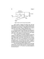
Figure 9a shows a full cycle of such loading; Figure 9b shows the corresponding steady-
state displacement response computed using the short bearing model data represented in
Figure 8b.
Computations using essentially the same program with data for more accurate film models
show qualitatively similar results.
12,13,25,26
Extensive comparisons
20
support continued use
of the short-bearing model in correlation studies. Further applications of orbit analysis,
parametric studies, corresponding design criteria (minimum film thickness, maximum film
pressure, power dissipation, etc.), and their correlation with failure modes and field expe-
rience are discussed elsewhere.
13,20-22,26,27
Parametric Studies
Mobility method results for four-stroke engines (automotive Otto and Diesel, and industrial
Diesel) are summarized elsewhere.
20
In all cases, firing loads have a minor (less than 20%)
effect on predicted minimum film thicknesses so long as the maximum bearing load due to
Volume II133
FIGURE 9.Connecting-rod bearing polar diagrams.
12,13,15
(a) Journal loading cycle (four-stroke combustion),
and (b) journal displacement cycle (short-bearing film model).
121-137 4/11/06 12:28 PM Page 133
Copyright © 1983 CRC Press LLC
firing alone is no more than about seven times the maximum bearing load due to inertia
alone. For a particular medium-speed Diesel this means that firing loads have negligible
effect on predicted film thicknesses above about 300 rev/min.
Thus for many higher-speed engines, firing loads have very little effect on minimum film
thickness and can be reasonably ignored in preliminary design computations. Figure 10
13,21
summarizes 120 different minimum film thickness predictions for connecting-rod bearings
134 CRC Handbook of Lubrication
FIGURE 10. Connecting-rod bearing under inertia loading: minimum film
thickness/maximum journal displacement.
13
121-137 4/11/06 12:28 PM Page 134
Copyright © 1983 CRC Press LLC
loaded by inertia forces alone. The omission of firing loads allows convenient characterization
of results by the dimensionless parameters shown. (For film models other than the short-
bearing, both upper and lower graphs will be weakly dependent on slenderness ratio L/D.)
Thus preliminary design guidance is available through Figure 10 without resort to computa-
tion.
The intermediate value
0
given by the lower graph of Figure 10 can be interpreted as
the steady-state response to a steadily rotating inertia load applied to a steadily rotating
journal in a nonrotating sleeve. The final value
max
given by the upper graph of Figure 10
reflects the further effects of reciprocating inertia and engine geometry on extremes of
periodic response.
Field Experience
Film thickness predictions and field experience for about 60 practical connecting-rod
bearings,
20
together with experiences from several other sources,
22
suggest the danger levels
in Table 1. Main bearings are understood to be a bit more tolerant in smaller sizes.
Noting the uncertainties involved, exceeding these values in no sense guarantees success;
though believed to be representative, they are offered for information only. It is also inter-
esting to compare these limiting values of predicted oil film thickness with peak-to-valley
estimates of surface finish.
∋
∋
Volume II 135
Table 1
DANGER LEVELS FOR FILM THICKNESSES
PREDICTED BY SHORT BEARING FILM MODEL
FOR CONNECTING-ROD BEARINGS
13
D(typical) h(dangerous)
mm(in.) µm(µin.)
Automotive (Otto) 50(2) 1.0 (40)
Automotive (Diesel) 75—100 (3—4) 1.75 (70)
Industrial (Diesel) 250(10) 2.5 (100)
121-137 4/11/06 12:28 PM Page 135
Copyright © 1983 CRC Press LLC
NOMENCLATURE
A Area [L
2
]
I Area polar moment [L
4
]
L Length [L]
B Breadth [L]
D Diameter [L]
R Radius [L]
C Radial clearance [L]
U Surface tangential velocity [LT
–l
ω Surface angular velocity [T
–1
]
µ Film viscosity [FL
–2
T]
h Film thickness [L]
P Film pressure [FL
–2
]
P Dimensionless pressure ratio [ – ]
q Outflow rate [L
3
T
–1
]
Q Dimensionless outflow ratio [ – ]
F Film force [F]
K Dimensionless film force (stiffness) [ – ]
W Dimensionless film force (impedance) [ – ]
M Dimensionless velocity (mobility) [ – ]
J Dimensionless impulse [ – ]
e Eccentricity [L]
Dimensionless eccentricity ratio [ – ]
r Crank radius (throw) [L]
ᐉ
Rod length [L]
m
rec
Reciprocating mass [M]
m
rot
Rotating mass [M]
t Time [T]
r, θ Coordinates [L,–]
x,y Coordinates [L,L]
x′,y′ Coordinates [L,L]
X,Y Coordinates [L,L]
· Time derivative [T
–1
]
* Special value
– Average value
∋
136 CRC Handbook of Lubrication
121-137 4/11/06 12:28 PM Page 136
Copyright © 1983 CRC Press LLC
REFERENCES
1. Gross, W. A., Matsch, L. A., Castelli, V., Eshel, A., Vohr, J. H., and Wildmann, M., Fluid Film
Lubrication, John Wiley & Sons, New York, 1980, chap. 8.
2. Warner, P. C., Static and dynamic properties of partial journal bearings, J. Basic Eng., 85, 247, 1963.
3. Booker, J. F. and Rohde, S. M., Toward the Optimum Side Leakage Correction Factor, Research Rep.,
General Motors Research Laboratories, Warren. Mich., in press.
4. Archibald, F. R., Squeeze films, in Standard Handbook of Lubrication Engineering, O’Connor, J. J.,
Ed., McGraw-Hill, New York, 1968, chap. 7.
5. Moore, D. F., A review of squeeze films, Wear, 8, 245, 1965.
6. Moore, D. F., Principles and Applications of Tribology, Pergamon Press, Oxford, 1975, 113.
7. Hays, D. F., Squeeze films for rectangular plates, J. Basic Eng., 83, 579, 1961.
8. Goenka, P. K. and Booker, J. F., Spherical bearings: stalic and dynamic analysis via the finite element
method, J. Lubr. Technol., 102, 308, 1980.
9. Booker, J. F., Dynamically loaded journal bearings: maximum film pressure, J. Lubr. Technol., 91, 534,
1969.
10. Childs, D., Moes, H., and van Leeuwen, H., Journal bearing impedance descriptions for rotordynamic
applications (with discussion by Booker, J. F.), J. Lubr. Technol., 99, 198, 1977.
11. Booker, J. F., Dynamically loaded journal bearings: mobility method of solution, J. Basic Eng., 87, 537,
1965.
12. Booker, J. F., Dynamically loaded journal bearings: numerical application of the mobility method. J. Lubr.
Technol., 93, 168 and 315, 1971.
13. Booker, J. F., Design of dynamically loaded journal bearings, in Fundamentals of the Design of Fluid
Film Bearings, Rohde, S. M., Maday, C. J., and Allaire, P. E., Eds., American Society of Mechanical
Engineers, New York, 1979, 31.
14. Barwell, F. T., Bearing Systems, Oxford University Press, Oxford, 1979, 261.
15. Campbell, J., Love, P. P., Martin, F. A., and Rafique, S. O., Bearings for reciprocating machinery:
a review of the present slate of theoretical, experimental and service knowledge (with discussion by Booker,
J. F.), Proc. Inst. Mech. Eng., 182(3A), 51, 1967.
16. Blok, H., Full journal bearings under dynamic duty: impulse method of solution and flapping action (with
discussion by Booker, J. F.), J. Lubr. Technol., 97, 168, 1975.
17. Hays, D. F., Squeeze films: a finite journal bearing with a fluctuating load (with discussion by Phelan,
R. M.), J. Basic Eng., 83, 579, 1961.
18. Donaldson, R. R., Minimum squeeze film thickness in a periodically loaded journal bearing, J. Lubr.
Technol.
, 93, 130, 1971.
19. Booker, J. F. Analysis of Dynamically Loaded Journal Bearings: The Squeeze Film Considering Cavitation,
Ph.D. thesis, Cornell University, Ithaca, N.Y., 1961.
20. New, N. H., The use of computer design techniques applied to IC engines, presented at Int. Symp. on
Plain Bearings, S
`
trbské Pleso, Czechoslovakia, October 24 to 26, 1972.
21. Martin, F. A. and Booker, J. F., Influence of engine inertia forces on minimum film thickness in con-
rod big-end bearings, Proc. Inst. Mech. Eng., 181, 30, 1967.
22. Warriner, J. F., Factors affecting the design and operation of thin shell bearings for the modem diesel
engine, Diesel Engines for the World, Whitehall Press, England, 1977/78, 13-23.
23. Booker, J. F., A table of the journal-bearing integral, J. Lubr. Technol., 87, 533, 1965.
24. Moes, H. and Bosnia, R., Mobility and impedance definitions for plain journal bearings, J. Lubr. Technol.,
103, 468, 1981.
25. Goenka, P. K., Analytical curve fits for solution parameters of dynamically loaded journal bearings, ASME
PaperNo. 83-Lub-33, J. Tribology, in press.
26. Martin, F. A., Developments in engine bearings design, in Tribology International, 16, 147, 1983, from
Tribology of Reciprocating Engines, (Proc. 9thLeeds-Lyon Symp. on Tribology, Leeds, England, September
1982). Dowson, D., Taylor, C. M., Godet, M., and Berth, D., Eds., Butterworths, 1983, 9.
27. Hollander, M. and Bryda, K. A., Interpretation of engine bearing performance by journal orbit analysis,
Paper 830062, presented at SAE International Congress, Detroit, Mich., February 28 to March 4, 1983.
Volume II 137
121-137 4/11/06 12:28 PM Page 137
Copyright © 1983 CRC Press LLC
ELASTOHYDRODYNAMIC LUBRICATION
Herbert S. Cheng
INTRODUCTION
Elastohydrodynamic lubrication (EHL) applies to conditions where surface deformation
and hydrodynamic action both play important roles. The most prominent example of EHL
is the Hertzian contact in rolling element bearings, gears, and cams where surface deformation
often exceeds the mean film thickness.
In elastohydrodynamic contacts, lubrication effectiveness is often measured by the average
film thickness separating the asperities between two surfaces. Good lubrication performance
is usually achieved when the mean separation approaches or exceeds three times the composite
rms value of surface roughness. In this full-film region, overall performance can usually be
predicted by EHLtheories considering smooth boundaries. While full-film EHLtheories are
useful in predicting performance, partial-film EHL(Figure 1) relations are required in
forecasting conditions for failure by pitting, scuffing, or wear.
Effects of surface deformation in sliding journal and thrust bearings can also be regarded
as EHLproblems and will be discussed briefly. Finally, application of EHLtheories in roller
and ball bearings, spur gears, helical gears, and cams will be reviewed.
FULL-FILM EHL
After two decades of intensive efforts, characteristics of full-film EHLare now reasonably
well understood. The principal features were first revealed in two-dimensional analyses for
line contacts. Later, three-dimensional analyses showed additional features in point or el-
liptical contacts.
Line Contacts
Line contact geometry applies to cases which correspond to two cylinders in contact:
rolling-element bearings, uncrowned spur and helical gears, etc. Most EHLanalyses have
used this geometry both because it is easiest to analyze and because it reveals basic features
common in more complicated contacts.
Film Thickness
Classical lubrication theories for rigid rollers are of interest to show their inadequacy in
predicting film thickness for EHLcontacts. Two rigid rollers are equivalent to a rigid roller
on a flat plate, shown in Figure 2. The lubricant transported at any point along the film is
(1)
where p, h, u
1
, u
2
, and µ are pressure, film thickness, surface velocity of roller 1 and 2,
and viscosity, respectively.
Let the lubricant flow rate be 1/2 (u
1
+ u
2
)h*, where h* is the gap where dp/dx is zero.
Continuity of flow gives
(2)
Volume II 139
Copyright © 1983 CRC Press LLC
where µ
o
is the ambient viscosity and α the pressure-viscosity coefficient. By introducing
a “reduced pressure” q = (1 – e
–αp
)/ α, Equation 3 can be simplified to
(4)
Equation 4 can be solved for q, which lead to p and the load capacity. Improvement in film
thickness was still far from enough to suggest a full-film hypothesis.
Ertel-Grubin
2
provided the first convincing evidence of full-film EHL by solving Equation
4 for a Hertzian shape shown in Figure 3. They determined h
o
, the inlet film thickness, for
the reduced lubricant pressure q to reach 1/α (or p →∞) at x → –b, the entrance of the
Hertzian conjunction. Once e–
αp
approaches zero, µ becomes very large in the conjunction.
A very minute change in conjunction film thickness would cause an enormous change in
pressure. Therefore, for heavily loaded contacts, the gap in the conjunction is practically
uniform. Equation 4 was solved using the Hertzian inlet film profile:
(5)
where 1/E = 1/2 [(1 − v
2
1
)/E 1 + (1 − v
2
2
)/E
2
] x
–
= x/b, and w = load per unit width.
Empirical fitting yields the following equation which gives film thicknesses one or two
orders of magnitude higher than rigid roller theories:
(6)
where G = αE, U = µ
o
u/ER, W = w/ER, and R = R
1
R
2
/(R
1
+ R
2
).
Ertel-Grubin’s formula for predicting h
o
holds well for a reasonably wide range of con-
ditions. It becomes less accurate when G < 1000 (lubricant with a small pressure-viscosity
dependence or material of low modulus) and when W becomes small (<10
–5
). Solution for
h
o
for the full range of G from 0 to 5000 can be found in References 3, 4, and 5. Lubricant
compressibility was included.
When U is very large, reduction of viscosity due to inlet shear heating requires solving
the energy equation simultaneously with Equation 4 in the inlet region.
6-8
Results led to a
Volume II 141
FIGURE 3. Inlet geometry of Grubin-lype EHL line
contact.
Copyright © 1983 CRC Press LLC
thermal reduction factor, φ
T
, which can be multiplied by the Frtel-Grubin film thickness
for the actual h
o
. With φ
T
, varying slightly with Wand lubricant pressure G, Figure 4 gives
a first approximation.
7
Starvation introduced another reduction factor which is a function of the distance between
the inlet film meniscus and the entrance edge of the Hertzian conjunction as indicated in
Figure 5.
9,10
For rollers lubricated with an initial charge only, film thickness would be
gradually reduced to about 0.71 of the fully flooded initial value.
10
Measurements of film thickness in line contracts have been reviewed by Archard.
11
The
first confirmation of Ertel-Grubin’s film prediction was due to Crook,
12
who measured the
capacitance between two discs. The second significant film measurement method was de-
veloped by Sibley and Orcutt
13
using X-ray techniques. Optical measurements were made
by Wymer and Cameron.
14
Film Shape and Pressure Distribution
For a detailed film thickness and pressure distribution, the following coupled Reynolds
and deformation equations must be solved:
(7)
(8)
where x* is the coordinate at which the lubricant film terminates. At x = x*, h = h*, dp/
dx = 0.
142CRC Handbook of Lubrication
FIGURE 4. Thermal reduction factor, where Q
m
= thermal parameter, µ
c
= ambient lubricant viscosity, u =
rolling velocity, T
o
= ambient temperature, k
f
= lubricant thermal conductivity, and δ = temperature viscosity
coefficient in the empirical relation µ = µ
o
e
–δ
(T — T
o
).
Copyright © 1983 CRC Press LLC