Handbook of Lubrication Episode 2 Part 9 pdf
Bạn đang xem bản rút gọn của tài liệu. Xem và tải ngay bản đầy đủ của tài liệu tại đây (772.15 KB, 15 trang )
runs off the gear case, it can be collected in troughs and directed to bearings. For very slow
gearing using heavy oil, it may be necessary to use scrapers to remove oil from the sides
of the gear rim for use as a bearing lubricant. If for other reasons the sump oil level is
higher than required for gearing lubrication, an oil pan can be used to limit the amount of
oil that the gear contacts. The flow of oil into the pan is controlled by small holes below
the oil level to eliminate excessive churning and improve efficiency. Oil pans are recom-
mended for gears with pitch line velocities over 13 m/sec (2500 ft/min) and work well for
slow- and moderate speed gearing with pitch line velocities up to 18 m/sec (3500 ft/min).
Higher speed gearing will tend to centrifugally throw off most of the oil before it gets into
mesh. The lighter oil generally used with high-speed gearing tends to compound the problem.
Higher power losses caused by churning also tend to make splash lubrication impractical
for high-speed gearing.
Another common means for applying easy flowing liquid lubricants is a force-fed system
(Figure 6). In this system oil is taken from the gear case, pumped through a filter, heat
exchanger, and pressure relief valve, and delivered back to the unit under pressure. The
amount of oil delivered to the bearings can be set by an orifice or other flow-control device.
Oil is applied to the gear mesh by spray nozzles in a manifold.
Frictional heat generation may range, typically, from 0.5 to 1% of the transmitted horse-
power per mesh for spur or helical gears. Sump capacity and oil flow rate can be established
for a desired sump temperature (95°C maximum is recommended for petroleum based lu-
bricants). Inlet oil temperature and flow rate should be selected to maintain a suitable
operating oil viscosity in the mesh. For enclosed, industrial gears, inlet oil temperatures of
38 to 54°C and temperature rises in the mesh of 17 to 28°C are typical for circulating systems.
The amount of oil is controlled by the size of the nozzles and oil pressure. Oil velocity
must be sufficient to get the oil down into the tooth space before windage and tooth rotation
554 CRC Handbook of Lubrication
Table 7
RECOMMENDED AGMALUBRICANTS (FOR
INTERMITTENTMETHODS OFAPPLICATION
LIMITED TO 1500 FT/MIN (8 M/SEC) PITCH LINE
VELOCITY)
a
Note: AGMA Viscosity number recommendations listed above refer to gear oils
shown in Table 5.
a
Feeder must be capable of handling lubricant selected.
b.
Ambient temperature is temperature in vicinity of the gears.
c
Greases are sometimes used in mechanical spray systems to lubricate open
gearing. A general purpose EP grease of number 1 consistency (NGLI) is
preferred. Consult gear manufacturer and spray system manufacturer before
proceeding.
d
Diluents must be used to facilitate flow through applicators.
From Standard AGMA 251.02, Lubrication of Industrial Open Gearing, Amer-
ican Gear Manufacturers Association, Arlington, Va., November 1974. With
permission.
539-564 4/10/06 5:02 PM Page 554
Copyright © 1983 CRC Press LLC
deflect and block the spray. Spray nozzle pressures of 15 to 50 psi are usually adequate for
industrial gearing. Advantages of this system are that the oil delivered is of controlled
quantity, cleanliness, and temperature. The oil spray can flush wear particles and debris
from the gear mesh. Heat will also be carried away with the excess lubricant. In high-speed
gearing where excessive lubricant in the mesh is not desirable, high-flow sprays should be
directed at the gear tooth surfaces as they leave mesh for maximum cooling. Low-flow
sprays should be directed at the teeth just before mesh for maximum lubrication. Screening
is sometimes installed in high-speed gear cases above the sump oil level to minimize the
windage effects on oil foaming. There are no practical limiting speeds for force-fed systems.
Heavy open gear compounds are generally applied by paddle or brush, slush pan or
automatic lubricator. The manual paddle or brush method is crude, with the distribution of
lubricant being erratic.
The slush pan method utilizes a pan filled with lubricant into which the gear dips. The
lubricant is then carried into mesh where excess material is squeezed out and drops back
into the pan. The method provides for continuous lubrication and applies lubricant evenly
across the entire tooth. It can be used with gearing with pitch line velocities up to 10 m/
sec (2000 ft/min).
Volume II 555
FIGURE 5. Splash lubrication system.
539-564 4/10/06 5:02 PM Page 555
Copyright © 1983 CRC Press LLC
556 CRC Handbook of Lubrication
Table 8
RECOMMENDED QUANTITIES OF LUBRICANT
(FOR INTERMITTENT METHODS OF APPLICATION WHERE PITCH LINE VELOCITY DOES NOT
EXCEED 1500 FT/MIN (8 M/SEC) FOR AUTOMATIC, SEMIAUTOMATIC, HAND SPRAY, GRAVITY
FEED, OR FORCED DRIP SYSTEMS)
539-564 4/10/06 5:02 PM Page 556
Copyright © 1983 CRC Press LLC
Volume II 557
a
The spraying time should equal the time for 1 and preferably 2 revolutions of the gear to ensure complete coverage. Periodic inspections should
be made to ensure that sufficient lubricant is being applied to give proper protection.
b
Four hours is the maximum interval permitted between applications of lubricant. More frequent application of smaller quantities is preferred.
However, where diluents are used to thin lubricants for spraying intervals must not be so short as to prevent diluent evaporation.
From Standard AGMA 251.02, Lubrication of Industrial Open Gearing, American Gear Manufacturers Association, Arlington, Va., November
1974. With permission.
539-564 4/10/06 5:02 PM Page 557
Copyright © 1983 CRC Press LLC
will remove some material from the area of hardest contact and spread the load over more
of the face-width. These minor modifications from light, initial wear improve the gear tooth
conformity and make it possible for the gears to operate under full-load with less chance of
damage. Initial wear can be intentionally induced by using a lighter lubricant for a break-
in period. How light a lubricant depends on the initial load and the desired rate of wear.
Extreme caution should be exercised and tooth surfaces should be examined frequently to
prevent rapid, destructive wear. Under normal operating conditions, initial wear may occur
and stop by itself when sufficient conformity has been achieved to support the load.
Moderate wearwould result from increased rate of surface material removal due to more
significant surface irregularities, gear tooth misalignment, dynamic load pulsations, insuf-
ficient lubricant viscosity, or any conditions that would cause the gearing to operate under
conditions of boundary of mixed film lubrication. It could also be caused by abrasive material
in the lubricant. This wear would probably not stop by itself but would continue, slowly,
over a long period of time. Depending on the anticipated life of the gearing, this type of
wear may, or may not be acceptable.
Heavy wearwould involve rapid removal of surface material, destroying the tooth form,
and hindering the smooth operation of the gear set. This can be caused, for example, by
operating the gears without any lubricant or under conditions of heavy overload or severe
misalignment of contacting tooth surfaces. This destruction of the tooth form will lead to a
very short-service life for the gear set if the causes are not found and corrected. Excessive
loading is the most common cause of rapid wear, although lubrication receives considerable
attention since it is easier to change.
Examining a gear set to determine the cause of excessive wear or failure is not always
an easy task. The final mode of failure may be the result of previous wear mechanisms of
an entirely different nature. Adiscussion of several common forms of wear may help to
establish the probable sequence of events leading to excessive wear or failure in a gear set.
Breakage(Figure 7) — Catastrophic tooth failure is caused by a gear tooth being subjected
to loads and, consequently, bending stresses in excess of the endurance limit of the gear
material. This will cause a tooth or portion of a tooth to break away. The breakage usually
starts as a crack which propagates with repeated load cycles showing a typical fatigue failure.
Occasionally, a tooth may fail from a single-load cycle. This would not show a fatigue type
failure. Breakage can be caused by shock loads, loads induced by high vibration, large
pieces of debris passing through the gear mesh, or by misalignment causing the tooth load
to be carried by a small portion of the face-width. Obviously, lubrication is not a factor and
the mechanical defects must be located and corrected.
Pitting (Figure 8) — This common form of surface fatigue occurs when small localized
high spots on the tooth surface are overstressed due to high-unit loading. When this occurs,
small subsurface cracks are formed which propagate to the surface after repeated cycles.
When an area of material is no longer supported, it leaves the surface of the tooth creating
a small depression or pit. Small pits may form in a new gear set as high spots from machining
are removed. Once enough load bearing surface is in contact, pitting may stop and the
surface will begin to “polish over”. If this takes place, the pitting is considered “initial”
and is not harmful. If the pitting continues to spread, leaving increasingly less surface to
carry the load, it is considered progressive. If the condition is not corrected, material will
continue to be removed from the tooth until, eventually, tooth breakage may occur. This is
not a lubrication failure. The condition can be caused by misalignment of the gear teeth,
causing a relatively small area to carry the load with resultant high stresses. Gear material
too soft for the application or operating loads greater than those for which the gearing was
designed can also cause pitting. The use of a heavier oil may help spread the load over a
larger area, but lubricant adjustments will generally give little, if any, help. The use of some
EP lubricants or additives may extend the life of the gearing but will not correct the problem.
Volume II 559
539-564 4/10/06 5:02 PM Page 559
Copyright © 1983 CRC Press LLC
Spalling (Figure 9) — This mechanism is the same as for pitting. Large flakes or chips
may be removed from through hardened or case hardened gears from subsurface flaws or
stresses caused by improper heat treatment. The joining of pits as the metal between them
is removed is also a form of spalling. Again, this is not a lubrication problem. It is a result
of material defects, excessive load, or other application problems.
Plastic flow (Figure 10) — This type of wear represents gear tooth surface deformation
caused by heavy loads stressing the surface material beyond its elastic limit. Usually occurring
in softer metals, the surface material may be extruded out along the ends of the teeth and
along the tip causing fins to form. Prominent ridges at the pitch line or depressions in the
dedendum may also be indications of this type of wear. If the wear is caused by high
vibration or shock load, a heavier lubricant may cushion the load somewhat. However, this
type of wear is a material failure and lubricant changes will not correct it.
Scratching (Figure 11) — This is a type of abrasive wear. When hard particles, which
are larger than the oil film thickness separating the gear teeth, pass through the gear mesh,
they scratch the gear tooth surfaces in the direction of sliding. These particles can be dirt,
sand, casting scale, welding slag, gear or bearing material, or any debris which finds its
way into the lubrication system. The material can be airborne and enter through openings
in poorly fitting enclosures or uncovered inspection ports. It may be the result of poorly
cleaned housings or rotating elements prior to assembly. The debris may also be from wear
within the gear unit. Laboratory analysis can generally indicate the type of particle material.
Increasing the lubricant viscosity will increase the film thickness and may ease the problem,
but not cure it. Abetter solution is to remove the abrasive particles through finer lubricant
filtration, improved maintenance, etc. Once the problem is corrected, gear surface deteri-
oration will cease.
Scoring (Figure 12) — When small local high spots or asperities on mating gear tooth
surfaces break through the oil film and cause metal-to-metal contact, they may weld together
Volume II561
FIGURE 9.Spalling. (From Standard AGMA110.4, Nomenclature of Gear Tooth Failure Modes, American
Gear Manufacturers Association, Arlington, Va., August 1980. With permission.)
539-564 4/10/06 5:02 PM Page 561
Copyright © 1983 CRC Press LLC
REFERENCES
1. Fowle, T. I., Gear lubrication: relating theory to practice, Lubr. Eng., 32, 17, 1976.
2. Fowles, P. E., EHL film thickness — practical significance and simple computation. Lubr. Eng., 32, 166,
1975.
3. Ku, P. M., Gear failure modes — importance of lubrication and mechanics, ASLE Trans., T19, 239, 1976.
4. Wedeven, L. D., What is EHD?, Lubr. Eng., 31, 291, 1975.
5. Lipp, L. C., Solid lubricants — their advantages and limitations, Lubr. Eng., 32, 574, 1976.
6. Hersey, M. D., Gear lubrications, in Theory and Research in Lubrication, John Wiley & Sons, New York,
1966. chap. 11.
7. Root, D. C., Selecting the right gear oil, Lubr. Eng., 32, 8, 1976.
8. Standard AGMA 250.04, Lubrication of Industrial Enclosed Gear Drives, American Gear Manufacturers
Association, Arlington, Va., 1974.
9. Standard AGMA 251.02, Lubrication of Industrial Open Gearing, American Gear Manufacturers Associ-
ation, Arlington, Va., November 1974.
10. Standard AGMA 110.4, Nomenclature of Gear Tooth Failure Modes, American Gear Manufacturers As-
sociation, Arlington, Va., August 1980.
564 CRC Handbook of Lubrication
539-564 4/10/06 5:02 PM Page 564
Copyright © 1983 CRC Press LLC
MECHANICALSHAFTCOUPLINGS
Michael M. Calistrat
INTRODUCTION
Amechanical shaft coupling is that part of a machine which transmits torque from one
shaft to another. There are significant differences between different types of mechanical
shaft couplings, and for a better understanding of their working principles we should first
categorize them. First, shaft couplings can be divided into rigid and flexible couplings.
Rigid couplings — usually in the form of a long collar or a couple of bolted flanges,
perform the torque transmission in the most efficient way. Unfortunately they can be used
only when the two connected shafts are perfectly aligned. Rigid couplings do not require
lubrication.
Flexible couplings — transmit torque without slip, and accommodate misalignment be-
tween the driving and driven shafts.
1
They too can be divided into two categories depending
on the means used to accommodate the misalignment: couplings using the flexing of one or
more of their components, and couplings that use sliding of two or more of their components.
Some couplings use both of these methods in their design. The couplings that accommodate
misalignment only through flexing do not require lubrication and fall outside the scope of
this manual. Couplings that use sliding for accommodating misalignment must be lubricated
in order to minimize wear.
Nonlubricated, or dry, couplings use either an elastomer or one or more thin metal disks
which flex in order to accommodate misalignment. Since useful life of these flexing elements
is limited by such factors as fatigue, fretting corrosion, or elastomer aging, they have to be
replaced periodically. Besides that, elastomer couplings are usually larger and heavier than
lubricated couplings with similar ratings. Hence, the need for lubrication is compensated in
many instances by less maintenance and/or smaller size. Dry couplings are used mainly in
fractional and low-horsepower applications ( < 200 kWor 300 hp); lubricated couplings
are particularly popular in large-horsepower applications.
DESCRIPTION
Although there is an endless variety of lubricated shaft couplings, three designs are most
frequently found: the gear, chain, and the steel grid couplings, shown in Figures 1 to 3,
respectively.
GearCouplings
The gear coupling (Figure 1) has five major components: two hubs, two sleeves, and in
some cases a spacer (not shown). It also has a number of bolts, nuts, lockwashers, and two
or more seals. The spacer is omitted when the separation between the connected shafts is
small. The hubs have a row of external teeth with involute profile; the sleeves have matching
internal teeth. Each gear mesh acts as a spline; to accommodate misalignment, the external
teeth are slightly thinner than the space between the internal teeth. The space thus generated
between the teeth is called the backlash and it allows the hub teeth to assume an angular
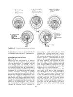
position, as shown in Figure 4.
The need for lubrication can be understood by considering the sliding motion of the hub
teeth on the sleeve teeth. Figure 5 illustrates a section through half of a gear coupling, i.e.,
a hub and a sleeve. Because the coupling is misaligned, the centerline of the hub teeth, BB,
does not coincide with the centerline of the sleeve teeth, AA. Hence, the lower hub tooth
Volume II 565
565-579 4/10/06 5:06 PM Page 565
Copyright © 1983 CRC Press LLC
of coupling is used in applications having short shaft separation. The principle of operation
is similar to the gear couplings when considering the sprockets as hubs and the double-row
chain as the two sleeves. Only when used with a cover can the chain couplings benefit from
the effect of centrifugal forces in the lubricant. From a torsional point of view, the chain
couplings are less stiff than gear couplings.
Steel Grid Couplings
Steel grid couplings are even more flexible, torsionally, than chain couplings. They also
operate similarly to a gear coupling, having two toothed hubs and a sleeve in a form of a
convoluted spring steel band. Because of the special profile of the teeth, thesteel grid flexes
under torque, as shown in Figure 7.
To accommodate misalignment the hub teeth slide over the steel grid just as in a gear
coupling, Asplit cover is always provided in order to retain both the steel grid and the
lubricant within the coupling. Similar to chain couplings, the steel grid couplings can be
used only when the gap between the shafts is small.
DESIGN AND MATERIALS
The GearCoupling
The three major types of gear couplings are
1. Standard — medium speeds and medium-torque couplings
2. Spindle — low speeds and high-torque couplings
3. High performance — high speeds and medium-torque couplings
Volume II569
FIGURE 6. Centrifugal forces in couplings.
565-579 4/10/06 5:06 PM Page 569
Copyright © 1983 CRC Press LLC
(Figure 9) and the elastomer seal (Figure 10). The main difference between the two types
of couplings in Figures 9 and 10 is the lubricant capacity; for couplings with identical
flanges, the metal seal coupling has a larger lubricant reservoir than the elastomer seal
coupling. Although physically possible, couplings with different lubricant capacities should
not be bolted together because one half can become starved of lubricant and wear rapidly.
Spindle Couplings
Spindle couplings are used in special applications that require high-torques and high-
misalignment capability, but at relatively low speeds. Atypical example is the rolling mill
in steel mills. To be able to transmit high torques, spindle couplings are made of high-
strength alloy steels, and the teeth have a hardened surface obtained usually through nitriding
or carburizing. To further increase the strength of the teeth, spindle couplings have fewer
teeth than standard couplings, usually 40 teeth. To accommodate high misalignments, all
spindle couplings use barreled teeth with a relatively small radius of curvature. Another
design characteristic of spindle couplings is a quite large distance between the driving and
driven shafts, and the couplings use a “floating shaft” to bridge this distance.
High-Performance Couplings
In many cases these couplings (Figure 11) operate at speeds in excess of 10,000 rpm and
Volume II571
FIGURE 8. Typical force patterns in gear couplings.
565-579 4/10/06 5:06 PM Page 571
Copyright © 1983 CRC Press LLC
COUPLING LUBRICATION
Whether the coupling is of the gear, chain, or steel grid type, it accommodates mis-
alignment through a sliding motion between the hub (or sprocket) teeth and the mating element
(sleeve, chain, or steel grid). The torque that the coupling transmits generates a force between
these mating surfaces, and the rotation combined with the misalignment generate a rapid
oscillatory motion. The forces and the motion tend to wipe off the lubricant from the contact
surfaces. As the hub tooth slides in one direction, however, the lubricant has a chance to
wet the area left uncovered behind the tooth. To do that, the lubricant has to work against
two elements: its own viscosity and the very short time available during one cycle. The
teeth would operate dry if it was not for the centrifugal forces created by the rotation of the
coupling. The centrifugal forces generate a pressure in the lubricant annulus high enough
to force the lubricant in the spaces between the teeth. The pressure in the lubricant can be
determined by the formula:
where ρ = specific mass, ω = angular velocity (rad/sec), R
1
= major radius of the annulus,
and R
2
= minor radius of the annulus.
Example:For a coupling of Figure 4, with a 152-mm (6 in ) pitch diameter, operating at
3600 rpm, the pressure generated by the centrifugal forces is 410 kPa (60 psi).
Methods of Lubrication
The two basic methods of lubrication are batch and continuous oil flow. Only gear
couplings use the latter. Whether one or the other method should be used depends primarily
on the capability of the coupling to dissipate the heat generated by friction. When a coupling
operates under a horseshoe-type cover, the circulation of air induced by the rotational speed
provides all the cooling the coupling needs. When the couplings operate in a sealed enclosure,
as is the case with most high-performance couplings, special cooling must be provided,
usually by a continuous flow of oil.
A batch-lubricated coupling can be filled with either oil or grease. The main problem
with oil-filled couplings is that the seals tend to allow the oil to drip away under static
conditions and the coupling would then operate dry when it is restarted. Only one type of
gear coupling is designed with a labyrinth seal so that it can operate with oil. Grease is
much easier to seal in a coupling, and it is the most frequently recommended lubricant. It
is interesting that when the coupling is operating, centrifugal forces prevent the lubricant
from escaping; seals are required both to prevent dirt from penetrating into the coupling and
to retain the lubricant when the coupling is not operating.
Grease as a Coupling Lubricant
Because the gear, chain, and grid couplings are similar in the manner through which they
accommodate misalignment and transmit torque, a grease that is satisfactory for one type
generally gives good results for the others. Nevertheless, various manufacturers unfortunately
have quite different recommendations for lubricants and a common denominator is difficult
to find.
The most important conclusion of one study is that the wear rate of a type gear coupling
is greatly influenced by the viscosity of the base oil of the grease: the higher the viscosity,
the lower the wear rate.
2
This phenomenon might explain why many coupling manufacturers
prefer to recommend a NLGI No. 2 grease over a No. 1 or 0. However, the penetration of
a grease seldom reflects its base oil viscosity, which generally should exceed 198 cSt at
40°C for optimum performance.
p =
ρ
ω
2
(R
1
2
− R
2
2
) / 2
574 CRC Handbook of Lubrication
565-579 4/10/06 5:07 PM Page 574
Copyright © 1983 CRC Press LLC
Especially demanding conditions are the high centrifugal forces imposed on a grease in
a coupling. Even under normal gravity, greases tend to bleed some oil; under the high G
level in couplings, the stratification of additives, soap, and oil takes place rapidly and in
many cases can be total.
3,4
Agrease which is separated into oil and soap is no longer suitable
for coupling lubrication. First, the oil will then leak out of the coupling, particularly when
the coupling is at a standstill. Second, the centrifugal force will force the denser soap and
fillers away from the axis of rotation and eventually coat the inside surfaces of the coupling
housings (or sleeves). In Figures 1, 2, and 3 one can see that the hub teeth are located close
to the housings, which is done to reduce the tangential forces on the teeth. The soap separated
from the grease under the influence of centrifugal forces will surround the torque transmitting
elements, whether they are gear teeth, chains or steel grids, and will prevent the oil from
lubricating the surfaces that are under sliding contact. Under these conditions, a coupling
can wear rapidly although it is full of grease. Hence, the resistance of a grease to separation
under centrifugal forces is an important factor in selecting a good lubricant for couplings.
A third factor which should be considered is the volumetric percentage of oil in the grease.
Under high-centrifugal forces, practically all the greases will eventually separate at a rate
which depends on various factors. Some of the soap will start flowing toward the torque-
carrying elements right after the coupling is started. The more soap a grease contains, the
higher are the chances that the hub teeth will be flooded by soap. It is better, then, to use
a grease that has a small percentage of soap or fillers.
Oil as a Coupling Lubricant
Oil lubrication is used almost exclusively in high-speed gear couplings. As mentioned
previously, the flow of oil is necessary primarily to remove the heat generated by friction.
5
The efficiency of a good-quality, high-performance gear coupling is excellent, usually better
than 99.9%. Since high-performance couplings can transmit high power, however, the
amount of power loss can be considerable. For instance, a coupling transmitting 20,000 hp
at 99.9% efficiency will absorb 15 kW, which it will transform into heat. If this heat is not
dissipated it will damage the coupling. The oil used for the lubrication and cooling of
couplings is taken from the lubrication system of the machines connected by the coupling.
In most cases this oil is a light turbine oil which is not a good coupling lubricant. To offset
this marginal lubrication, many high-performance couplings have nitrided teeth.
The high centrifugal forces present in a coupling do not affect the oil as long as it is a
homogeneous fluid; however, the oil not only has components which are added for the
purpose of enhancing its properties, but also has unwanted impurities. Under centrifugal
forces, some of the additives and most of the impurities are separated and retained within
the coupling.
When the quantity of sludge in a coupling becomes excessive, it will (1) impair axial
movement of one shaft with respect to the other, (2) corrode the teeth and accelerate their
wear rate, and (3) reduce or completely stop the flow of oil, with high temperatures and
high wear rates as a consequence.
Sludge can be of two types: a moist sludge with the appearance and consistency of a
NLGI No. 3 grease, or a dry sludge which is hard and crumbles like clay. Moist sludge is
caused by an accumulation of oil additives in the coupling, in particular silicone antifoam
compounds. Moist sludge is a lubricant and its only drawback is that it prevents oil from
circulating through the coupling. Dry sludge is caused by an accumulation of impurities
from the oil such as sand in the desert, or fertilizer near a chemical plant.
Whether sludge is moist or dry, the worst conditions are caused by water or other corrosive
liquids that might enter the coupling. Besides causing rapid wear and shortening coupling
life, corrosion can reduce the fatigue resistance of the coupling sleeves, which in turn can
Volume II 575
565-579 4/10/06 5:07 PM Page 575
Copyright © 1983 CRC Press LLC
result in catastrophic failures. The designers of lubrication systems are generally aware of
the problems that impurities in the oil can cause, and take necessary precautions to prevent
sludge accumulation in the couplings. Figure 12 illustrates an oil circuit that provides special
filtration for couplings. (API 671 recommends a 10-µm filter or less.)
Figure 13 illustrates a type of high-performance gear coupling which was developed so
that it will not retain sludge (known as damless or antisludge coupling). A large flow of oil
is required in order to maintain a sufficient level of lubricant in the coupling. It can be seen
that if the oil flow is insufficient, much of the tooth surface remains nonlubricated. Following
the manufacturers’ recommendations for the oil flow is very important for these types of
576 CRC Handbook of Lubrication
FIGURE 12. Oil circuit for continuous lubrication.
FIGURE 13. Oil flow in damless couplings.
565-579 4/10/06 5:07 PM Page 576
Copyright © 1983 CRC Press LLC
couplings. While in a dam-type coupling the lubrication is ensured by the oil annulus and
the oil flow is determined by the cooling requirements, the damless coupling needs a large
oil flow to be properly lubricated. In order to determine the nozzle size as a function of the
required flow and available pressure, the graph from Figure 14 can be used.
Lubricant Selection
Lubricant selection depends on the type of coupling and particularly on the application.
Volume II 577
FIGURE 14. Oil flow through nozzles. (Courtesy of Koppers Co., Inc., Pittsburgh, Pa.)
565-579 4/10/06 5:07 PM Page 577
Copyright © 1983 CRC Press LLC