Advanced Vehicle Technology Episode 2 Part 9 pdf
Bạn đang xem bản rút gọn của tài liệu. Xem và tải ngay bản đầy đủ của tài liệu tại đây (386.25 KB, 20 trang )
the epicyclic gear set does not operate in the fourth
quadrant even under full steering lock conditions.
9.5 Variable-ratio rack and pinion
(Fig. 9.37(a±d))
Variable-ratio rack and pinion can be made to
improve both manual and power assisted steering
operating characteristics. For a manual rack and
pinion steering system it is desirable to have a
moderately high steering ratio to provide an almost
direct steering response while the steering wheel is
in the normally `central position' for straight ahead
driving and for very small steering wheel angular
correction movement. Conversely for parking
manoeuvres requiring a greater force to turn the
steering wheel on either lock, a more indirect lower
steering ratio is called for to reduce the steering
wheel turning effort. However, with power assisted
steering the situation is different; the steering wheel
response in the straight ahead driving position still
needs to be very slightly indirect with a relatively
high steering ratio, but with the power assistance
provided the off-centre steering response for
manoeuvring the vehicle can be made more direct
compared with a manual steering with a slightly
higher steering ratio. The use of a more direct
low steering ratio when the road wheels are being
turned on either lock is made possible by the servo
action of the hydraulic operated power cylinder
and piston which can easily overcome the extra
tyre scrub and swivel-pin inclination resisting
force. The variable-ratio rack is achieved by having
tooth profiles of different inclination along the
length of the rack, accordingly the pitch of the
teeth will also vary over the tooth span.
With racks designed for manual steering the
centre region of the rack has wide pitched teeth
with a 40
flank inclination, whereas the teeth on
either side of the centre region of the rack have
a closer pitch with a 20
flank inclination. Con-
versely, power assisted steering with variable-ratio
rack and pinion (see Fig. 9.37(c)) has narrow
pitch teeth with 20
flank inclination in the cen-
tral region; the tooth profile then changes to a
wider pitch with 40
flank inclination away from
the central region of the rack for both steering
locks.
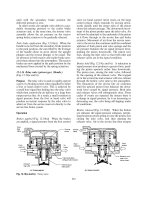
Fig. 9.36 (a±d) Principle of rear steering box mechanism
352
Pressure angle
20°
Pressure angle
40°
(a) Central rack teeth
(b) Off-centre rack teeth
Wide pitch (P)
Narrow
pitch (p)
Wide pitch (P)
(c) Variable-ratio tooth rack
Large p.c.d.
more direct
Transition
Small
p.c.d.
Transition
Large p.c.d.
30
25
20
15
5
0
480 180 120 60 30 0 30 60 120 180 480
Turning steering wheel to left
Turning steering wheel to right
Steering wheel and pinion rotation (deg)
(d) Rack and pinion movement ratio from lock to lock of the steering wheel
PP
R
r
Movement ratio
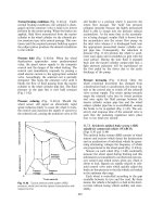
Fig. 9.37 (a±d) Variable ratio rack and pinion steering suitable for power assisted steering
353
With variable-ratio rack and pinion involute
teeth the rack has straight sided teeth. The sides
of the teeth are normal to the line of action,
therefore, they are inclined to the vertical at the
pressure angle. If the rack has narrow pitch `p'
20
pressure-angle teeth, the pitch circle diameter
(2R) of the pinion will be small, that is, the point
of contact of the meshing teeth will be close to the
tip of the rack teeth (Fig. 9.37(a)), whereas with
wide pitched `P' 40
pressure-angle tooth contact
between teeth will be near the root of the rack
teeth (Fig. 9.37(b)) so its pitch circle diameter (2R)
will be larger.
The ratio of steering wheel radius to pinion pitch
circle radius (tooth contact radius) determines the
movement ratio. Thus the smaller the pitch circle
radius of the pinion for a given steering wheel size,
the greater will be the movement ratio (see Fig.
9.37(d)), that is, a smaller input effort will be
needed to steer the vehicle, but inversely, greater
will be the steering wheel movement relative to the
vehicle road wheel steer angle.
This design of rack and pinion tooth profile can
provide a movement-ratio variation of up to 35%
with the number of steering wheel turns limited to
2.8 from lock to lock.
9.6 Speed sensitive rack and pinion power
assisted steering
9.6.1 Steering desirability
To meet all the steering requirements the rack and
pinion steering must be precise and direct under
normal driving conditions, to provide a sense of
feel at the steering wheel and for the steering wheel
to freely return to the straight ahead position after
the steering has been turned to one lock or the
other. The conventional power assisted steering
does not take into account the effort needed to
perform a steering function relative to the vehicle
speed, particularly it does not allow for the extra
effort needed to turn the road wheels when man-
oeuvring the vehicle for parking.
The `ZF Servotronic' power assisted steering is
designed to respond to vehicle speed requirements,
`not engine speed', thus it provides more steering
assistance when the vehicle is at a standstill or
moving very slowly than when travelling at speed;
at high speed the amount of steering assistance may
be tuned to be minimal, so that the steering
becomes almost direct as with a conventional man-
ual steering system.
9.6.2 Design and construction (Fig. 9.38(a±d))
The `ZF Servotronic' speed-sensitive power assisted
steering uses a conventional rotary control valve, with
the addition of a reaction-piston device which modi-
fies the servo assistance to match the driving mode.
The piston and rotary control valve assembly
comprises a pinion shaft, valve rotor shaft with
six external longitudinal groove slots, valve sleeve
with six matching internal longitudinal groove
slots, torsion bar, reaction-piston device and an
electro-hydraulic transducer. The reaction-piston
device is supported between the rotary valve rotor
and valve sleeve, and guided internally by the valve
rotor via three axially arranged ball grooves and
externally guided by the valve sleeve through a
multi-ball helix thread.
The function of the reaction-piston device is to
modify the fluid flow gap formed between the valve
rotor and sleeve longitudinal groove control edges
for different vehicle driving conditions.
An electronic control unit microprocessor takes
in speed frequency signals from the electronic
speedometer, this information is then continuously
evaluated, computed and converted to an output
signal which is then transmitted to the hydraulic
transducer mounted on the rotary control valve
casing. The purpose of this transducer is to control
the amount of hydraulic pressure reaching the
reaction-piston device based on the information
supplied to the electronic control unit.
9.6.3 Operation of the rotary control valve and
power cylinder
Neutral position (Figs 9.38(a) and 9.39(a)) With
the steering wheel in its central free position, pres-
surized fluid from the pump enters the valve sleeve,
passes though the gaps formed between the long-
itudinal groove control edges of both sleeve and
rotor, then passes to both sides of the power cylin-
der. At the same time fluid will be expelled via
corresponding exit `sleeve/rotor groove' control-
edge gaps to return to the reservoir. The circulation
of the majority of fluid from the pump to the
reservoir via the control valve prevents any build-
up of fluid pressure in the divided power cylinder,
and the equalization of the existing pressure on
both sides of the power piston neutralizes any
`servo' action.
Anticlockwise rotation of the steering wheel (turning left
Ðlowspeed)(Figs 9.38(b) and 9.39(b)) Rotating
354
Rack
Pinion
shaft
Reservoir
Pump
Valve sleeve
Inner check valve
Outer check valve
Inner
reaction
chamber
Outer
reaction
chamber
Torsion
bar
Reaction
piston (RP)
Valve
rotor
shaft
Outer orifice
Inner orifice
Teflon ring
seal
Electronic
speedometer
Electronic
control
unit
(ECU)
Power piston
Power cylinder
Electro-hydraulic
transducer
(EHT)
Left
hand
side
Right
hand
side
Cut-off
valve (CO-V)
(2) (3)
(a) Neutral position
(4) (1)
6
5
7
6
Fig. 9.38 (a±d) Speed sensitive rack and pinion power assisted steering with rotary reaction control valve
355
the steering wheel in an anticlockwise direction
twists the control valve rotor against the resistance
of the torsion bar until the corresponding leading
edges of the elongated groove in the valve rotor and
sleeve align. At this point the return path to the exit
port `4' is blocked by control edges `2' while fluid
from the pump enters port `1'; it then passes in
between the enlarged control-edge gaps to come
out of port `3', and finally it flows into the right-
hand power cylinder chamber.
Left
hand
side
R
P
(4) (1)
Inner check valve
Outer check valve
RP
6
5
7
Speedo
ECU
(3)(2)
EHT
CO-V
Right
hand
side
(b) Turning left
anticlockwise
(low speed)
6
Fig. 9.38 contd
356
Left
hand
side
R
P
(4) (1)
Inner check valve
Outer check valve
RP
6
5
7
6
CO-V
(2) (3)
EHT
ECU
Speedo
Right
hand
side
Ball
guide
grooves
Ball
thread
grooves
Reaction
piston
(c) Turning left
anticlockwise
(high speed)
Fig. 9.38 contd
357
Conversely fluid from the left hand side power
cylinder chamber is pushed towards port `2'
where it is expelled via the enlarged trailing con-
trol-edge gap to the exit port `4', then is returned
to the reservoir. The greater the effort by the
driver to turn the steering wheel, the larger will be
the control-edge gap made between the valve
sleeve and rotor and greater will be the pressure
imposed on the right hand side of the power
piston.
Left
hand
side
(4) (1)
P
R
Right
hand
side
ECU
Speedo
(3)
EHT
(2)
co-v
6
5
Inner check valve
Outer check valve
RP
(d) Turning right
clockwise
(high speed)
7
6
Fig. 9.38 contd
358
When the vehicle is stationary or moving very
slowly and the steering wheel is turned to man-
oeuvre it into a parking space or to pull out from
a kerb, the electronic speedometer sends out its
minimal frequency signal to the electronic control
unit. This signal is processed and a corresponding
control current is transmitted to the electro-
hydraulic transducer. With very little vehicle move-
ment, the control current will be at its maximum;
this closes the transducer valve thus preventing
fluid pressure from the pump reaching the reaction
valve piston device and for fluid flowing to and
through the cut-off valve. In effect, the speed sen-
sitive rotary control valve under these conditions
now acts similarly to the conventional power
assisted steering; using only the basic rotary con-
trol valve, it therefore is able to exert relatively
more servo assistance.
Anticlockwise rotation of the steering wheel (turning
left Ð high speed) (Figs 9.38(c) and 9.39(b)) With
increasing vehicle speed the frequency of the elec-
tronic speedometer signal is received by the electro-
nic control unit; it is then processed and converted
to a control current and relayed to the electro-
hydraulic transducer. The magnitude of this con-
trol current decreases with rising vehicle speed,
Return long slot
Sleeve
Rotor
Torsion bar
Supply short
slot
Reservoir
Pump
Right
hand
Left
hand
Power cylinder
and piston
(a) Neutral position
(4)
(2)
(1)
(3)
(4)
Fig. 9.39 (a±c) Rack and pinion power assisted steering sectional end views of rotary reaction control valve
359
correspondingly the electro-hydraulic transducer
valve progressively opens thus permitting fluid to
reach the reaction piston at a pressure determined
by the transducer-valve orifice opening. If the steer-
ing wheel is turned anticlockwise to the left (Fig
3.38(c)), the fluid from the pump enters radial
groove `5', passes along the upper longitudinal
groove to radial groove `7', where it circulates and
comes out at port `3' to supply the right hand side of
the power cylinder chamber with fluid.
Conversely, to allow the right hand side cylinder
chamber to expand, fluid will be pushed out from
the left hand side cylinder chamber; it then enters
port `2' and radial groove `6', passing through the
lower longitudinal groove and hollow core of the
rotor valve, finally returning to the reservoir via
port `4'. Fluid under pressure also flows from
radial groove `7' to the outer chamber check valve
to hold the ball valve firmly on its seat. With the
electro-hydraulic transducer open fluid under
pump pressure will now flow from radial grooves
`5' to the inner and outer reaction-piston device
orifices. Fluid passing though the inner orifice cir-
culates around the reaction piston and then passes
to the inner reaction chamber check valve where it
pushes the ball off its seat. Fluid then escapes
through this open check valve back to the
reservoir by way of the radial groove `6' through
the centre of the valve rotor and out via port `4'.
At the same time fluid flows to the outer piston
Left
hand
(b) Turning left – anticlockwise
rotation of the steering
wheel
(4)
(2)
(1)
(3)
(4)
R
P
Sleeve
Rotor
Torsion bar
Supply short slot
Return long slot
Fig. 9.39 contd
360
reaction chamber and to the right hand side of
the outer check valve via the outer orifice, but
slightly higher fluid pressure from port `7' acting
on the opposite side of the outer check valve pre-
vents the valve opening. However, the fluid pres-
sure build-up in the outer piston reaction chamber
will tend to push the reaction piston to the left hand
side, consequently due to the pitch of the ball-
groove helix, there will be a clockwise opposing
twist of the reaction piston which will be trans-
mitted to the valve rotor shaft. Accordingly this
reaction counter twist will tend to reduce the fluid
gap made between the valve sleeve and rotor long-
itudinal control edges; it therefore brings about a
corresponding reaction in terms of fluid pressure
reaching the left hand side of the power piston and
likewise the amount of servo assistance.
In the high speed driving range the electro-
hydraulic transducer control current will be very
small or even nil; it therefore causes the transducer
valve to be fully open so that maximum fluid pres-
sure will be applied to the outer reaction piston.
The resulting axial movement of the reaction pis-
ton will cause fluid to be displaced from the inner
reaction chamber through the open inner reaction
chamber check valve, to the reservoir via the radial
groove `6', lower longitudinal groove, hollow rotor
and finally the exit port `4'.
As a precaution to overloading the power steer-
ing, when the reaction piston fluid pressure reaches
(c) Turning right – clockwise
rotation of the steering
wheel
Right
hand
(4)
(2)
(1)
(3)
(4)
R
P
Fig. 9.39 contd
361
its pre-determined upper limit, the cut-off valve
opens to relieve the pressure and to return surplus
fluid to the reservoir.
Clockwise rotation of the steering wheel (turning
right Ð low speed) (Fig. 9.39(c)) Rotation of the
steering wheel clockwise twists the control valve
against the resistance of the torsion bar until the
corresponding leading control edges of the elon-
gated grooves in the valve rotor and sleeve are
aligned. When the leading groove control edges
align, the return path to the exit port `3' is blocked
while fluid from the pump enters port `1'; it then
passes inbetween the enlarged control-edge gap to
come out of port `2' and finally flows into the left
hand power cylinder chamber.
Conversely, fluid from the right hand side power
cylinder chamber is displaced towards port `3'where
it is expelled via the enlarged gap made between the
trailing control edges to the exit port `4'; the fluid
then returns to the reservoir. The greater the mis-
alignment between the valve sleeve and rotor control
edges the greater will be the power assistance.
Clockwise rotation of the steering wheel (turning
right Ð high speed) (Figs 9.38(d) and 9.39(c))
With increased vehicle speed the electro-hydraulic
transducer valve commences to open thereby exposing
the reaction piston to fluid supply pressure.
If the steering wheel is turned clockwise to the
right (Fig. 9.38 (d)), the fluid from the pump enters
the radial groove `5', passes along the upper longi-
tudinal grooves to radial groove `6' where it circu-
lates and comes out at port `2' to supply the power
cylinder's left hand side chamber with fluid.
Correspondingly fluid will be displaced from
the power cylinder's right hand chamber back to
the reservoir via port `3' and groove `7', passing
through to the lower longitudinal groove and
hollow core of the rotor valve to come out at port
`4'; from here it is returned to the reservoir.
Fluid under pressure will also flow from radial
groove `6' to the reaction piston's outer chamber
check valve thereby keeping the ball valve in the
closed position. Simultaneously, with the electro-
hydraulic transducer open, fluid will flow from
radial groove `5' to the inner and outer reaction-
piston orifices. Fluid under pressure will also pass
though the outer orifice, and circulates around the
reaction piston before passing to the reaction pis-
ton's outer chamber check valve; since the fluid
pressure on the spring side of the check valve ball
is much lower, the ball valve is forced to open thus
causing fluid to be returned to the reservoir via the
radial groove `7', lower elongated rotor groove, hol-
low rotor core and out via port `4'. At the same time
fluid flows to the inner chamber of the reaction
piston via its entrance orifice. Therefore, the pres-
sure on the spring side of its respective ball check
valve remains higher thus preventing the ball valve
opening. Subsequently pressure builds up in the
inner chamber of the reaction piston, and therefore
causes the reaction piston to shift to the right hand
side; this results in an anticlockwise opposing twist
to the reaction piston due to the ball-groove helices.
Accordingly the reaction counter twist will reduce
the flow gap between corresponding longitudinal
grooves' control edges so that a reduced flow will
be imposed on the left hand side of the power cylin-
der. Correspondingly an equal quantity of fluid will
be displaced from the reaction piston outer chamber
which is then returned to the reservoir via the now
open outer check valve. Thus as the electro-hydrau-
lic transducer valve progressively opens with respect
to vehicle speed, greater will be the fluid pressure
transmitted to the reaction piston inner chamber
and greater will be the tendency to reduce the flow
gap between the aligned sleeve and rotor valve con-
trol edges, hence the corresponding reduction in
hydro-servo assistance to the steering.
9.6.4 Characteristics of a speed sensitive power
steering system (Fig. 9.40)
Steering input effort characteristics relative to vehi-
cle speed and servo pressure assistance are shown
in Fig. 9.40. These characteristics are derived from
the microprocessor electronic control unit which
receives signals from the electronic speedometer
and transmits a corresponding converted electric
current to the electro-hydraulic transducer valve
attached to the rotary control valve casing.
Accordingly, the amount the electro-hydraulic
transducer valve opens controls the degree of
fluid pressure reaction on the modified rotary con-
trol valve (Fig. 9.38(c)). As a result the amount of
power assistance given to the steering system at
different vehicle speeds can be made to match
more closely the driver's input to the vehicle's resist-
ance to steer under varying driving conditions.
Referring to Fig. 9.40 at zero vehicle speed when
turning the steering, for as little an input steering
wheel torque of 2 Nm, the servo fluid pressure rises
to 40 bar and for only a further 1 Nm input rise
(3 Nm in total) the actuating pressure can reach 94
bar. For a vehicle speed of 20 km/h the rise in servo
pressure is less steep, thus for an input effort torque
of 2 Nm the actuating pressure has only risen to
362
about 14 bar and for an input of 3 Nm the pressure
just reaches 30 bar. With a higher vehicle speed of
80 km/h the servo pressure assistance is even less,
only reaching 10, 18 and 40 bar for an input torque
of 2, 3 and 6 Nm respectively; however, beyond an
input torque of 6 Nm the servo pressure rises very
steeply. Similarly for a vehicle speed of 160 km/h
the rise in servo pressure assistance for an input
torque rise ranging from 2 to 6 Nm only increases
from 6 to 17 bar respectively, again beyond this
input torque the servo pressure rises extremely
rapidly. These characteristics demonstrate that
there is considerable servo pressure assistance
when manoeuvring the vehicle at a standstill or
only moving slowly; conversely there is very little
assistance in the medium to upper speed range of a
vehicle, in fact the steering is almost operated with-
out assistance unless a very high input torque is
applied to the steering wheel in an emergency.
9.7 Rack and pinion electric power assisted
steering
The traditional hydraulic actuated power assisted
steering requires weighty high pressure equipment,
which incorporates an engine driven high pressure
pump, fluid reservoir and filter, reaction valve,
high pressure hoses, servo cylinder, piston, ram
and a suitable fluid. There is a tendency for fluid
to leak due to severe overloading of the steering
linkage when driving against and over stone kerbs
and when manoeuvring the car during parking in
confined spaces. The electric power assisted steer-
ing unit is relatively light, compact, reliable and
requires a maximum current supply of between 40
and 80 amperes when parking (depending on the
weight imposed on the front road wheels) and
does not consume engine power as is the case of
a hydraulic power assisted steering system which
does apply a relatively heavy load on the engine.
9.7.1 Description and construction (Fig. 9.41)
The essentials of a rack and pinion electric power
assisted steering comprises an input shaft attached
to the steering wheel via an intermediate shaft and
universal joint and a integral output shaft and
pinion which meshes directly with the steering
rack, see Fig. 9.41. A torsion bar mounted in the
centre of the hollow input shaft joins the input and
output shafts together and transfers the driver's
manual effort at the steering wheel to the pinion
output shaft. Electrical servo assistance is provided
by an electric motor which supplies the majority of
the steering torque to the output pinion shaft when
the car's steering is being manoeuvred. Torque is
transferred from the electric motor to the output
pinion shaft through a ball bearing supported
worm gear and a worm wheel mounted and
attached to the output pinion shaft.
100
80
60
40
20
0
8642 02 46
Steering wheel torque (Nm)
Fluid pressure (bar)
94/3
40/2
0 Km/h
20 /hKm
80 Km/h
160 Km/h
30/3
18/3
14/2
10/2
6/2
17/6
40/6
8
8.7/3
Fig. 9.40 Speed sensitive power steering steering wheel torque to servo fluid pressure characteristics for various road
speeds
363
Input
shaft
Antilock
brake
sensor
Diagnostic
socket
Tachometer
(engine speed)
Ignition
switch
Battery
Peg & slot Electric
motor
Torsion
bar
Potentiometer
sensor
Lever
arm &
pin
Slide
sleeve
Ball &
diagonal
groove
Alignment
adjustment
nut
Worm
wheel
Worm
gear
Output
pinion
shaft
Track\
arm
Track
rod
Pinion
Rack
Pinion
Support
bearings
Armature
Commutator and
brushes
Electric
servo
unit
Electronic
control
unit
(ECU)
Fig. 9.41 Rack and pinion electric power assisted steering system
364
Relative angular misalignment between the input
and output shafts is measured by transforming this
angular movement into an axial linear movement
along the input shaft by means of a slide sleeve,
control ball, internal diagonal groove and a peg
and slot. The slide sleeve which fits over the input
shaft can move axially relative to the input shaft
and rotates with the output shaft due to the peg and
slot. Proportionate axial movement of the slide
sleeve to the misalignment of the input to the out-
put shafts is achieved by the internal diagonally
formed groove in the slide sleeve and the control
ball held in the shoulder part of the input shaft.
Any axial slide-sleeve movement is registered by
the rotary potentiometer (variable resistor)
through the potentiometer arm and pin which is
located in the slide sleeve's external groove.
When the steering is initially turned against the
tyre to road surface grip resistance, the input torque
applied to the steering is transferred to the pinion
output shaft through the central torsion bar. The
torsional twist of the torsion bar, that is, the angular
misalignment of the input and output shafts, is pro-
portional to the input effort at the steering wheel
before the servo electric motor responds and sup-
plies the extra input torque to the pinion output
shaft to produce the desired amount of steering
turn by the front road wheels. Should the electric
servo assistance fail for any reason, then the steering
input effort will be entirely provided by the driver
though the torsion bar; under these conditions how-
ever the driver will experience a much heavier steer-
ing. A limit to the maximum torsion bar twist is
provided when protruding ridges formed on the
input and output shafts butt with each other.
An electronic control unit which is a micropro-
cessor takes in information from various electrical
sensors and then translates this from a pro-
grammed map into the required steering assistance
to be delivered by the servo electric motor.
Mechanical power is supplied by a servo electric
motor which is able to change its polarity so that it
can rotate either in a clockwise or anticlockwise
direction as commanded by the direction of steer-
ing turn, the drive being transferred from the out-
put pinion shaft via a warm gear and warm wheel.
The large gear reduction ratio provided with this
type of drive gearing enables the warm wheel to
rotate at a much reduced speed to that of the warm
gear and enables a relatively large torque to be
applied to the output pinion shaft with a moder-
ately small electric motor.
Steering wheel torque is monitored in terms of
relative angular misalignment of the input and
output shafts by the slide-sleeve movement, this is
then converted into an electrical signal via the
interlinked rotary potentiometer sensor. Engine
and road speed sensors enable the electronic con-
trol unit to provide speed-sensitive assistance by
providing more assistance at low vehicle speed
when manoeuvring in a restricted space and to
reduce this assistance progressively with rising
speed so that the driver experiences a positive feel
to the steering wheel. Note the engine and vehicle
speeds are monitored by the tachometer and anti-
lock brake sensors respectively.
9.7.2 Operating principle (Figs 9.42(a±c))
Neutral position (Fig. 9.42(b)) When the input
and output shafts are aligned as when the steering
wheel is in a neutral no turning effort position, the
control ball will be in the central position of the
diagonal control groove. Correspondingly the
potentiometer lever arm will be in the horizontal
position, with zero signal feed current to the elec-
tronic control unit and the power supply from the
electronic control unit to the servo electric motor
switched off. Note the potentiometer is calibrated
with the wiper arm in its mid-track position to
signal a zero feed current.
Clockwise right hand turn (Fig. 9.42(a)) When the
steering wheel is turned clockwise to give a right
hand turn, the input torque applied by the steering
wheel causes a relative angular misalignment
between the input and output shaft, this being pro-
portional to the degree of effort the driver applies.
As a result the control ball rotates clockwise with the
input shaft relative to the output shaft, and since the
slide sleeve cannot rotate independently to the out-
put pinion shaft due to the peg and slot, the flanks of
the diagonal groove are compelled to slide past the
stationary control ball, thus constraining the slide
sleeve to an axial upward movement only.
Accordingly the rotary potentiometer lever arm
will twist anticlockwise thereby causing the wiper
arm to brush over the wire or ceramic resistive
track. The change in resistance and current flow
signals to the electronic control unit that servo
assistance is required, being in proportion to the
amount the slide sleeve and rotary potentiometer
moves. Once the initial effort at the steering wheel
has been applied the torsional twist of the torsion
bar relaxes; this reduces the relative misalignment
of the input and output shafts so that the rotary
potentiometer lever arm moves to a reduced feed
365
Input
shaft
Torsion
bar
Potentiometer
Lever
arm
&
pin
Slide
sleeve
Worm
gear
Worm
wheel
Rack
Pinion
Potentiometer
sensor
Wiper arm
Resistive
track
Sectioned
view
(a) Clockwise
right hand
turn
(b) Neutral
position
(c) Anticlockwise
left hand turn
Potentiometer
lever arm
Diagonal
control
groove
Control
ball
Peg
&
slot
Axial movement (up)
from neutral
Axial movement (down)
from neutral
Fig. 9.42 (a±c) Operating principles for a rack and pinion electric power assisted steering
366
current position or even to zero feed current posi-
tion. At this point the electronic control unit
switched `off' the electrical supply to the servo
electric motor so that servo assistance via the
warm gear and warm wheel to output pinion shaft
comes to an abrupt end.
Anticlockwise left hand turn (Fig. 9.42(c)) When
the steering wheel is turned anticlockwise to negoti-
ate a left hand turn, the input effect applied by the
driver to the steering wheel causes a relative angu-
lar misalignment between the input and output
shafts, the relative twist of the torsion bar being
proportional to the driver's input effort on the
steering wheel. Due to the rotary movement of
the input shaft, and control ball relative to the
pinion output shaft, the diagonal groove in the
sleeve will be forced to move over the stationary
control ball in a downward axial direction since the
peg and slot only permits the slide sleeve to move
axially. The vertical downward displacement of the
sleeve is relayed to the rotary potentiometer lever
arm which will now partially rotate in a clockwise
direction; its wiper arm will therefore brush over
the resistive track, and an appropriate signal cur-
rent will then be fed to the electronic control unit.
The servo electric motor is then switched on, and
thereby rotates the worm gear and in turn the worm
wheel but at much reduced speed (due to the very
large gear reduction ratio provided by a worm gear
and worm wheel) in an anticlockwise direction. As
the input torque effort by the driver on the steering
wheel is reduced almost to nil, the relative misalign-
ment of the input and output shaft will likewise be
reduced; correspondingly the rotary potentiometer
wiper arm will move to its mid-resistance position
signalling zero current feed to the electronic control
unit; it therefore switches off and stops the servo
electric motor.
367
10 Suspension
10.1 Suspension geometry
The stability and effective handling of a vehicle
depends upon the designers' selection of the
optimum steering and suspension geometry which
particularly includes the wheel camber, castor
and kingpin inclination. It is essential for the sus-
pension members to maintain these settings
throughout their service life.
Unfortunately, the pivoting and swivelling joints
of the suspension system are subject to both wear
and damage and therefore must be checked peri-
odically. With the understanding of the principles
of the suspension geometry and their measure-
ments it is possible to diagnose and rectify steering
and suspension faults. Consideration will be given
to the terminology and fundamentals of suspension
construction and design.
10.1.1 Suspension terminology
Swivel joints or king pins These are the points
about which the steering wheel stub axles pivot.
Pivot centre The point where the swivel ball joint
axis or kingpin axis projects and intersects the
ground.
Contact patch This is the flattened crown area of
a tyre which contacts the ground.
Contact centres This is the tyre contact patch
central point which is in contact with the ground.
Track This is the transverse distance between
both steering wheel contact centres.
10.1.2 Wheel camber angle (Figs 10.1 and 10.2)
Wheel camber is the lateral tilt or sideway inclin-
ation of the wheel relative to the vertical (Fig. 10.1).
When the top of the wheel leans inwards towards the
body the camber is said to be negative, conversely
an outward leaning wheel has positive camber.
Road wheels were originally positively cambered
to maintain the wheel perpendicular to the early
highly cambered roads (Fig. 10.2) and so shaped as
to facilitate the drainage of rain water. With mod-
ern underground drainage, road camber has been
greatly reduced or even eliminated and therefore
wheel camber has been reduced to something like
to 1 degrees.
The axis of rotation of a cambered wheel if pro-
jected outwards will intersect the ground at the
apex of a cone generated if the wheel was permitted
to roll freely for one revolution. The wheel itself
then resembles the frustrum of a cone (Fig. 10.1).
The path taken by the cambered wheel (frustrum of
a cone) if free to roll would be a circle about the
apex. Consequently both front wheels will tend to
steer outwards in opposite directions as the vehicle
moves forwards. In practice, the track rods and ball
joints are therefore preloaded as they restrain the
wheels from swivelling away from each other
when the vehicle is in motion. If both wheels
have similar camber angles, their outward pull
on the track rods will be equal and therefore
balance out. If one wheel is slightly more cam-
bered than the other, due maybe to body roll with
independent suspension or because of misalign-
ment, the steering wheels will tend to wander or
pull to one side as the vehicle is steered in the
straight ahead position.
Fig. 10.1 Wheel camber geometry
368
A negatively cambered wheel leaning towards
the radius of a curved track or bend increases its
cornering power and reduces the tyre contact patch
slip angle for a given cornering force compared to
a wheel rolling in an upright position. Conversely,
a positively cambered wheel leaning away from the
centre of rotation reduces its cornering power and
increases the tyre slip angle for a similar cornering
force compared to a wheel rolling perpendicular to
the ground.
To provide a small amount of understeer, the
front wheels are normally made to generate a
greater slip angle than the rear wheels by introdu-
cing positive wheel camber on the front wheels and
maintaining the rear wheels virtually perpendicular
to the ground.
When cornering with positive camber angles on
both front wheels, the inner and outer wheels will
lean inwards and outwards respectively relative to
the centre of rotation of the turn. At the same time,
body roll transfers weight from the inner wheel to
the outer one. As a result the inner wheel will gen-
erate less slip angle than the outer wheel because it
provides an inward leaning, more effective tyre grip
with less vertical load than that of the less effective
outward leaning tyre, which supports a greater pro-
portion of the vehicle's weight. The front cambered
tyres will generate on average more slip angle than
the upright rear wheels and this causes the vehicle to
have an understeer cornering tendency.
Steered positive cambered wheels develop
slightly more slip angle than uncambered wheels.
When they are subjected to sudden crosswinds or
irregular road ridging, the tyres do not instantly
deviate from their steered path, with the result that
a more stable steering is achieved.
With the adoption of wider tyres as standard on
some cars, wheel camber has to be kept to a mini-
mum to avoid excessive edge wear on the tyres
unless the suspension has been designed to cope
with the new generation of low profile wide tread
width tyre.
10.1.3 Swivel or kingpin inclination
(Figs 10.3±10.7)
Swivel pin or kingpin inclination is the lateral
inward tilt (inclination) from the top between the
upper and lower swivel ball joints or the kingpin to
the vertical (Fig. 10.3). If the swivel ball or pin axis
is vertical (perpendicular) to the ground, its contact
centre on the ground would be offset to the centre
of the tyre contact patch (Fig. 10.4). The offset
between the pivot centre and contact patch centre
is equal to the radius (known as the scrub radius) of
a semicircular path followed by the rolling wheels
when being turned about their pivots. When turn-
ing the steering the offset scrub produces a torque
T created by the product of the offset radius r and
the opposing horizontal ground reaction force F
(i:e: T=Fr (Nm)). A large pivot to wheel contact
centre offset requires a big input torque to over-
come the opposing ground reaction, therefore the
steering will tend to be heavy. No offset (zero offset
radius) (Fig. 10.5) prevents the tread rolling and
instead causes it to scrub as the wheel is steered so
that at low speed the steering also has a heavy
response. A compromise is usually made by off-
setting the pivot and contact wheel centres to
roughly 10±25% of the tread width for a standard
sized tyre. This small offset permits the pivot axis
to remain within the contact patch, thereby
enabling a rolling movement to still take place
when the wheels are pivoted so that tyre scruff
and creep (slippage) are minimized. One other
Fig. 10.2 Road camber
Fig. 10.3 Swivel (king) pin inclination
369
effect of a large pivot to contact centre offset is
when one of the wheels hits an obstacle like a
bump or pothole in the road; a large opposing
twisting force would be created momentarily
which would be relayed back to the driver's steering
wheel in a twitching fashion.
To reduce or even eliminate pivot to wheel centre
offset, the whole stub axle, hub bearing assembly
and disc or drum would have to be positioned
within the centre region of the wheel rim and also
extend, and therefore protrude, beyond the wheel
rim flange (Fig. 10.5). A dished wheel arrangement
of this type is known as centre point steering
because both pivot centre and contact patch centres
coincide in the middle of the wheel.
The alternative and realistic way of reducing the
pivot to contact patch centre offset is to laterally
incline the axis of the swivel joints so that the whole
hub assembly and disc or drum is positioned inside
the wheel and only the upper swivel joint may
protrude outside the wheel rim.
The consequences of tilting the swivel pin axis is
the proportional lowering of the stub axle axis in
the horizontal plane as the wheel assembly swivels
about its pivot points relative to the straight ahead
position (Fig. 10.6(a and b)). Because the road
wheels are already supported at ground level, the
reverse happens, that is, both upper and lower
wishbone arms or axle beam which supports
the vehicle body are slightly raised. This unstable
state produces a downward vehicle weight com-
ponent which tends to return both steered wheel
assemblies to a more stable straight ahead position.
In other words, the pivot inclination produces a
self-centring action which is independent of vehicle
speed or traction but is dependent upon the weight
concentration on the swivel joints and their inclin-
ation. A very large swivel ball or pin inclination
produces an excessively strong self-centring effect
which tends to kick back on turns so that the swivel
ball or pin inclination angle is usually set between
5 and 15
. A typical and popular value would be
something like 8 or 12
.
The combination of both camber and swivel
joint inclination is known as the included angle
and the intersection of both of these axes at one
point at ground level classifies this geometry as
centre point steering (Fig. 10.7). In practice, these
centre lines projected through the ball joints or pins
and through the centre of the wheel are made to
meet at some point below ground level. Thus an
offset exists between the projected lines at ground
level, which produces a small twisting movement
when the wheels are steered. As a result, the wheels
tend to roll about a circular path with the offset as
its radius, rather than twist about its swivel centre
with a continuous slip-grip action which occurs
when there is no offset as with the centre point
steering geometry.
10.1.4 Castor angle (Figs 10.8 and 10.9)
The inclination of the swivel ball joint axis or king-
pin axis in the fore and aft direction, so that the tyre
contact centre is either behind or in front of the
imaginary pivot centre produced to the ground, is
known as the castor angle (Fig. 10.8(b and c)).
Positive castor angle is established when the wheel
contact centre trails behind the pivot point at
Fig. 10.4 Swivel (king) pin vertical axis offset
Fig. 10.5 Dished wheel centre point steering
370
ground level (Fig. 10.8(b)). Negative castor angle
exists if the wheel contact centre leads the pivot axis
intersection at ground level (Fig. 10.8(c)).
If the pivot centre and wheel contact patch centre
coincide the castor is nil (Fig. 10.8(a)). Under these
conditions the steered wheels become unstable as
they tend to twitch from side to side when the
vehicle travels along a straight path.
A rear wheel drive vehicle has the front wheel
steer pivot axis inclined backward to produce posi-
tive castor (Fig. 10.9(a)). As the vehicle is propelled
from the rear (the front wheels are pushed by the
driving thrust transmitted by the rear drive wheels),
it causes the front wheels to swing around their
pivot axis until the tyre contact centre trails directly
behind. This action takes place because the drag
force of the front tyres on the road causes both
tyres to move until they are in a position where
no out of balance force exists, that is, positioned
directly to the rear of the pivot swivel balls or pin
axis.
With front wheel drive vehicles the situation is
different because the driving torque is transmitted
through the steered front wheels (Fig. 10.9(b)). By
inclining the pivot axis forwards, a negative castor
is produced and instead of the pivot axis being
pushed by the rear wheel drive thrust, traction is
now transmitted through the front wheels so that
the pivot axis is pulled forwards. The swivel balls or
pin mounting swing to the rear of the contact patch
centre, due to the vehicle rolling resistance acting
through the rear wheels, opposing any forward
motion.
The effects of castor angle can be seen in Fig.
10.9(a and b), when the steering is partially turned
on one lock. The trail or lead distance between the
pivot centre and contact patch centre rotates as the
steered wheels are turned so that the forward driv-
ing force F
D
and the equal but opposite ground
reaction F
R
are still parallel but are now offset by
a distance x. Therefore a couple (twisting move-
ment) M is generated of magnitude M Fx, where
F F
D
F
R
. With the vehicle in motion, the cou-
ple M will continuously try to reduce itself to zero
by eliminating the offset x. In other words, the
driving and reaction forces F
D
and F
R
are at all
Fig. 10.6 (a and b) Swivel and kingpin inclination self-straightening tendency
Fig. 10.7 Camber and swivel pin inclination centre point
steering
371