Handbook of Lubrication Episode 2 Part 12 pdf
Bạn đang xem bản rút gọn của tài liệu. Xem và tải ngay bản đầy đủ của tài liệu tại đây (636.9 KB, 20 trang )
FIGURE 5. Effect of impact angle on ero-
sion of ductile metal and brittle solid. (From
Wolfe, G. F., Lubr. Eng., 19, 28, 1963.
With permission.)
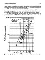
FIGURE 6. Erosion as a function of impact
angle. (From Eyre, T. S., Tribol. Int., 11(2),
91, 1978. With permission.)
Erosion
Erosive wear can be caused by either solid participates or liquid droplets striking the
surface at high velocities.
16,17
In this chapter, emphasis is placed on erosive wear by solid
particle impact. Typical problem areas include: compressor and turbine blading, helicopter
rotor blades, impeller-type pumps, pressure letdown valves, etc.
Since the contact stress results from kinetic energy of the particles in the fluid stream,
size and density of the particles, their velocity, and angle of impact must all be considered.
Erosive weight loss is roughly proportional to the square or cube of velocity. Relative
hardness and shape of the particle, its fracture characteristics, and the ductility of the solid
surface also influence the resulting damage.
As illustrated in Figure 5, cutting wear predominates at low angles of impingement for
ductile metals unless the particles are smooth spheres. The harder the surface, the lower the
rate of material removal. At higher angles of impact, hard, brittle materials show more
erosive wear as elastic properties of the surface become much more important. Annealed
materials often erode less than the same alloy in the hardened state. An elastomeric coating
may be a very viable solution to erosion at high angles of impingement. Figure 6 compares
the relative effect of impact angle on wear rates for a metal and a rubber material.
While surface hardness becomes relatively less significant at high angles of impact,
coatings of very hard materials are being used to prevent erosion damage at both high and
low angles of impact. For example, Hansen et al.
18
evaluated a large variety of metals,
alloys, carbides, and ceramics in a sandblast type of test at 20 and 700°C with 90 and 20°
angles of impingement. As shown in Table 3, some ceramics and carbides with a low metal
binder content were more erosion resistant than metals or alloys. Hard coatings that were
particularly effective included: chemical vapor-deposited SiC, electrodeposited TiB
2
, bonded
Mo, and bonded WC cermets. Generally, coating thicknesses of about 50 to 80 µm (0.002
to 0.003 in.
2
) were necessary for adequate protection. These test results have been partially
verified by evaluation of control valve components in coal gasification plants.
The above results are of fundamental interest for the following reasons:
1.Contrary to other basic studies (e.g., the results illustrated in Figure 5), some hard,
brittle materials can be very effective at high-impingement angles.
2. Most metals and alloys, except molybdenum, have essentially the same erosion rates.
3. Thin, hard coatings can provide erosion protection for softer metal substrates.
630 CRC Handbook of Lubrication
Copyright © 1983 CRC Press LLC
Generally, rougher or more porous surfaces are less prone to lubricant depletion. The
valleys or pores also serve as reservoir traps for loose debris. However, rough surfaces are
also more susceptible to fatigue-type wear. Sprayed metal coatings such as molybdenum or
copper have been used successfully in certain applications. These coatings tend to be porous
because of oxidation of the metal during the spraying operation. Another coating system
which should be promising is bonded molybdenum with its surface hardness of about 3000
Knoop. The coating could be applied by spraying molybdenum on the substrate, grinding
the surface smooth, and then bonding to produce a hard, porous surface. Other processes
which can produce hard porous surfaces include spark hardening, selective etching, and
porous chrome plating.
Chemical Wear
Exposure of fresh metal surfaces, coupled with the high pressures and flash temperatures
developed at contacting asperities, create ideal conditions for chemical reactions in sliding
contacts. These reaction films serve to prevent bare metal-to-metal contacts and welding or
metal transfer. However, under certain conditions, an excessive amount of soft reaction
product is produced which then wears away rapidly.
This corrosive wear could be attributed to a number of factors. These include:
1. Excessively high-operating temperature. This promotes lubricant oxidation to form
acidic and corrosive products and also increases reaction rates.
2. Use of reactive chemical additives (EP agents). Additives containing phosphorous,
sulfur, or chlorine are often used in lubricants to form protective inorganic films on
heavily loaded bearing surfaces. Such compounds corrode certain bearing alloys, and
also become overly reactive at high temperatures.
3. Excessive moisture in the lubricant. This problem is particularly acute in marine
applications. Tin-base babbitt forms a relatively hard “scab” with seawater contam-
ination that can abrade a steel journal. Pitting corrosion because of water contamination
is a major cause of ball bearing failures on naval aircraft.
19
4. Atmospheric corrosion. Many industrial components operate, unlubricated, in exposed
locations. Rust formation of ferrous alloys and subsequent abrasion results in rapid
material loss.
Changes in bearing alloy composition, electroplating, diffusion treatments, chemical con-
version coatings, and organic coatings are all potential solutions to the problem. Research
is also being directed toward new techniques such as ion implantation to change the char-
acteristics of metal surfaces.
Cavitation-Erosion
Cavitation involves gas- or vapor-filled bubbles or pockets in flowing liquids as a result
of the dynamic generation of low pressure. Collapse of these bubbles can generate extremely
high pressures and velocities in the fluid. Adjacent solid surfaces may be rapidly pitted and
eroded by this action. This type of wear is particularly serious in valves, impeller-type
pumps, and propellers. Hobbs
20
correlated cavitation-erosion with ultimate resilience, ex-
pressed as follows:
Plastics and elastomers with high-tensile strength and resilience have been used success-
632 CRC Handbook of Lubrication
Copyright © 1983 CRC Press LLC
fully as protective coatings on metal substrates. Strong adhesion of the coating is essential.
Metal overlays or inlays are effective in certain applications when flame- or plasma-sprayed,
welded, or electroplated. In general, cavitation damage decreases with increasing hardness,
particularly among materials of the same general class.
SUBSTRATE AND COATING CONSIDERATIONS
This section considers the various types of surface treatments shown in Table 1 and the
processing variables involved.
Coatings Applied on the Surface
Electroplating
This process is applicable to practically any metal surface and, by suitable preparation,
to plastics and many other nonconducting materials. Since it is a low-temperature process
(<100°C), warpage or dimensional changes are avoided.
There are disadvantages. Hydrogen embrittlement can occur with certain alloys. Quality
control and adhesion may be problems. Since electroplating is a line-of-sight process, holes,
recesses, and complex shapes should be avoided.
Despite these problems, a variety of platings are used as wear-resistant coatings. These
range from soft, conformable coatings such as tin- or lead-base alloys, to hard chrome.
Thicknesses normally range from 2.54 (0.0001 in.) to 500 µm (0.020 in.), although platings
as thick as 3180 µm (0.125 in.) are possible with some metals. Electroplated precious metals
such as gold, silver, and rhodium are used for sliding electrical contacts as well as specialized
bearing applications. For selective plating of worn surfaces in the field, a porous electrode
impregnated with proprietary plating solutions can be used to brush-plate limited areas.
21
This technique is used to repair scratches or flaws in chrome-plated cylinders and to build
up worn areas on babbitted bearings.
Electroplating can increase surface hardness, improve corrosion resistance, provide soft
and conformable coatings, or create a nonsoluble material combination with lower adhesion.
Electroless Deposition
Certain metals, such as nickel, copper, and cobalt can be deposited by chemical reduction
from aqueous solutions at temperatures below 100°C. Electroless nickel is most widely used.
Although more expensive than electroplating, electroless deposits are uniform and protective,
and complex shapes including holes and ID surfaces can be coated. Most metals, except
lead, cadmium, tin, and bismuth can be plated. The deposition rate is slow; thicknesses
range from 2.54 (0.0001 in.) to 180 µm (0.007 in.).
Electroless nickel plate contains about 8 to 10% phosphorous. As deposited, the hardness
is about 500 Vpn (49 Rc), but can be increased to about 1000 Vpn (70 Rc) by heat treating
the plated part at 400°C. Despite its hardness, practical experience with electroless nickel
as a wear-resistant coating has often been disappointing. Lubrication is essential; electroless
nickel is not recommended for dry sliding applications. Silver plating the opposing surface
is reported to be beneficial. When considering electroless nickel for a bearing surface,
evaluations should be made under conditions simulating the actual application.
Composite platings of very fine hard particles dispersed in an electroless nickel matrix
appear to be much more effective than straight electroless nickel for wear resistance. The
particles are suspended in the plating bath and codeposit with the nickel, Silicon carbide is
widely used for the hard particles, but diamond is also commercially available. Particle size
and shape are critical and the surfaces must be finished so that no sharp peaks project from
the surface. These platings are used extensively for molds which must resist abrasion from
glass fiber-reinforced plastic parts
22
and also for guides and rollers subjected to abrasion by
textile fibers.
Volume II 633
Copyright © 1983 CRC Press LLC
Vapor Deposited Coatings
Although the principles of vapor deposition have been known for over 80 years, industrial
applications have been very limited. Two application techniques are being used: chemical
vapor deposition (CVD) and physical vapor deposition (PVD).
23
In CVD, the coating is
formed either from gaseous chemical reactants at the substrate surface, or by thermal de-
composition of volatile compounds such as the carbonyls. In PVD, the coating is evaporated
or sputtered from the source to the substrate. Recent interest centers around the use of thin,
hard coatings on cutting tools. In CVD of titanium carbide on cemented tungsten carbide
tool bits, as an example, titanium tetrachloride is vaporized, mixed with hydrogen and
methane, and fed into a reaction chamber containing the tool bits. These parts are heated
to 800 to 1000°C and the following reaction takes place at the surfaces;
Strong bonding takes place because of some diffusion. Tool life is reportedly improved by
factors of 4 to 10. Certain carbides, nitrides, borides, and oxides of metals such as titanium,
silicon, tungsten, and chromium can be deposited.
CVD is also used commercially to apply hard, wear-resistant coatings of silicon carbide
on carbon-graphite seal faces. Test results have shown that this material runs best against
itself in displaying outstanding resistance to wear by abrasives in the fluids.
24
This process has limitations. It is most economical when a large number of parts are
treated simultaneously, but part size is limited by the size of the reaction chamber. Process
temperatures are so high that many substrate alloys would be annealed. Reduction of the
process temperature will retard diffusion and reduce adherence of the coating. Vapor dep-
osition should be useful for creating hard surfaces on small parts made from stainless steels
and nickel- or cobalt-base superalloys.
The lower processing temperature with PVD permits coating of high-speed steel tools
without excessively softening the substrate. Adherent coatings have been obtained at tem-
peratures below 500°C.
Sprayed Coatings
Any material that can be melted without decomposition can be sprayed as a surface
coating.
25
Plasma or detonation gun coatings of ceramics, carbides, and refractory metals
(Mo and W) are of particular value for upgrading wear resistance. A major disadvantage is
that this is a line-of-sight process. The densest and most adherent coatings are those sprayed
perpendicular to the surface. As the impact angle decreases, coating quality drops and
spraying angles below 45° are definitely not recommended. The amount of heat that must
be dissipated limits the ability of even specialized “mini-gun” equipment to coat bores less
than about 75 mm (3 in.) in diameter and longer than 100 mm (4 in.). Flat surfaces and
outside diameters are no problem.
Practically any metallic substrate can be spray coated. Size is no impediment. With
reasonable care, bulk temperature of the substrate can be kept below 175°C (350°F). While
steel grit blasting is normal practice, steel particles embedded in the substrate can rust and
cause blisters in the coating. In critical applications, grit blasting with sharp, fresh Al
2
O
3
abrasive avoids this problem. All coating should be done as soon as possible after abrasive
blasting. Since it is difficult to roughen hard metal surfaces such as hardened steel by
abrasive blasting, a thin-sprayed undercoat of metal such as nickel-chrome or nickel alu-
minide should be applied first to provide a rough base for the final coating.
For ceramic and carbide coatings, thicknesses range from about 100 (0.004 in.) to 1000
µm (0.04 in.). Heavier coatings of metals can be deposited, and plasma spraying is widely
used for salvage and repair work. If the coatings are to be finish-ground for bearing or shaft
634 CRC Handbook of Lubrication
Copyright © 1983 CRC Press LLC
surfaces, the as-sprayed coating should be at least twice as thick as the finished coating.
This will ensure minimum porosity and optimum cohesion and adhesion. The finished coating
thickness should be as thin as possible to minimize problems. Coating vendors should be
consulted in selecting sliding combinations. Mating a sprayed oxide coating against a metal
is particularly risky since the metal tends to transfer to the ceramic as islands of work-
hardened material which can then severely abrade the opposing metal surface. Such com-
binations should be carefully evaluated before specifying them for practical applications.
Where substrate corrosion is a problem, corrosion-resistant metal undercoatings, e.g.,
nickel aluminide, can help Soft nickel plate has also been used, but must be grit blasted
before the final coating is applied. Care is needed to avoid exposing the substrate.
Other variations of these coatings involve spraying and fusing. The fusing step requires
very high temperatures which could affect the metallurgy of the substrate.
Sputtering
In this process, atoms of material from a negatively charged target of the coating material
are vaporized by bombardment with positive ions of an inert gas such as argon. These atoms
are then transported, in the vapor phase, through the plasma of ionized gas and deposited
on the surface to be coated.
26,27
Coatings of metals, alloys, solid lubricants, and hard materials
such as oxides and carbides can be applied. Substrate heating is negligible. These coatings
are characteristically uniform and very thin, ranging in thickness from 50 (500 Å) to 1000
nm (10,000 Å). The process is ideal for applying wear-resistant coatings on precision
components such as gas bearings or rolling contact bearings because no subsequent finishing
is required.
Reverse sputtering before coating removes any contamination from the surface and enables
outstanding adherence. Even very hard coatings such as TiB
2
or Cr
2
O
3
can be flexed,
brinelled, or bent over a small radius without cracking. Wear life of a sputtered coating
appears to compare favorably with similar coatings 1000 times thicker deposited by other
processes.
Although the process requires a vacuum, it can be automated to some extent. Graded
coatings can be applied, without breaking vacuum, if the equipment has provision for multiple
targets.
In ion implantation, the evaporated material is ionized and accelerated to the workpiece
by electrical fields. The ions actually penetrate the surface. Both wear and corrosion resistance
can be affected.
28
Hard Facings
By welding, or spraying and subsequent fusion, various wear-resistant alloys can be
deposited on metal substrates.
29,30
This technique is widely used for heavy-duty industrial
and construction equipment which is subject to severe wear by abrasion or impact-abrasion.
Hard facings are used on new equipment and also find wide application in building up
and salvaging worn parts. The process has many advantages: wide ranges of coating materials
are available, heavy deposits are feasible, repairs can be made in the field, metallurgical
bonding is obtained, some coatings are corrosion resistant, and expensive materials are
conserved by applying the coatings on low-cost substrates. For abrasion resistance, hard
materials, e.g., metal-bonded tungsten carbide, cobalt alloys, and nickel-chrome-boron are
used. For maximum impact resistance, high manganese work-hardening steels perform best.
Chrome steels and low alloy or carbon steels are in many cases comparable or better in
abrasion resistance than the more expensive cobalt-base alloys.
Aside from processing temperature and cost, the major drawback to hard facings is the
possibility of cracking in some applications, particularly with thick deposits. The very high-
surface temperatures involved may also affect the substrate.
Volume II 635
Copyright © 1983 CRC Press LLC
Organic Coatings
Many plastic and elastomeric coatings have been used as wear-resistant surfaces on metal
substrates. Typical examples include:
Teflon
®
Acrylics
Nylon Polyurethanes (rigid)
Vinyls Polyamide - imides
Epoxies Polyphenylene sulfide
Phenolics Aromatic polyesters
In many cases, these plastics also provide corrosion protection.
By compounding powdered solid lubricants, such as MoS
2
, graphite, or Teflon into a
suitable resin matrix, a variety of wear-resistant solid lubricant films with outstanding fric-
tional characteristics have been obtained. These coatings are covered in the chapter on
Lubricant Types and Their Properties (Volume II).
Elastomeric coatings effectively prevent erosive or abrasive wear under certain conditions.
As long as the velocity of an eroding particle is not too high, the elastomer surface deforms
and recovers elastically with no damage. In abrasive-blasting booths, durable rubber gloves
protect the operator’s hands. Hard, tough polyurethane elastomers are used to coat steel tires
on industrial equipment such as forklifts and carts which operate on rough, hard surfaces.
Some new abrasion-resistant plastic coatings have provided unique durability on the hulls
of icebreakers.
31
A large number of candidates were screened and a nonsolvented poly-
urethane and a nonsolvented epoxy were selected for trials. After four years of service, both
coatings have remained essentially intact. Similar coatings have shown promise for pre-
venting cavitation damage on ship propellers.
These plastic-and elastomeric coatings can be applied by spraying, brushing, dipping,
and fluidized bed. Surface preparation is a major consideration and abrasive grit blasting
has been found to be very suitable. Durable coatings usually require heat curing at temper-
atures up to 175°C (350°F), although some newer materials require temperatures as high as
350°C (660°F). This can be a problem with certain substrate materials, especially age-
hardened aluminum alloys.
Chemical Conversion Coatings
Various processes are used to form in situ inorganic coatings on metals.
1,32,33
Unlike
bonded solid lubricant films, these conversion coatings do not necessarily provide low friction
or long life. Their primary function is to prevent bare metal-to-metal contacts and promote
surface smoothing during the early stages of run-in when surface imperfections can penetrate
through the lubricant film. The most common types are phosphates, sulfides, and oxides.
Phosphating to produce a complex inorganic phosphate surface is the most widely used
process. For application, parts are immersed in aqueous solutions of phosphates at a tem-
perature of about 93°C (200°F).
32
A manganese phosphate coating is generally best for wear
resistance because it is relatively soft and tends to “smear” over the contact area. Zinc
phosphate produces a harder coating and is used primarily as a substrate pretreatment for
improving the adherence of protective polymer coatings. Coating thicknesses range from
2.54 to 38 µm (0.0001 to 0.0015 in.), depending on the application temperature and bath
composition. Such coatings can be applied to cast iron, steel, zinc, and cadmium, but not
to stainless or other corrosion-resistant alloys. As a rule of thumb, 50% of the coating
thickness penetrates the surface and 50% appears as dimensional growth. The coatings are
porous (more so in thicker layers) and this helps to retain the lubricant. Phosphating is
particularly useful for applications such as gears or piston rings where initial conformity
may not be ideal. Besides their beneficial effects on sliding, these coatings also provide
corrosion protection.
636 CRC Handbook of Lubrication
Copyright © 1983 CRC Press LLC
Sulfide coatings are generally applied from molten salt baths at temperatures ranging from
190°C to about 550°C.
1,33
Both electrolytic and chemical processes are used. Coatings are
characteristically Jess than 10-µm (0.0004-in.) thick. Because the salt baths contain cyanides
or cyanates, the coating actually consists of iron nitrides as well as sulfides. Unlike the
phosphates which are easily friable, sulfide coatings are very wear resistant. They can be
applied to a wide variety of ferrous alloys, even low-carbon steels which normally would
not respond well to nitriding.
Oxide films of significant thickness can also be produced on metal surfaces.
1,33
Anodizing
aluminum to produce a hard A1
2
O
3
surface is widely used to improve wear resistance.
Magnesium, titanium, and beryllium can also be anodized. These anodized coatings are
hard and brittle surface layers, supported on relatively soft substrates; brinnelling loads can
crack the coatings, resulting in high wear. A similar result would be obtained if a hard
particle were trapped between two anodized surfaces.
Since anodizing is done at temperatures below 100°C, metallurgical changes are no prob-
lem. Films as thick as 100 µm (0.004 in.) are used. By first creating a porous, hard-anodized
coating and then impregnating it with Teflon
®
or other solid lubricant, improved sliding
performance can be obtained. These anodized films have a relatively short wear life in dry
sliding; however, a thin wiped film of oil or grease increases the life dramatically.
Ferrous alloys can be oxidized by various processes.
1,33
Proprietary salt baths of caustic/
nitrate solutions or molten nitrate/nitrite baths are often used. Heating steel in steam at 260
to 400°C can also produce an adherent oxide coating. The latter process, part of the “Ferrox”
treatment, is often used for treating piston rings. Like the phosphate treatments, these oxide
coatings minimize bare metal contacts and prevent scuffing in lubricated applications such
as gears, needle bearings, and piston rings.
Thermal Treatments
Steels and cast irons which contain enough carbon to be through-hardened in thin sections
can be case hardened by localized surface heating to produce a hard, wear-resistant martensitic
structure with a tough, ductile core. Two production techniques are being widely used:
induction heating and flame hardening.
34
In addition, electron beam and laser hardening are
becoming more commonplace.
35,36
Flame hardening does not lend itself to close control,
but it is particularly suitable for large parts. The other three processes can be closely controlled
by varying the energy input. Advantages of these thermal treatments are reduced energy
consumption, ability to selectively harden surfaces which require wear resistance, high
production rates, and ease of automation. Gears, cams, and shafts are among the many
machinery components that can be surface hardened by these methods.
Chill casting is also used to harden critical surfaces on cast iron parts which contain about
3% carbon. Instead of allowing slow cooling with formation of graphite flakes, chills are
used to cool the cast iron rapidly and cementite (Fe
3
C) is formed.
37
Other carbide-forming
elements such as chromium and vanadium are also added to promote surface hardness. Cast
cam shafts and cam followers can be hardened by this method.
Diffusion Treatments
A variety of commercial diffusion treatments increase the wear resistance of metals,
particularly steel and iron parts. Case carburizing and nitriding are the most prominent, and
many modifications are available to achieve specific changes in surface chemistry and
metallurgical structure. Extensive information is available in the literature
1,37,38
and from
suppliers. In many cases, the difference in chemistry has significant effects on lubrication
and sliding behavior.
Diffusion treatments uniquely permit selection of a steel with optimum core strength.
Wear resistance is then provided by the surface diffusion process. Gears, splines and many
Volume II 637
Copyright © 1983 CRC Press LLC
other components subject to bending stresses particularly benefit from this approach. As an
added bonus, case carburizing or nitriding improves the fatigue properties of steels, Nitriding
carbon or low alloy steels also upgrades their corrosion resistance, but lowers that of stainless
steel.
Most carburizing and carbonitriding processes are done above the transformation tem-
perature of the steels. Quenching or subsequent heat treatment to achieve desired properties
may induce dimensional changes or warpage. Since nitriding is done below the transformation
temperature, dimensional changes are minimized. In many cases, no subsequent finishing
is required.
Proprietary molten salt bath processes are used to apply very thin (10 to 100 µm), relatively
soft nitride coatings on steel. These are often times very effective. Application temperatures
are about 570°C (1050°F).
Table 4 compares some commercial diffusion processes. Practical limits on case depths
are established by diffusion rates of the elements. The heavier the case, the higher the cost
and the greater the dimensional changes. Case depth wear resistance is generally ranked as
follows:
If brinelling results because of indentation-type loading, either the case depth must be
increased or the substrate strength upgraded.
Other diffusion processes have been developed to upgrade wear resistance of both ferrous
and nonferrous alloys. Siliconizing
39
and bonding
40
are examples.
Miscellaneous Treatments
This category includes cold-working, spark-hardening, sintered porous surface coatings
impregnated with solid lubricants, and laser alloying. A variety of mechanical reduction and
burnishing processes can also upgrade surface hardness to some extent, as well as provide
improved surface texture and fatigue resistance.
Spark hardening is used routinely to apply thin, wear-resistant coatings such as tungsten
carbide on tools, chucks, dies, etc. A positively charged electrode of the coating material
is vibrated against a negatively charged substrate. Each time contact is made, current dis-
charges from a condenser and material is deposited on the surface. The resulting surface is
normally rough, but proprietary processes are available for better finishes. Wolfe
41
found
that sparked silver coatings were particularly promising, possibly because the pores acted
as lubricant reservoirs. This suggests that a sparked layer of silver might inhibit fretting
wear.
Impregnating a porous surface layer with a solid lubricant has been the subject of a number
of investigations. Best known material is probably the DU supplied by Glacier Metals, Ltd.
Spherical bronze particles are sintered on a steel or bronze backing and the porous layer is
then impregnated with Teflon
®
and lead. The material is produced as flat-strip stock which
can then be machined, punched, or rolled to form washers, sleeve bearing inserts, etc.
In laser alloying, the laser creates a thin, molten layer on the metal surface. Alloying
elements are then introduced into the molten skin. This technique can form a coating whose
chemistry and corrosion or wear resistance is markedly different than the substrate.
36
638 CRC Handbook of Lubrication
Copyright © 1983 CRC Press LLC
640CRC Handbook of Lubrication
Table 5
SOME PRACTICALAPPLICATIONS FOR WEAR-RESISTANTCOATINGS
TYPICALAPPLICATIONS FOR WEAR-RESISTANTCOATINGS
Most surface treatments listed in Table 1 are particularly applicable to ferrous alloys.
Ultimate choice depends on factors such as: cost, effect of process temperature on the
substrate, and the dominant modes of wear. Hard, diffusion coatings are particularly valuable
for gears, cams, crankshafts, etc., where through hardening would result in a brittle material.
Stainless steels can be hardened to thin-case depths by nitriding or bonding. For thicker
coatings, spraying or hard facing would be best.
Aluminum, titanium, and magnesium alloys can be anodized to improve wear resistance.
However, where concentrated loading is encountered, substrate deformation and subsequent
cracking of the coating is likely. Diffusion treatments for these metals and alloys are limited
to a few proprietary processes which involve electroplating followed by thermal diffusion.
33
With the exceptions of chemical vapor deposition and hard facing, all processes listed in
Table 1 for applying coatings on the surface (e.g., spraying, plating, sputtering, etc.) can
be used with these alloys. Thin layers of tin alloys are often used to upgrade the performance
of aluminum bearings.
Plasma-sprayed oxide coatings are particularly effective for hard surfacing aluminum and
titanium alloys as long as solid particle erosion or impact loading is not a problem. Metal-
bonded carbides would be more suitable for erosion resistance. Mismatches in thermal
expansion coefficients, as on aluminum, are rarely a problem as long as the coatings are
reasonably thin, on the order of 50 to 150 µm (0.002 to 0.006 in.). Like anodizing, the
real problem is substrate deformation under load.
When coatings are required on copper alloys, electroplating or spraying techniques are
applicable.
Superalloys are frequently plasma-sprayed with ceramics or carbides for improved wear
resistance. Aluminum oxide or nickel-chrome bonded chrome carbide are very effective at
high temperatures (to 1000°C). Bonding also produces very hard surface coatings.
Table 5 categorizes coating processes used to resolve wear problems. One obvious con-
Copyright © 1983 CRC Press LLC
Volume II 641
Table 6
SUMMARY OF APPROACHES TO SELECTION OF WEAK-RESISTANT COATINGS
Copyright © 1983 CRC Press LLC
642 CRC Handbook of Lubrication
Table 6 (continued)
SUMMARY OF APPROACHES TO SELECTION OF WEAR-RESISTANT COATINGS
a
Some very hard coatings are promising for high-angle impact.
Copyright © 1983 CRC Press LLC
elusion: in many applications two types of coatings with entirely different physical properties
might provide equally satisfactory service. For example, a hard brittle coating or an elastomer
coating might both be suitable for reducing erosive wear. Table 6 presents typical examples
of coatings for resolving specific wear problems.
Currently, emphasis is being placed on variations in conventional coating techniques,
such as ion nitriding, laser hardening and laser glazing or surface alloying. These offer
advantages, such as better process control, shorter process times, and the ability to selectively
harden surfaces. Future trends appear to be directed toward surface modifications by ion
implantation, chemical vapor deposition, and selective diffusion of elements from fused salt
baths.
REFERENCES
1. Wilson, R. W., Surface treatments to combat wear, First European Tribology Congress, C278/73, Spon-
sored by the Tribology Group, Institute of Mechanical Engineers, Mechanical Engineering Publications,
London, September 1973, 165.
2. Special feature issue, Wear resistant surfaces, Tribol. Int., Vol. 11(2), 91, 1978.
3. Czichos, H., Tribology: A Systems Approach to the Science and Technology of Friction, Lubrication and
Wear, Elsevier, New York, 1978.
4. Eyre, T. S., Wear characteristics of metals, Tribol, Int., 9, 203, 1976.
5. Finken, E. F., Abrasive wear, Evaluation of Wear Testing, ASTM STP 446, American Society for Testing
and Materials, Philadelphia, 1969, 55.
6. Tallian, T. E., Elastohydrodynamic Hertzian contacts. II, Mech. Eng., 17, December 1971.
7. Eyre, T. S., The mechanisms of wear, Tribol. Int., 11(2), 91, 1978.
8. Krushchov, M. M, and Babichev, M. A., The effeel of heat treatment and work hardening on the resistance
to abrasive wear of some alloy steels, in Friction and Wear in Machinery, Vol. 19, American Society of
Mechanical Engineers, New York, 1964, 1.
9. Diesburg, D. E. and Borik, F., Optimizing abrasion resistance and toughness in steels and irons for the
mining industry, in Source Book on Wear Control Technology, Rigny, D. A. and Glaeser, W. A., Eds.,
American Society for Metals, Metals Park, Ohio, 1978, 94.
10. Avery, H. S., Austenitic manganese steel, in Metals Handbook, Vol. 1, 8th ed., American Society for
Metals, Metals Park, Ohio, 1964, 834.
11. Richardson, R. C., Wear of metals by relatively soft abrasives, Wear, 11, 245, 1968.
12. Tabor, D., Moh’s hardness scale — a physical interpretation, Proc. Phys. Soc. (London), 67(3-B), 249,
1957.
13 Archard, J. J. and Hirst, W., The wear of metals under unlubricated conditions, Proc. R. Soc. (London),
A236, 397, 1956.
14. Buckley, D. H. and Johnson, R. L., The influence of crystal structure and some properties of hexagonal
metals on friction and adhesion, Wear, 11, 405, 1968.
15. Peterson, M. B., Lee, R. E., and Florek, J. J., Sliding characteristics of metals at high temperatures,
ASLE Trans., 3(1), 101, 1960.
16. Preece, C., Erosion, Academic Press, New York, 1979.
17. Finnie, I., Some observations on the erosion of ductile metals, Wear, 19, 81, 1971.
18. Hansen, J. S., Kelly, J. E., and Wood, F. W., Erosion Testing of Potential Valve Materials for Coal
Gasification Systems, Bureau Mines Rep. of Investigation No. 8335, 1979, 26.
19. Cunningham, J. S. and Morgan, M. A., Review of aircraft bearing rejection criteria and causes, Lubr.
Eng.,
35(8), 435. 1979.
20. Hobbs, J. M., Experience with a 20-KC cavitation erosion test, in Erosion by Cavitation or Impingement,
ASTM STP 408, American Society for Testing Materials, Philadelphia, 1967, 159.
21. Rubenstein, M., Fluid power in aerospace, Hydraul. Pneumatics, 25(9), 202, 1973.
22. Anon., Mold corrosion, abrasion checked with new silicon-carbide coating, Mod. Plastics, 66 and 68, July
1976.
23. Archer, N. J., “Vapor deposition of wear-resistant surfaces,” Tribol. Int., 11(2), 135, 1978.
24. Panel Discussion, High performance seal materials, Lubr. Eng., 35(6), 309, 1979.
Volume II 643
Copyright © 1983 CRC Press LLC
25. Committee Rep., Thermal spraying, in Welding Handbook, 6th ed., Phillips, A. L., Ed., American Welding
Society, New York, 1969, chap. 29.
26. Stupp, B. C., Sputtering and ion plating as industrial processes, preprint No. SAE 730547, presented at
the SAE Automobile Eng. Meet., Detroit, May 1973.
27. Spalvins, T., Microstructural and wear properties of sputtered carbides and silicides, in Source Book on
Wear Control Technology, Rigny, D. A. and Glaeser, W. A., Eds., American Society for Metals, Metals
Park, Ohio, 1978, 348.
28. Dearnaley, G., Ion implantation of engineering components, in Advances in Surface Coaling Technology,
Welding Institute, Abington Hall, Cambridge, 1978, 111.
29. ASM Committee, The selection of hard facing alloys, in Metals Handbook, Vol. I, 8th ed., American
Society for Metals, Metals Park, Ohio, 1964, 820.
30. Committee Rep., Surfacing, in Welding Handbook, 6th ed., Walter, S. T., Ed., American Welding Society,
New York, 1969, chap. 44.
31. Calabrese, S. J., Buxton, R., and Marsh, G., Frictional characteristics of materials sliding against ice,
Lubr.Eng., 36(5), 283, 1980.
32. ASM Committee, Phosphate coating, in Metals Handbook, Vol. 2, 8th ed., American Society for Metals,
Metals Park, Ohio, 1964, 531.
33. Gregory, J. C., Chemical conversion coatings of metals to resist scuffing and wear, Tribol. Int., 11(2),
105, 1978.
34. ASM Committee, Induction hardening and tempering, Flame hardening, in Metals Handbook, Vol. 2, 8th
ed., American Society for Metals, Metals Park, Ohio, 1964, 167.
35. Jenkins, J. E., Electron beam surface hardening, ToolProd., 44(9), 76, 1978.
36. Desforges, C. D., Laser heat treatment, Tribol. Int., 11(2), 139, 1978.
37. Elliot, T. L., Surface hardening, Tribol. Int., 11(2), 121, 1978.
38. ASM Committee Case hardening of steel, in Metals Handbook, Vol. 2, 8th ed., American Society for
Metals, Metals Park, Ohio, 1964, 93.
39. Kanter, J. J., Siliconizing of steel, in Metals Handbook, 8th ed., Vol. 2, American Society for Metals,
Metals Park, Ohio, 1964, 529.
40. Fiedler, H. C. and Sieraski, R. J., Boriding steels for wear resistances, in Source Book on Wear Control
Technology, Rigny, D. A. and Glaeser, W. A., Eds., American Society for Metals, Metals Park, Ohio,
1978, 364.
41. Wolfe, G. F., Effect of surface coatings on the load-carrying capacity of steel, Lubr. Eng., 19, 28, 1963.
42. Tilly, G. P.,
Sand erosion of metals and plastics, Wear, 14, 241, 1969.
644 CRC Handbook of Lubrication
Copyright © 1983 CRC Press LLC
SYSTEMS ANALYSIS
Horst Czichos
INTRODUCTION
The foregoing chapters of the handbook have amply illustrated that there is a great range
of technical systems to be lubricated as well as a great variety of tribological processes,
i.e., contact, friction, lubrication, and wear processes, that occur in lubricated systems.
Whereas complex problems of this type have been solved in the past by isolating single
events and treating these in terms of simplified cause-effect relationships, today a “multi-
disciplinary” or “systems” approach is needed.
1,2
The purpose of this chapter is to present an overall systems view which may help to
systematize approaches to the solution of lubrication problems, taking into account the various
influencing factors, processes, and parameters. For more details the reader is referred to
Reference 3, and References 4 to 7 provide examples of the general development and
application of systems theory in contemporary science and technology.
THE SYSTEM CONCEPTAND ITS APPLICATION TO TRIBOLOGY
General Considerations
As a starting point for an engineering systems approach to the analysis of tribological
systems, consider a typical lubricated mechanical system, namely a gearbox. The technical
purpose of this system is to transform certain “inputs”, i.e., torque and angular velocity,
into “outputs”. The transformation occurs through the contact of gears, and as a consequence
of interactions of the gear teeth, friction and wear processes occur.
Lubrication represents a deliberate attempt to avoid or reduce the effect of friction and
wear upon a mechanical system. Alubricant can also act, as it flows away, as a cooling
agent removing heat from the location of the friction process. If the sliding or rolling surfaces
are completely separated by the action of a lubricant at all times, there may be no wear
process. In this event, the analysis is simplified (“no-wear model”). However, if in a
lubricated slate there is some contact between surfaces or between boundary lubricants on
the surfaces, the interfacial tribological processes are of paramount concern. In such cases,
the presence of a lubricant may complicate the analysis, partly because the reaction products
present may be complex and difficult to characterize, and partly because transient conditions
may be the major concern.
The first step in a systems analysis is proper identification and isolation of the problem.
As shown in Figure 1 for the example of a gearbox, the two partners (or the two “systems
elements”) which form the tribologically interacting surfaces, i.e., gear 1 and gear 2, can
be hypothetically separated from their environment by the proper choice of a “system
envelope”. All components of the system are then by definition within this envelope and
are part of the so-called internal “structure” of the system. The structure consists of the
elements (A) of the system, their relevant properties (P), and their interrelations (R), described
formally by the set S = {A, P, R}.
The “external” quantities which cross this system envelope from the outer world are the
“inputs” of operating variables, and the quantities which cross the system envelope from
the inside are the “outputs”. In other words, the inputs of the operating variables are
transformed through the structure of the system into outputs which are used, the use-outputs.
Simultaneously, as a consequence of interactions between the elements, loss-outputs occur,
denoted in summary by the terms friction and wear losses. The way in which the inputs are
transformed into outputs determines the technical function of the system.
Volume II 645
Copyright © 1983 CRC Press LLC
FIGURE 2. Types of tribological systems.
Table 1
CLASSIFICATION OF TECHNICAL FUNCTIONS OF
TRIBOLOGICAL SYSTEMS
Volume II 647
Copyright © 1983 CRC Press LLC
information by utilizing the motion of macroscopic bodies are steadily being replaced by
devices in which there is little or no mechanical motion, for example the replacement of
the mechanical clock by digital electronic clocks. In other instances materials are not merely
moved but also changed in state or form.
In applying the system concept to other technical systems, e.g., electrical or electronic
systems, the functional behavior of the system is often described in terms of mathematical
input-output relations. However, in attempting to apply the system concept to the subject
of tribology, a fundamental difference must be emphasized between the behavior and the
functional description of electrical systems and mechanical systems in which friction and
wear processes occur.
Compare, for example, the behavior of an electrical transformer and a mechanical gearbox.
At a first glance, the functional purpose of both systems appears to be analogous, i.e., to
transform certain inputs — voltage and current in the electrical system, and angular velocity
and torque in the mechanical system, respectively — into outputs used for technical purposes.
The function of both systems may be described formally as a transformation of the inputs
into the outputs via a certain transfer function. However, the dynamic performance of both
systems is accompanied by perturbations. In both systems, energy losses occur due to
electromagnetic or frictional resistances. The fundamental difference between the behavior
of the electrical and mechanical systems originates from their different “structure”. The
structure of the electrical system generally remains constant with time. In this case, the
transfer function can be worked out mathematically. This has led to various applications of
(he powerful systems engineering method of network theory and related methods charac-
terizing functional behavior.
8-10
In the mechanical case, however, the structure of the system
generally changes with time, through friction and wear. This aspect, which is of great
importance for the reliability of the system under question, is described in more detail later.
Operating Variables
The most characteristic operating variable of a tribological system is the type of relative
motion between tribo-element (1) and tribo-element (2). The basic types of motion are
sliding, rolling, spin, and impact. Every type of relative motion between system components
can be expressed as a superposition of these four basic types of motion. In addition to
characterization of the type of motion, its dependence on time should be specified, being
for example: continuous, oscillating, reciprocating, or intermittent.
The other basic operating variables are the following quantities:
1. Load, F
N
2. Velocity, v
3. Temperature, T
4. Distance of motion, s
5. Operating duration, t
For some tribological systems, these physical operating variables are accompanied by
material inputs, e.g., flow rate of the lubricant. Some disturbing inputs may also be present,
e.g., vibration and radiation. It may also be necessary to specify derived quantities, e.g.,
contact pressures, temperature gradients, etc.
Structure of Tribological Systems
As described above, the structure of a tribological system is given by the system elements
(the material components of the system), their relevant properties, and their interrelations
described formally by the set S = {A, P, R}.
648 CRC Handbook of Lubrication
Copyright © 1983 CRC Press LLC
FIGURE 3.Analysis of the structure of tribological systems.
Elements of the System, A
=
{a
i
}
If the system envelope is located as closely as possible around the “interacting surfaces
in relative motion”, four different basic elements are involved in the friction and wear
processes in most tribological systems. As illustrated in Figure 3 for a simple sliding system,
the pair of interacting surfaces involving moving element (1) and stationary element (2).
The other two basic elements are the lubricant (3) (if any) and the atmosphere (4). These
main elements are linked to others or may be composed of subconstituents. For example,
element (3), the lubricant, may consist of a base oil and additives. In Table 2 elementary
elements or components (1), (2), (3), and (4) are listed as examples from every group of
the basic tribological systems compiled in Table 1.
Properties of the Elements, P
=
{P(a
i
)}
Behavior of any tribological system is influenced by many properties of the basic elements
(1), (2), (3), and (4). Although the great variety of tribo-mechanical systems and tribological
processes makes it difficult to provide a comprehensive general compilation, the following
properties of the elements are of primary concern:
1.Properties of tribo-elements (1) and (2): these can be subdivided into “volume” and
“surface” properties. Volume properties: geometry, chemical composition and me-
tallurgical structure, elastic modulus, hardness, density, thermal conductivity.
Surface properties: surface roughness and surface composition.
2.Properties of the lubricant (3): these may be classified into system-independent and
system-dependent properties.
3.Properties of the environmental atmosphere (4): primarily chemical composition and
the amount and pressure of its components, especially water vapor.
Interactions Between the System Elements, R
=
{R(a
i
,a
j
)}
Tribological interactions between the elements of a mechanical system, i.e., the contact,
friction, lubrication, and wear processes, are of paramount interest. Figure 4 provides sim-
Volume II 649
Copyright © 1983 CRC Press LLC
plifiedschematic diagrams for systems of increasing complexity, i.e., increasing number of
interacting elements.
In an ultrahigh vacuum, the simplest tribological system consists only of interacting
partners (1) and (2). The main interactions are then covered by the terms contact deformation,
surface fatigue, abrasion, and adhesion. In air, these processes are supplemented by inter-
actions with the atmosphere (4). Finally in a lubricated system, direct (contact) interactions
between moving and stationary elements are prevented or influenced through the different
mechanisms of lubrication.
Also, interactions between (4) and (3) with (1) and (2) should be taken into account. For
instance, the diffusion of atmospheric oxygen into the lubricant (4) →(3), followed by
oxidation processes between the lubrication and the moving and stationary partners
(3) →(1), (2), can distinctly influence the mechanisms of mixed and boundary lubrication.
Tribological Characteristics
Characteristics that describe the dynamic changes of a lubricated mechanical system as a
consequence of friction and wear processes may be divided into the following three groups:
tribo-induced changes in the system structure, tribo-induced energy losses, and tribo-induced
material losses.
Depending on the processes within a lubricated mechanical system, the tribo-induced
changes of a system structure (a) may concern:
1. Destruction or creation of elements, e.g., the degradation of a lubricant or, on the
contrary, the creation of “frictional polymers”.
2. Changes in properties of elements, for instance, changes in contact topography and
surface composition.
3. Changes in interrelations between elements, for instance, changes of wear mechanisms
under the action of the operating variables, or changes in the lubrication mode.
Friction-induced energy losses (b) and wear-induced materials losses (c) may be expressed
formally as:
Friction losses = f(operating variables; system structure)
Wear losses = f(operating variables; system structure)
Consequently, friction coefficient, f, and wear rate, w, may be expressed formally as:
f = f(X;S)w = f (X;S)
Although parameter groups X and S are not independent variables since they are connected
with each other through the tribological interrelations R, the above symbolic representation
of friction and wear characteristics can be conveniently used as a starting point for application
of the system methodology. From the above symbolic equations it follows that any systematic
approach to the solution of a lubrication problem in a mechanical system must be based on
the detailed knowledge of both the operating variables and the structure of the system.
Influence of Tribological Processes on Structure, Function, and Reliability of
Mechanical Systems
In the upper part of Figure 5, a typical tribological system, namely a gear box, is shown
schematically. As already described in Figure 1, the technical function of the system is to
transform certain inputs, namely angular velocity and torque, into useful outputs via a certain
transfer function.
Volume II 651
Copyright © 1983 CRC Press LLC
In some cases, the failure rate λ(t) of a component in a system can be estimated from the
point of view of the physical behavior of the material used.
l3
Empirically, and sometimes
theoretically, the following probabilities have been proposed:
Exponential Distribution
λ(t) = constant = C
f(t) = C · exp (–Ct)
R(t) = exp (–Ct)
In this case, the failure rate is constant. It means physically that any failure occurs
accidentally without any accumulation of fatigue-like effects during its service time. Many
kinds of electronic components follow this type of failure. Components in a machine break
down in this mode when the failure is brittle fracture.
Rayleigh Distribution
λ(t) = Ct
f(t) = Ct · exp (–Ct
2
/2)
In this case, the failure rate increases with time. The constant. C, indicates the rate of
deterioration of the component which depends upon the stress level applied to it.
Normal Distribution (Truncated)
f(t) = l/s(2π)
1/2
exp {– 1/2 (t –
μ
/s)
2
}
Many components of machines obey this distribution, especially if the failure occurs due
to wear processes. The failure rate of this distribution cannot be expressed in a simple form.
Weibull Distribution
This is a distribution with two parameters, t
o
, the nominal life, and the constant C. The
distribution is found to represent failure of many kinds of mechanical systems, such as
fatigue in ball bearings.
Gamma Distribution
where Γ(x) is a gamma function. This is also a distribution with two parameters. Theoret-
ically, the importance of this distribution is attributed to the equation being an x-fold
Volume II 653
Copyright © 1983 CRC Press LLC