beginning opengl game programming 2004 phần 3 pdf
Bạn đang xem bản rút gọn của tài liệu. Xem và tải ngay bản đầy đủ của tài liệu tại đây (905.31 KB, 42 trang )
Now that you have a handle on lines, let’s move on to the heart and soul of almost every
3D game in existence: the all-mighty polygon.
Drawing Polygons in 3D
Although you can (and will) do some interesting things with points and lines, there’s no
doubt that polygons give you the most power to create immersive 3D worlds, so that’s
what we’ll spend the rest of the chapter on. Before we get into specific polygon types sup-
ported by OpenGL (that is, triangles, quadrilaterals, and polygons), we need to discuss a
few things that pertain to all polygon types.
You draw all polygons by specifying several points in 3D space. These points specify a
region that is then filled with color. At least, that’s the default behavior. However, as you’d
probably expect by now, the state machine controls the way in which the polygon is
drawn, and you’re free to change the default behavior. To change the way polygons are
drawn, you use
void glPolygonMode(GLenum face, GLenum mode);
As you will learn in the next subsection, OpenGL handles the front and back faces of poly-
gons separately; as a result, when you call
glPolygonMode()
, you need to specify the face to
which the change should be applied. You do this by setting the
face
parameter to
GL_FRONT
for front-facing polygons,
GL_BACK
for back-facing polygons, or
GL_FRONT_AND_BACK
for both.
The
mode
parameter can take on any of the values in Table 3.7.
If, for example, you want to set the front-facing polygons to be drawn filled and the back-
facing ones to be rendered as a wire frame (as lines), you could use the following code:
glPolygonMode(GL_FRONT, GL_FILL);
glPolygonMode(GL_BACK, GL_LINE);
Chapter 3
■
OpenGL States and Primitives52
Table 3.7 Polygon Modes
Value Definition
GL_POINT
Each vertex specified is rendered as a single point, the rendering of which can be controlled
by the point states discussed earlier. This basically produces the same effect as calling
glBegin()
with
GL_POINTS
.
GL_LINE
This will draw the edges of the polygon as a set of lines. Any of the line states discussed
previously will affect how the lines are drawn. This is similar to calling
glBegin()
with
GL_LINE_LOOP
.
GL_FILL
This is the default state, which renders the polygon with the interior filled. This is the only
state in which polygon stipple and polygon smoothing (see the following) will take effect.
03 BOGL_GP CH03 3/1/04 2:34 PM Page 52
TLFeBOOK
Note that unless you have changed the mode for front-facing polygons elsewhere, the first
line is unnecessary, because polygons are drawn filled by default.
To find out the current mode for drawing polygons, you can call
glGet()
with
GL_POLYGON_MODE
.
Polygon Mode Example
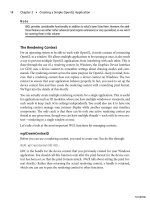
On the CD you will find a Polygons example that illustrates how polygon modes can be
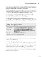
used and the effects they have on OpenGL drawing. Figure 3.5 is a screenshot of this
example.
In this example, we have five squares rotating clockwise at the same rate, which means the
front faces of the squares face the same direction at the same time (and vice versa for the
back faces). Each square is given a different polygon mode and is therefore drawn differ-
ently. Starting from the left (square number one), here is each square’s configuration:
1)
glPolygonMode(GL_FRONT, GL_LINE);
2)
glPolygonMode(GL_BACK, GL_POINT);
3)
glPolygonMode(GL_FRONT_AND_BACK, GL_FILL);
4)
glPolygonMode(GL_BACK, GL_LINE);
5)
glPolygonMode(GL_FRONT_AND_BACK, GL_LINE);
Handling Primitives 53
Figure 3.5 Screenshot of the Polygons example in Chapter 3 on the CD.
03 BOGL_GP CH03 3/1/04 2:34 PM Page 53
TLFeBOOK
Polygon Face Culling
Although polygons are infinitely thin, they have two sides, implying that they can be seen
from either side. Sometimes, it makes sense to have each side displayed differently, and
this is why some of the functions presented here require you to specify whether you’re
modifying the front face, back face, or both. In any case, the rendering states for each of
the sides are stored separately.
When you know that the viewer will be able to see only one side of a polygon, it is possi-
ble to have OpenGL eliminate (or more precisely, skip processing) polygons that the
viewer can’t see. For example, with an object that is completely enclosed and opaque, such
as a ball, only the front sides of polygons are ever visible. If you can determine that the
back side of a polygon is facing the viewer (which would be true for polygons on the side
of the ball opposite of the viewer), you can save time transforming and rendering the
polygon because you know it won’t be seen. OpenGL can do this for you automatically
through the process known as culling. To use culling, you first need to enable it by passing
GL_CULL_FACE
to
glEnable()
. Then, you need to specify which face you want culled, which is
done with
glCullFace()
:
void glCullFace(GLenum mode);
mode
can be
GL_FRONT
to cull front facing polygons,
GL_BACK
to cull back facing polygons, or
GL_FRONT_AND_BACK
to cull them both. Choosing the latter causes the polygons to not be
drawn at all, which doesn’t seem particularly useful.
GL_BACK
is the default setting.
The next step is telling OpenGL how to determine whether a polygon is front facing or
back facing. It does this based on what is called polygon winding, which is the order in
which you specify vertices. Looking at a polygon head-on, you can choose any vertex with
which to begin describing it. To finish describing it, you have to proceed either clockwise
or counterclockwise around its vertices. If you’re consistent about how you specify your
polygons and order your vertices, OpenGL can use the winding to automatically deter-
mine whether a polygon face is front or back facing. By default, OpenGL treats polygons
with counterclockwise ordering as front-facing and polygons with clockwise ordering as
back-facing. The default behavior can be changed using
glFrontFace()
:
void glFrontFace(GLenum mode);
mode
should be
GL_CCW
if you want to use counterclockwise orientation for front-facing
polygons and
GL_CW
if you want to use clockwise orientation.
Note
The winding setting isn’t just relevant in culling; it’s used by other OpenGL subsystems, including
lighting.
Chapter 3
■
OpenGL States and Primitives54
03 BOGL_GP CH03 3/1/04 2:34 PM Page 54
TLFeBOOK
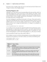
Hiding Polygon Edges
It’s not uncommon to want to render something in wire-frame mode, and sometimes you
may not want to have all the edges of your polygons show up. For example, if you’re draw-
ing a square using two triangles, you may not want the viewer to see the diagonal line. This
is illustrated in Figure 3.6.
You can tell OpenGL whether a particular edge of a polygon should be included when ren-
dering it as lines by calling
glEdgeFlag()
, which can take on one of the two following forms:
■
void glEdgeFlag(GLboolean isEdge);
■
void glEdgeFlagv(const GLboolean *isEdge);
The only difference between these two forms is that the first takes a single Boolean value
as its parameter and the second takes a pointer to an array containing a single Boolean
value. (The OpenGL designers must have had a good reason to want to pass a single value
in an array, but I can’t think of one myself!) Either way, these functions are used to set the
edge flag. If the flag is set to
GL_TRUE
(the default), the edges you specify are drawn; if it is
set to
GL_FALSE
, they are not. Pretty simple.
Antialiasing Polygons
As with points and lines, you can also choose to antialias polygons. You control polygon
antialiasing by passing
GL_POLYGON_SMOOTH
to
glEnable()
and
glDisable()
, and the current
state can be determined by passing the same parameter to
glGet()
or
glIsEnabled()
. As you
might expect, it is disabled by default. Here is an example of how to enable polygon
antialiasing:
// if polygon antialiasing is disabled, then enable it
if (!glIsEnabled(GL_POLYGON_SMOOTH))
glEnable(GL_POLYGON_SMOOTH);
Handling Primitives 55
Figure 3.6 Hiding polygon edges you don’t want to see.
03 BOGL_GP CH03 3/1/04 2:34 PM Page 55
TLFeBOOK
Specifying a Stipple Pattern
The last general polygon attribute you need to look at is polygon stippling, which is sim-
ilar to line stippling. Rather than filling in a polygon with a solid color, you can set a stip-
ple pattern to fill the polygon. If you’ve ever set a pattern for your Windows wallpaper,
you’ll have some idea of the effect.
Polygon stippling is off by default, but you can turn it on by passing
GL_POLYGON_STIPPLE
to
glEnable()
. Once it’s enabled, you need to specify a stipple pattern, which you do using the
following:
void glPolygonStipple(const GLubyte *mask);
The
mask
parameter in this call is a pointer to an array containing a 32 × 32 bit pattern. This
mask will be used to determine which pixels show up (for bits that are turned on) and which
ones don’t. Unlike line-stipple patterns, which show up in reverse, polygon-stipple patterns
show up exactly as they are specified. Note that the stipple pattern is applied to screen coor-
dinates in 2D. Thus, rotating a polygon doesn’t rotate the pattern as well.
Now that we’ve discussed some general polygon properties, we can look at specific polyg-
onal primitives supported by OpenGL.
Triangles
Triangles are generally the preferred polygon form. There are several reasons for this:
■
The vertices of a polygon are always coplanar, because three points define a plane.
■
A triangle is always convex.
■
A triangle can’t cross over itself.
If you try to render a polygon that violates any of these three properties, unpredictable
behavior will result. Because any polygon can be broken down into a number of triangles,
it makes sense to work with them.
Drawing a triangle in 3D isn’t any more difficult than drawing a point or a line. You just
need to change the value passed to
glBegin()
and then specify three vertices:
glBegin(GL_TRIANGLES);
glVertex3f(-2.0, -1.0, 0.0);
glVertex3f(3.0, 1.0, 0.0);
glVertex3f(0.0, 3.0, 0.0);
glEnd();
Just as with points and lines, you can draw multiple triangles at one time. OpenGL treats
every vertex triple as a separate triangle. If the number of vertices defined isn’t a multiple
of 3, then the extra vertices are discarded.
Chapter 3
■
OpenGL States and Primitives56
03 BOGL_GP CH03 3/1/04 2:34 PM Page 56
TLFeBOOK
OpenGL also supports a couple of primitives related to triangles that can improve per-
formance. To understand why you might want to use these, consider Figure 3.7.
Here, you have two connected triangles, which have vertices A and C in common. If you
render these using
GL_TRIANGLES
, you’ll have to specify a total of six vertices (A, B, and C for
triangle 1 and A, D, and C for triangle 2). You’ll send A and C down the pipeline twice,
performing the same geometrical operations on them each time. Obviously, this is waste-
ful; compounding this, you can have vertices shared by many triangles in more complex
models. If you can reduce the number of times you’re sending and transforming redun-
dant vertices, you can improve performance, which is always good.
One way you can do this is by using triangle strips. Simply call
glBegin()
with
GL_TRIANGLE_STRIP
, followed by a series of vertices. OpenGL handles this by drawing the
first three vertices as a single triangle; after that, it takes every vertex specified and combines
it with the previous two vertices to create another triangle. This means that after the first
triangle, each additional triangle costs only a single vertex. In general, every set of n trian-
gles you can reduce to a triangle strip reduces the number of vertices from 3n to n + 2.
Figure 3.8 illustrates how you can use a triangle strip.
Triangle fans are a similar concept; you can visualize them as a series of triangles around
a single central vertex. You draw fans by calling
glBegin()
with
GL_TRIANGLE_FAN
. The first
vertex specified is the central vertex, and every following adjacent pair of vertices is com-
bined with the center vertex to create a new polygon, as illustrated in Figure 3.9.
Handling Primitives 57
Figure 3.7 Two polygons with shared vertices.
03 BOGL_GP CH03 3/1/04 2:34 PM Page 57
TLFeBOOK
Chapter 3
■
OpenGL States and Primitives58
Figure 3.8 A triangle strip creates triangles by combining vertices
into triplet sets.
Figure 3.9 A triangle fan starts with the central vertex and spans
out as a “fan” of vertices.
03 BOGL_GP CH03 3/1/04 2:34 PM Page 58
TLFeBOOK
Like strips, fans allow you to draw n triangles while specifying only n + 2 vertices. How-
ever, in practice, the number of triangles that can be packed into a single fan is usually
considerably fewer than the number that can be represented as a strip because in most
cases, any given vertex won’t be shared by a huge number of triangles.
The challenge with either method is in identifying strips and fans, which is relatively easy
with simple models but becomes increasingly difficult as the complexity of your models
grows. Normally, the process of converting a model represented as triangles into a series
of triangle strips (or fans, but usually strips) is done outside of your game engine, either
when the model is exported from a modeling program or through a separate tool that
optimizes the data for your game. Doing this effectively is beyond the scope of our cur-
rent discussion.
Quadrilaterals
Quadrilaterals, or quads, are four-sided polygons that can be convenient when you want
to draw a square or rectangle. You create them by calling
glBegin()
with
GL_QUADS
and then
specifying four or more vertices, as Figure 3.10 shows. Like triangles, you can draw as
many quads as you want at a time.
Handling Primitives 59
Figure 3.10 A quad is specified with four vertices.
03 BOGL_GP CH03 3/1/04 2:34 PM Page 59
TLFeBOOK
OpenGL provides quad strips as a means of improving the speed of rendering quads.
They are specified using
GL_QUAD_STRIP
. Each pair of vertices specified after the first pair
defines a new quad.
Polygons
OpenGL also supports polygons with an arbitrary number of vertices, but in such cases,
only one polygon can be drawn within a
glBegin()
/
glEnd()
block. The parameter passed is
GL_POLYGON
(notice that it’s not plural), and once
glEnd()
is reached, the last vertex is auto-
matically connected to the first. If fewer than three vertices are specified, nothing is
drawn. Figure 3.11 is an example of polygon drawing.
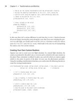
Using Primitives: Triangles and Quads Example
The final example for this chapter, called TrianglesQuads, shows how you can render a
grid using variations of triangles and quads. You can see the screenshot of this example in
Figure 3.12.
Chapter 3
■
OpenGL States and Primitives60
Figure 3.11 A polygon can be an arbitrary number of vertices.
03 BOGL_GP CH03 3/1/04 2:34 PM Page 60
TLFeBOOK
As you can see in the screenshot, we render a set of six grids, each with a different primi-
tive type. In the top-left of the figure we have a grid drawn with
GL_POINTS
so you can see
the shape of the grid. The code for drawing this is simply:
void DrawPoints()
{
glPointSize(4.0);
glBegin(GL_POINTS);
for (int x = 0; x < 4; x++)
for (int z = 0; z < 4; z++)
glVertex3f(x, 0, z);
glEnd();
}
The top-middle grid is drawn with
GL_TRIANGLES
. We used
GL_FILL
on this grid so you can
see where the actual triangles are drawn (in all other grids the entire grid is filled). The
code for this grid is
void DrawTriangles()
{
glBegin(GL_TRIANGLES);
Handling Primitives 61
Figure 3.12 Screenshot of the TrianglesQuads example in Chapter 3
on the CD.
03 BOGL_GP CH03 3/1/04 2:34 PM Page 61
TLFeBOOK
for (int x = 0; x < 3; x++)
{
for (int z = 0; z < 3; z++)
{
glVertex3f(x, 0.0, z);
glVertex3f((x+1.0), 0.0, z);
glVertex3f(x, 0.0, (z+1.0));
}
}
glEnd();
}
The top–right grid is drawn with
GL_QUADS
. The code for this grid is
void DrawQuads()
{
glBegin(GL_QUADS);
for (int x = 0; x < 3; x++)
{
for (int z = 0; z < 3; z++)
{
glVertex3f(x, 0.0, z);
glVertex3f((x+1.0), 0.0, z);
glVertex3f((x+1.0), 0.0, (z+1.0));
glVertex3f(x, 0.0, (z+1.0));
}
}
glEnd();
}
The bottom-left grid is drawn with rows of
GL_TRIANGLE_STRIP
. The code for this grid is
void DrawTriangleStrip()
{
// 3 rows of triangle strips
for (int x = 0; x < 3; x++)
{
glBegin(GL_TRIANGLE_STRIP);
for (int z = 0; z < 3; z++)
{
glVertex3f(x, 0.0, z);
glVertex3f((x+1.0), 0.0, z);
glVertex3f(x, 0.0, (z+1.0));
Chapter 3
■
OpenGL States and Primitives62
03 BOGL_GP CH03 3/1/04 2:34 PM Page 62
TLFeBOOK
glVertex3f((x+1.0), 0.0, (z+1.0));
}
glEnd();
}
}
The bottom-middle grid is drawn with a
GL_TRIANGLE_FAN
. The code for this grid is
void DrawTriangleFan()
{
glBegin(GL_TRIANGLE_FAN);
// center vertex of fan
glVertex3f(0.0, 0.0, 0.0);
// bottom side
for (int x = 4; x > 0; x—)
glVertex3f(x-1, 0.0, 3.0);
// right side
for (int z = 4; z > 0; z—)
glVertex3f(3.0, 0.0, z-1);
glEnd();
}
And finally, the bottom-right grid is drawn with rows of
GL_QUAD_STRIP
. The code for this
grid is
void DrawQuadStrip()
{
for (int x = 0; x < 3; x++)
{
glBegin(GL_QUAD_STRIP);
for (int z = 0; z < 4; z++)
{
glVertex3f(x, 0.0, z);
glVertex3f((x+1.0), 0.0, z);
}
glEnd();
}
}
Handling Primitives 63
03 BOGL_GP CH03 3/1/04 2:34 PM Page 63
TLFeBOOK
As you can see from the code, each grid’s code is slightly different from the others. This is
because each primitive accepts data slightly differently, which requires us to modify our
algorithms for each primitive type in order for the grids to be drawn properly.
Spend some time looking at and modifying this code to be sure you are comfortable with
it. You will be using primitives in every application from here on out, so you had better
understand them well!
Attributes
Earlier in this chapter you saw how to set and query individual states from OpenGL. Now
let us look at a way to save and restore the values of a set of related state variables with a
single command.
An attribute group is a set of related state variables that OpenGL classifies into a group.
For example, the line group consists of all the line drawing attributes, such as the width,
stipple pattern attributes, and line smoothing. The polygon group consists of the
same sets of attributes as lines, except for polygons. By using the
glPushAttrib()
and
glPopAttrib()
functions, you can save and restore all of the state information for a group
in one function call.
void glPushAttrib(GLbitfield mask);
void glPopAttrib(void);
glPushAttrib()
saves all of the attributes for the attribute group specified by
mask
onto the
attribute stack. The mask bits can be logically ORed together to save any combination of
attribute bits.
glPopAttrib()
restores the values of the state variables that were saved with
the last
glPushAttrib()
. Table 3.8 includes a list of a few (certainly not all!) attribute groups
that you can pass to
glPushAttrib()
.
Chapter 3
■
OpenGL States and Primitives64
Table 3.8 Attribute Groups
Mask Attribute Group
GL_ALL_ATTRIB_BITS
All OpenGL state variables in all attribute groups
GL_ENABLE_BIT
Enabled state variables
GL_FOG_BIT
Fog state variables
GL_LIGHTING_BIT
Lighting state variables
GL_LINE_BIT
Line state variables
GL_POINT_BIT
Point state variables
GL_POLYGON_BIT
Polygon state variables
GL_TEXTURE_BIT
Texturing state variables
03 BOGL_GP CH03 3/1/04 2:34 PM Page 64
TLFeBOOK
Summary
In this chapter, you learned a little more about the OpenGL state machine. You know how
to use
glGet()
and
glIsEnabled()
to query the values of parameters within the state
machine. You’ve also seen some specialized functions for altering the state machine, and
you should now have an idea of how it works. You’ll be looking at other aspects of the state
machine as you move on.
You also learned about the primitive types supported by OpenGL and how to modify
properties pertaining to them. You should now have no trouble putting points, lines, tri-
angles, and other primitives on the screen. Now that you have state machine basics and
primitives under your belt, you can safely move on to more interesting things.
What You Have Learned
■
You can query current settings from the OpenGL state machine by using the
glGet()
and
glIsEnabled()
functions.
■
Primitives are drawn by first specifying the primitive type with the
glBegin()
func-
tion, then sending the vertices and following up with the
glEnd()
function.
■
The
glVertex()
function specifies a vertex in a
glBegin()
/
glEnd()
block and is avail-
able in several variations that allow you to define the number of coordinates, the
coordinates’ data type, and whether the coordinates are being passed individually
or as an array.
■
You can draw points by passing
GL_POINTS
as the parameter to
glBegin()
, modify
point size by using the
glPointSize()
function, turn point antialiasing on by passing
GL_POINT_SMOOTH
to
glEnable()
, and control the effect of distance on points with
glPointParameter()
.
■
Lines are drawn by passing
GL_LINES
as the parameter to
glBegin()
. You can modify
line width with the
glLineWidth()
function, and line antialiasing is turned on by
sending
GL_LINE_SMOOTH
to
glEnable()
. Line stippling is accomplished through the
use of the
glLineStipple()
function.
■
You can change the way OpenGL draws polygons by using the
glPolygonMode()
function. Passing
GL_POINT
forces OpenGL to draw only the vertices of polygons;
GL_LINE
forces OpenGL to draw the edges between polygon vertices as lines;
GL_FILL
is the default behavior, which renders polygons with the interior filled and allows
polygon smoothing and stippling.
■
Passing
GL_CULL_FACE
to
glEnable()
tells OpenGL to enable its face culling mecha-
nism. Using the
glCullFace()
function then allows you to specify which polygon
side OpenGL should cull.
Summary 65
03 BOGL_GP CH03 3/1/04 2:34 PM Page 65
TLFeBOOK
■
By default, OpenGL treats vertices that are ordered counterclockwise in a polygon
as the front face of the polygon, while the clockwise vertices are the back face. The
glFrontFace()
function allows you to modify this setting.
■
Triangles are the most important polygon in 3D graphics as any polygon can be
broken down into a set of triangles. You draw a triangle in OpenGL by passing
GL_TRIANGLES
to
glBegin()
.
■
You can draw a set of triangles more efficiently by passing
GL_TRIANGLE_STRIP
or
GL_TRIANGLE_FAN
to
glBegin()
.
GL_TRIANGLE_STRIP
draws a triangle strip, which creates a
strip of triangles by combining vertices into sets of triplets.
GL_TRIANGLE_FAN
starts
with the first vertex as the center vertex and draws the rest as a fan of vertices
around the center.
■
Quadrilaterals may also be drawn by passing
GL_QUADS
or
GL_QUAD_STRIP
to
glBegin()
.
■
n-sided convex polygons may be drawn by passing
GL_POLYGON
to
glBegin()
.
■
You can save and restore OpenGL state variables using the
glPushAttrib()
and
glPopAttrib()
functions.
Review Questions
1. How would you determine if OpenGL is drawing antialiased lines?
2. How is culling enabled?
3. In what order does OpenGL draw vertices for a
GL_TRIANGLE_STRIP
?
4. In what order does OpenGL draw vertices for a
GL_TRIANGLE_FAN
?
5. What do the following variations of
glVertex()
mean?
a.
glVertex3f()
b.
glVertex2iv()
c.
glVertex4d()
d.
glVertex3fv()
e.
glVertex2s()
On Your Own
1. You have been tasked to write a function that draws a 2D circle approximation
with the option of drawing only the edge of the circle or drawing the circle filled at
the world origin (0, 0, 0). Your function must accept the radius of the circle and a
value for the number of edges in the circle approximation. Write a function to
draw the circle approximation given the following prototype:
void DrawCircleApproximation(float radius, int numberOfSides, bool edgeOnly);
Chapter 3
■
OpenGL States and Primitives66
03 BOGL_GP CH03 3/1/04 2:34 PM Page 66
TLFeBOOK
67
Transformations
and Matrices
chapter 4
N
ow it’s time to take a short break from learning how to create objects in the
world and focus on learning how to move the objects around in the world. This
is a vital ingredient to generating realistic 3D gaming worlds; without it, the 3D
scenes you create would be static, boring, and totally noninteractive. OpenGL makes it
easy for the programmer to move objects around through the use of various coordinate
transformations, discussed in this chapter. You will also take a look at how to use your own
matrices with OpenGL, which provides you with the power to manipulate objects in many
different ways.
In this chapter you’ll learn about:
■
The basics of coordinate transformations
■
The camera and viewing transformations
■
OpenGL matrices and matrix stacks
■
Projections
■
Using your own matrices with OpenGL
Understanding Coordinate Transformations
Set this book down and stop reading for a moment. Look around you. Now, imagine that
you have a camera in your hands, and you are taking photographs of your surroundings.
For instance, you might be in an office and have your walls, this book, your desk, and
maybe your computer near you. Each of these objects has a shape and geometry described
04 BOGL_GP CH04 3/1/04 9:58 AM Page 67
TLFeBOOK
in a local coordinate system, which is unique for every object, is centered on the object, and
doesn’t depend on any other objects. They also have some sort of position and orienta-
tion in the world space. You have a position and orientation in world space as well. The
relationship between the positions of these objects around you and your position and ori-
entation determines whether the objects are behind you or in front of you. As you are tak-
ing photographs of these objects, the lens of the camera also has some effect on the final
outcome of the pictures you are taking. A zoom lens makes objects appear closer to or
farther from your position. You aim and click, and the picture is “rendered” onto the cam-
era film (or onto your memory card if you have a digital camera). Your camera and its film
also have settings, such as size and resolution, which help define how the final picture is
rendered. The final image you see in a picture is a product of how each object’s position,
your position, your camera’s lens, and your camera’s settings interact to map your sur-
rounding objects’ three-dimensional features to the two-dimensional picture.
Transformations work the same way. They allow you to move, rotate, and manipulate
objects in a 3D world, while also allowing you to project 3D coordinates onto a 2D screen.
Although transformations seem to modify an object directly, in reality, they are merely
transforming the object’s local coordinate system into another coordinate system. When
rendering 3D scenes, vertices pass through four types of transformations before they are
finally rendered on the screen:
■
Modeling transformation. The modeling transformation moves objects around
the scene and moves objects from local coordinates into world coordinates.
■
Viewing transformation. The viewing transformation specifies the location of the
camera and moves objects from world coordinates into eye or camera coordinates.
■
Projection transformation. The projection transformation defines the viewing
volume and clipping planes and maps objects from eye coordinates to clip
coordinates.
■
Viewport transformation. The viewport transformation maps the clip coordinates
into the two-dimensional viewport, or window, on your screen.
While these four transformations are standard in 3D graphics, OpenGL includes and
combines the modeling and viewing transformation into a single modelview transforma-
tion. We will discuss the modelview transformation in “The Modelview Matrix” section of
this chapter.
Table 4.1 shows a summary of all these transformations.
When you are writing your 3D programs, remember that these transformations execute
in a specific order. The modelview transformations execute before the projection trans-
formations; however, the viewport can be specified at any time, and OpenGL will auto-
matically apply it appropriately. Figure 4.1 shows the general order in which these vertex
transformations are executed.
Chapter 4
■
Transformations and Matrices68
04 BOGL_GP CH04 3/1/04 9:58 AM Page 68
TLFeBOOK
Eye Coordinates
One of the most critical concepts to transformations and viewing in OpenGL is the con-
cept of the camera, or eye coordinates. In 3D graphics, the current viewing transforma-
tion matrix, which converts world coordinates to eye coordinates, defines the camera’s
position and orientation. In contrast, OpenGL converts world coordinates to eye coordi-
nates with the modelview matrix. When an object is in eye coordinates, the geometric rela-
tionship between the object and the camera is known, which means our objects are
positioned relative to the camera position and are ready to be rendered properly. Essen-
tially, you can use the viewing transformation to move a camera about the 3D world,
while the modeling transformation moves objects around the world. In OpenGL, the
default camera (or viewing matrix transformation) is always oriented to look down the
negative z axis, as shown in Figure 4.2.
Understanding Coordinate Transformations 69
Figure 4.1 The vertex transformation pipeline.
Table 4.1 OpenGL Transformations
Transformation Description
Viewing In 3D graphics, specifies the location of the camera (not a true OpenGL
transformation)
Modeling In 3D graphics, handles moving objects around the scene (not a true OpenGL
transformation)
Projection Defines the viewing volume and clipping planes
Viewport Maps the projection of the scene into the rendering window
Modelview Combination of the viewing and modeling transformations
04 BOGL_GP CH04 3/1/04 9:58 AM Page 69
TLFeBOOK
To give you an idea of this orientation, imagine that you are at the origin and you rotate
to the left 90 degrees (about the y axis); you would then be facing along the negative x axis.
Similarly, if you were to place yourself in the default camera orientation and rotate 180
degrees, you would be facing in the positive z direction.
Viewing Transformations
The viewing transformation is used to position and aim the camera. As already stated, the
camera’s default orientation is to point down the negative z axis while positioned at the
origin (0,0,0). You can move and change the camera’s orientation through translation and
rotation commands, which, in effect, manipulate the viewing transformation.
Remember that the viewing transformation must be specified before any other modeling
transformations. This is because transformations in OpenGL are applied in reverse order.
By specifying the viewing transformation first, you are ensuring that it gets applied after
the modeling transformations.
How do you create the viewing transformation? First you need to clear the current matrix.
You accomplish this through the
glLoadIdentity()
function, specified as
void glLoadIdentity();
Chapter 4
■
Transformations and Matrices70
Figure 4.2 The default viewing matrix in OpenGL looks down the
negative z axis.
04 BOGL_GP CH04 3/1/04 9:58 AM Page 70
TLFeBOOK
This sets the current matrix equal to the identity matrix and is analogous to clearing the
screen before beginning rendering.
Tip
The identity matrix is the matrix in which the diagonal element values in the matrix are equal to
1, and all the other (nondiagonal) element values in the matrix are equal to 0, so that given the
4 × 4 matrix
M
:
M
(0,0) =
M
(1,1) =
M
(2,2) =
M
(3,3) = 1. Multiplying the identity matrix
I
by a matrix
M
results in a matrix equal to
M
, such that
I
×
M
=
M
.
After initializing the current matrix, you can create the viewing matrix in several different
ways. One method is to leave the viewing matrix equal to the identity matrix. This results
in the default location and orientation of the camera, which would be at the origin and
looking down the negative z axis. Other methods include the following:
■
Using the
gluLookAt()
function to specify a line of sight that extends from the
camera. This is a function that encapsulates a set of translation and rotation
commands and will be discussed later in this chapter in the “Using
gluLookAt()
”
section.
■
Using the translation and rotation modeling commands
glTranslate()
and
glRotate()
. These commands are discussed in more detail in the “Using
glRotate()
and
glTranslate()
” section in this chapter; for now, suffice it to say that this
method moves the objects in the world relative to a stationary camera.
■
Creating your own routines that use the translation and rotation functions for
your own coordinate system (for example, polar coordinates for a camera orbiting
around an object). This concept will be discussed in this chapter in the “Creating
Your Own Custom Routines” section.
Modeling Transformations
The modeling transformations allow you to position and orient a model by moving,
rotating, and scaling it. You can perform these operations one at a time or as a combina-
tion of events. Figure 4.3 illustrates the three built-in operations that you can use on
objects:
■
Translation. This operation is the act of moving an object along a specified vector.
■
Rotation. This is where an object is rotated about a vector.
■
Scaling. This is when you increase or decrease the size of an object. With scaling,
you can specify different values for different axes. This gives you the ability to
stretch and shrink objects non-uniformly.
The order in which you specify modeling transformations is very important to the final
rendition of your scene. For example, as shown in Figure 4.4, rotating and then translating
Understanding Coordinate Transformations 71
04 BOGL_GP CH04 3/1/04 9:58 AM Page 71
TLFeBOOK
an object has a completely different effect than translating and then rotating the object.
Let’s say you have an arrow located at the origin that lies flat on the x-y plane, and the first
transformation you apply is a rotation of 30 degrees around the z axis. You then apply a
Chapter 4
■
Transformations and Matrices72
Figure 4.3 The three modeling transformations.
Figure 4.4 (A) Performing rotation before translation; (B) Performing
translation before rotation.
04 BOGL_GP CH04 3/1/04 9:58 AM Page 72
TLFeBOOK
translation transformation of +5 units along the x axis. The final position of the triangle
would be (5, 4.33) with the arrow pointing at a 30-degree angle from the positive x axis.
Now, let’s swap the order and say you translate the arrow by +5 units along the x axis first.
Then you rotate the arrow 30 degrees about the z axis. After the translation, the arrow
would be located at (5, 0). When you apply the rotation transformation, the arrow would
still be located at (5, 0), but it would be pointing at a 30-degree angle from the x axis.
Projection Transformations
The projection transformation defines the viewing volume and clipping planes. It is per-
formed after the modeling and viewing transformations. You can think of the projection
transformation as determining which objects belong in the viewing volume and how they
should look. It is very much like choosing a camera lens that is used to look into the world.
The field of view you choose when creating the projection transformation determines
what type of lens you have. For instance, a wider field of view would be like having a wide-
angle lens, where you could see a huge area of the scene without much detail. With a
smaller field of view, which would be similar to a telephoto lens, you would be able to look
at objects as though they were closer to you than they actually are.
OpenGL offers two types of projections:
■
Perspective projection. This type of projection shows 3D worlds exactly as you see
things in real life. With perspective projection, objects that are farther away appear
smaller than objects that are closer to the camera.
■
Orthographic projection. This type of projection shows objects on the screen in
their true size, regardless of their distance from the camera. This projection is use-
ful for CAD software, where objects are drawn with specific views to show the
dimensions of an object (i.e. front, left, top views), and can also be used for iso-
metric games.
Viewport Transformations
The last transformation is the viewport transformation. This transformation maps the clip
coordinates created by the perspective transformation onto your window’s rendering sur-
face. You can think of the viewport transformation as determining whether the final
image should be enlarged or shrunk, depending on the size of the rendering surface.
OpenGL and Matrices
Now that you’ve learned about the various transformations involved in OpenGL, let’s take
a look at how you actually use them. Transformations in OpenGL rely on the matrix for
all mathematical computations. As you will soon see, OpenGL has what is called the
OpenGL and Matrices 73
04 BOGL_GP CH04 3/1/04 9:58 AM Page 73
TLFeBOOK
matrix stack, which is useful for constructing complicated models composed of many
simple objects. You will be taking a look at each of the transformations and look more into
the matrix stack in this section.
Tip
In case you need a refresher course, the mathematical concept of the matrix is discussed in the “3D
Theory and Concepts” chapter included on the CD.
The Modelview Matrix
The modelview matrix defines the coordinate system that is used to place and orient
objects. This 4 × 4 matrix can either transform vertices or it can be transformed itself by
other matrices. Vertices are transformed by multiplying a vertex vector by the modelview
matrix, resulting in a new vertex vector that has been transformed. The modelview matrix
itself can be transformed by multiplying it by another 4 × 4 matrix.
Before calling any transformation commands, you must specify whether you want to
modify the modelview matrix or the projection matrix. Modifying either matrix is accom-
plished through the OpenGL function
glMatrixMode()
, which is defined as
void glMatrixMode(GLenum mode);
In order to modify the modelview matrix, you use the argument
GL_MODELVIEW
. This sets the
modelview matrix to the current matrix, which means that it will be modified with sub-
sequent transformation commands. Doing this looks like
void glMatrixMode(GL_MODELVIEW);
Other arguments for
glMatrixMode
include
GL_PROJECTION
,
GL_COLOR
,or
GL_TEXTURE
.
GL_
PROJECTION
is used to specify the projection matrix;
GL_COLOR
is used to indicate the color
matrix, which we won’t be covering; and
GL_TEXTURE
is used to indicate the texture matrix,
which we will discuss in Chapter 7, “Texture Mapping.”
Usually at the beginning of your rendering loop, you will want to reset the modelview
matrix to the default position (0, 0, 0) and orientation (looking down the negative z axis).
To do this, you call the
glLoadIdentity()
function, which loads the identity matrix as the
current modelview matrix, thereby positioning the camera at the world origin and default
orientation. Here’s a snippet of how you might reset the modelview matrix:
glMatrixMode(GL_MODELVIEW);
glLoadIdentity(); // reset the modelview matrix
// do other transformations
Chapter 4
■
Transformations and Matrices74
04 BOGL_GP CH04 3/1/04 9:58 AM Page 74
TLFeBOOK
Translation
Translation allows you to move an object from one position in the world to another posi-
tion in the world. The OpenGL function
glTranslate()
performs this functionality and is
defined as follows:
void glTranslate{fd}(TYPE x, TYPE y, TYPE z);
The parameters
x
,
y
, and
z
specify the amount to translate along the x, y, and z axes. For
example, if you execute the command
glTranslatef(3.0f, 1.0f, 8.0f);
any subsequently specified objects will be moved three units along the positive x axis, one
unit along the positive y axis, and eight units along the positive z axis, to a final position
of (3, 1, 8).
Suppose you want to move a cube from the origin to the position (5, 5, 5). You first load
the modelview matrix and reset it to the identity matrix, so you are starting at the origin
(0, 0, 0). You then perform the translation transformation on the current matrix to posi-
tion (5, 5, 5) before calling your
DrawCube()
function. In code, this looks like
glMatrixMode(GL_MODELVIEW); // set current matrix to modelview
glLoadIdentity(); // reset modelview to identity matrix
glTranslatef(5.0f, 5.0f, 5.0f); // move to (5,5,5)
DrawCube(); // draw the cube
Figure 4.5 illustrates how this code executes.
OpenGL and Matrices 75
Figure 4.5 Translating a cube from the origin to (5,5,5).
04 BOGL_GP CH04 3/1/04 9:58 AM Page 75
TLFeBOOK
How about a translation example? On the CD under Chapter 4 you will find an example
called Translation that illustrates a very simple oscillating translation along the z axis. The
example renders a flat square plane at the origin, but because the world coordinate system
is being translated, the square plane appears to be moving into and away from the view.
Here is the code from the
Prepare()
function, which performs the oscillation logic:
void CGfxOpenGL::Prepare()
{
// if we’re moving in the -z direction, decrement the z position
if (direction)
zPos -= 0.01;
else // we’re moving in the +z direction, increment the z position
zPos += 0.01;
// if we have reached the origin or -20 units along the
// z axis, then change direction
if (zPos >= 0.0)
direction = true;
else if (zPos <= -20.0)
direction = false;
}
This code either increases or decreases the value used to translate the world along the z
axis, depending on the “direction” we are currently heading. When the translation value
reaches an extreme (0.0 or -20.0), then we change the “direction” of the translation. This
code in the
Prepare()
function is called prior to the
Render()
function, which looks like this:
void CGfxOpenGL::Render()
{
// clear color and depth buffers
glClear(GL_COLOR_BUFFER_BIT | GL_DEPTH_BUFFER_BIT);
// load the identity matrix (clear to default position and orientation)
glLoadIdentity();
// translate the world coordinate system along the z axis
glTranslatef(0.0, 0.0, zPos);
// draw the plane at the world origin
DrawPlane();
}
Chapter 4
■
Transformations and Matrices76
04 BOGL_GP CH04 3/1/04 9:58 AM Page 76
TLFeBOOK