beginning opengl game programming 2004 phần 7 docx
Bạn đang xem bản rút gọn của tài liệu. Xem và tải ngay bản đầy đủ của tài liệu tại đây (626.5 KB, 25 trang )
for you. This works in situations where the texture coordinates can be determined using
well-defined mathematical steps. Examples include reflections, contouring, and projective
texturing. We’ll be discussing a couple of specific examples here.
Texture coordinate generation is controlled independently for each coordinate. To use it,
you must first enable it by passing
GL_TEXTURE_GEN_S
,
GL_TEXTURE_GEN_T
,
GL_TEXTURE_GEN_R
,or
GL_TEXTURE_GEN_Q
(each corresponding to the indicated coordinate) to
glEnable()
.
To specify how texture coordinates are generated, you use one of the following:
void glTexGen{ifd}(GLenum coord, GLenum pname, TYPE param);
void glTexGen{ifd}v(GLenum coord, GLenum pname, const TYPE *params);
coord
indicates which texture coordinate to apply the parameter to. Valid values are
GL_S
,
GL_T
,
GL_R
, and
GL_Q
, corresponding to the s, t, r, and q texture coordinates. The accepted
values of
pname
and the
param
or
params
associated with them are listed in Table 9.1.
If the texture generation mode is
GL_OBJECT_LINEAR
, then the texture coordinates are gener-
ated using the following equation:
texcoord = p
1
* x
o
+ p
2
* y
o
+ p
3
* z
o
+ p
4
* w
o
x
o
,y
o
,z
o
, and w
o
are the object-space coordinates of the vertex the texture coordinate is
being generated for. p
1
,p
2
,p
3
, and p
4
are the four parameters provided via
GL_OBJECT_PLANE
.
These are used to pass the A, B, C, and D coefficients of a plane, so this equation is in effect
calculating the distance from the plane and using that as the texture coordinate.
The
GL_EYE_LINEAR
texture generation mode uses a similar equation, except that eye-space
vertex coordinates are used, and the inverse modelview matrix is applied to the plane
parameters when they are specified.
Texture Coordinate Generation 203
Table 9.1 Texture Generation Parameters
Parameter Meaning
GL_TEXTURE_GEN_MODE param
specifies the texture generation mode, which must be
GL_OBJECT_LINEAR
,
GL_EYE_LINEAR
,
GL_SPHERE_MAP
,
GL_REFLECTION_MAP
*, or
GL_NORMAL_MAP
*.
GL_OBJECT_PLANE params
is a pointer to a four-element array of values that are used as
parameters for the texture coordinate generation function. Used in conjunction
with
GL_OBJECT_LINEAR
.
GL_EYE_PLANE
Same as above, but used with
GL_EYE_LINEAR
.
* Available only via the
ARB_texture_cube_map
extension under Windows.
09 BOGL_GP CH09 3/1/04 10:04 AM Page 203
TLFeBOOK
When using the
GL_NORMAL_MAP
mode, the (s, t, r) texture coordinates are generated by using
the vertex’s normal, transformed into eye-space. These are intended to be used with cube
maps.
The remaining two texture generation modes will be covered in the next section, but for
now, let’s look at an example of generating texture coordinates based on the distance from
a plane.
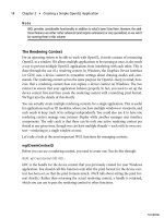
When rendering terrain, you can create a visually appealing effect by varying the color based
on the height of the terrain. Areas close to sea level appear as sand; slightly higher areas
appear as grass, and then dirt or rock, and finally snow on the highest peaks. One way to
achieve this is to create a one-dimensional texture like the one shown in Figure 9.1. Then,
you would enable texture generation based on the height above sea level by passing the coef-
ficients for the sea level plane to
glTexGen()
and enable texture generation for the s coordi-
nate. Later in this chapter, in the “Multitexturing” section, you’ll see a demo that does exactly
that, so let’s look at the code that sets up and uses texture coordinate generation.
First, during initialization, texture coordinate generation is enabled,
GL_OBJECT_LINEAR
mode is selected, and the reference plane is passed via
GL_OBJECT_PLANE
:
glEnable(GL_TEXTURE_GEN_S);
glTexGeni(GL_S, GL_TEXTURE_GEN_MODE, GL_OBJECT_LINEAR);
GLfloat waterPlane[] = { 0.0, 1.0, 0.0, -WATER_HEIGHT };
glTexGenfv(GL_S, GL_OBJECT_PLANE, waterPlane);
Then, when actually rendering the terrain, the only thing that needs to be done is to scale
the generated texture coordinate. This is because the generated coordinate is the distance
from the plane, which could be any value. We want the texture coordinates to fall in the
range [0, 1] so that the lowest points correspond to sand and the highest points corre-
spond to snow. This is simply a matter of dividing the texture coordinate by the maximum
terrain height. Using the texture matrix you learned about in the last section, this is done
as follows:
glMatrixMode(GL_TEXTURE);
glLoadIdentity();
glScalef(1.0f/MAX_HEIGHT, 1.0, 1.0);
Chapter 9
■
More on Texture Mapping204
Figure 9.1 A 1D texture used to color terrain.
09 BOGL_GP CH09 3/1/04 10:04 AM Page 204
TLFeBOOK
That’s all there is to it. Similar methods can be used for creating contours or projective
textures. Now let’s look at the other two texture generation modes.
Environment Mapping
If you’ve ever tried to model things like chrome, polished metal, or glass, you know that
no matter how you tweak the materials or what texture you use, it doesn’t look very much
like the real thing. This is because all of these things reflect the environment they are in,
so to model them correctly, you need to use environment mapping.The
GL_SPHERE_MAP
and
GL_REFLECTION_MAP
texture generation modes can be used in conjunction with an appropri-
ate texture map to create realistic reflections.
For the
GL_SPHERE_MAP
mode, or sphere mapping, the texture coordinates are generated
using a vector from the eye to the point on the surface and the surface normal (trans-
formed into eye space) to create a reflection vector. The reflection vector is used to calcu-
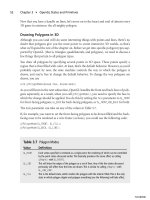
late the texture coordinates. These coordinates are then used to index into a 2D texture
map like that shown in Figure 9.2. The image is a picture of a sphere completely reflect-
ing the world around it. Both the s and t coordinates need to be generated via sphere map-
ping to have it work correctly.
Sphere mapping comes with many drawbacks, one
of the most significant being that it’s view depen-
dent, so viewing a reflective object from anywhere
other than the center of projection can produce
incorrect results. They also tend to not look very
accurate on objects that aren’t roughly spherical.
Finally, obtaining the texture image in the first place
presents a challenge. Traditionally, they were
obtained by taking a photograph of a perfectly
reflective sphere placed in the room that is being
modeled. For this to be completely mathematically
correct, the camera needs to be infinitely far away,
but since this is impossible, a fish eye lens is used
instead to get results that are reasonably close. This
approach isn’t really viable for game environments.
Another drawback is that the reflection won’t pick up any objects moving in the world, so
it will be immediately obvious that the surface isn’t really reflective.
An alternative way to generate the texture image is to render the world six times (once for
each direction) from the reflective object’s perspective. The results are then stored in the
six faces of a cube map, which is then applied to a sphere. This is actually how the image
in Figure 9.2 was generated. This approach is much better, since a reflection image can be
generated anywhere in your world, and it can be updated dynamically to reflect objects in
Texture Coordinate Generation 205
Figure 9.2 A typical texture used
with
GL_SPHERE_MAP
.
09 BOGL_GP CH09 3/1/04 10:04 AM Page 205
TLFeBOOK
motion. However, as you’re about to see, you can make use of the cube map directly, so
the additional step of generating a sphere map is wasteful. Cube maps are also view inde-
pendent and can be easily mapped onto any objects. For these reasons, sphere mapping is
generally not used anymore.
When cube map textures were introduced to OpenGL, they brought with them the
GL_REFLECTION_MAP
texture coordinate generation mode. The texture coordinates are gener-
ated in a manner similar to
GL_SPHERE_MAP
, except that instead of creating s and t coordi-
nates for a 2D texture, s, t, and r coordinates are generated that are used to index into the
faces of the cube map. Cube maps are much easier to update dynamically and do a better
job of capturing the entire environment. The example in the next section shows you how
cube maps can be used for reflections.
Example: Reflective Cube Mapping
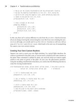
On the CD, you’ll find an example program for this chapter entitled EnvironmentMap-
ping, that puts reflective cube maps to use. As you can see from Figure 9.3, this program
shows a reflective sphere that is being orbited by two colored balls, placed in an outdoor
environment. In the “Copying from the Color Buffer” section earlier in this chapter, you
saw the portion of this code that creates the faces of the cube map texture by
Chapter 9
■
More on Texture Mapping206
Figure 9.3 A reflective sphere, made possible with cube maps and
reflection mapping.
09 BOGL_GP CH09 3/1/04 10:04 AM Page 206
TLFeBOOK
rendering the scene six times from the perspective of the sphere. The cube map is then
applied to the sphere using texture coordinate generation. To do this, the texture genera-
tion mode is first set up during initialization, as follows:
glTexGenf(GL_S, GL_TEXTURE_GEN_MODE, GL_REFLECTION_MAP);
glTexGenf(GL_T, GL_TEXTURE_GEN_MODE, GL_REFLECTION_MAP);
glTexGenf(GL_R, GL_TEXTURE_GEN_MODE, GL_REFLECTION_MAP);
Then, to actually apply the texture to the sphere, texture coordinate generation for the s, t
and r coordinates has to be enabled. This happens in the
Render()
method, as shown below:
void CGfxOpenGL::Render()
{
GenerateEnvTexture();
glClear(GL_DEPTH_BUFFER_BIT);
glLoadIdentity();
m_skybox.Render(0.0, 0.0, 0.0);
glTranslatef(0.0, 0.0, -5.0);
GLfloat lightPos[] = { 0.5f, 0.5, 1.0, 0.0 };
glLightfv(GL_LIGHT0, GL_POSITION, lightPos);
glEnable(GL_TEXTURE_GEN_S);
glEnable(GL_TEXTURE_GEN_T);
glEnable(GL_TEXTURE_GEN_R);
glEnable(GL_TEXTURE_CUBE_MAP);
glBindTexture(GL_TEXTURE_CUBE_MAP, m_envTexID);
glTexEnvf(GL_TEXTURE_ENV, GL_TEXTURE_ENV_MODE, GL_MODULATE);
glColor3f(1.0f, 1.0f, 1.0f);
gluSphere(m_pObj, 1.0, 64, 64);
glDisable(GL_TEXTURE_CUBE_MAP);
glDisable(GL_TEXTURE_GEN_S);
glDisable(GL_TEXTURE_GEN_T);
glDisable(GL_TEXTURE_GEN_R);
DrawBalls();
}
Texture Coordinate Generation 207
09 BOGL_GP CH09 3/1/04 10:04 AM Page 207
TLFeBOOK
As you can see, creating dynamic reflections with cube maps is quite easy. The cost involved
is not trivial because it requires that the scene be rendered an additional six times per
reflective object. When used in moderation however, the visual payoff is worth it.
Multitexturing
Extension
Extension name:
ARB_multitexture
Name string:
GL_ARB_multitexture
Promoted to core: OpenGL 1.2.1
Function names:
glActiveTextureARB()
,
glMultiTexCoord{1234}{sifd}[v]ARB()
Tokens:
GL_TEXTUREn_ARB
,
GL_MAX_TEXTURE_UNITS_ARB
In the examples you’ve seen so far, when you texture-map a polygon, you apply only one
texture to it. It’s actually possible to apply several textures to the same polygon through a
series of texture operations. This is called multitexturing.
Up to this point, the textures you’ve seen assign colors to the polygons they are applied to.
Textures used in this way are often referred to as diffuse maps. When using multitexturing,
typically only one of the textures will be used in this way. The other textures will be used
to either modify the diffuse map values or provide additional information. For example,
grayscale images can be used to modulate the diffuse color to simulate per pixel lighting
or to vary the details. A texture may include normals or other parameters encoded as
RGBA values that are used to perform calculations to simulate bumpy surfaces. You’ll see
some specific examples of multitexturing in this section, but we’ll be giving you only a
small taste of the many possibilities they offer.
Multitexturing makes use of a series of texture units. Each texture unit represents a single
texture application, and when you perform multitexturing, each texture unit passes its
results to the next texture unit as shown in Figure 9.4. You’ve actually been making use of
texture units all along; everything you’ve done so far has used the default texture unit
(which is texture unit 0). Let’s look more closely at what texture units represent and see
how to use them.
Texture Units
Each texture unit has a set of states associated with it that allows it to keep settings sepa-
rate from the other texture units. Each texture unit has its own texture environment, tex-
ture matrix stack, texture coordinate generation states, and texture image and filtering
Chapter 9
■
More on Texture Mapping208
09 BOGL_GP CH09 3/1/04 10:04 AM Page 208
TLFeBOOK
parameters. The latter two are usually derived from the texture object that is bound to
the texture unit. In addition, each of the texture targets (
GL_TEXTURE_1D
,
GL_TEXTURE_2D
,
GL_TEX-
TURE_3D
, and
GL_TEXTURE_CUBE_MAP
) are enabled or disabled on a per–texture-unit basis.
You use the
glActiveTexture()
function to change the currently active texture unit. It is
defined as:
void glActiveTexture (GLenum texUnit);
After this function is called, all calls to
glTexImage()
(including the copy and subimage ver-
sions),
glTexParameter()
,
glTexEnv()
,
glTexGen()
, and
glBindTexture()
affect the texture unit
defined in
texUnit
.The
texUnit
parameter is of the form
GL_TEXTUREn
,where
n
is equal to any
integer between 0 and 1 less than the number of supported texture units. For example,
GL_TEXTURE0
is for the first texture unit available.You can find out how many texture units are
supported by your OpenGL implementation by using
GL_MAX_TEXTURE_UNITS
, as follows:
int maxTexUnits; // holds the maximum number of supported texture units
glGetIntegerv(GL_MAX_TEXTURE_UNITS, &maxTexUnits);
If
glGetIntegerv()
returns 1, then the OpenGL implementation does not support
multitexturing.
Any texture object can be used with any texture unit. When you make a call to
glBindTexture()
, the texture object gets bound to the currently active texture unit, and its
parameters and image data become the texture unit’s parameters and texture data. To
enable a texture unit, you simply have to assign valid texture data to it and then enable the
appropriate texture target. To later disable it, you need to make sure that all texture tar-
gets are disabled. Always remember that OpenGL is a state machine, so the current tex-
ture unit will always be whatever you set it to the last time you called
glActiveTexture()
.
Multitexturing 209
Figure 9.4 Texture unit pipeline.
09 BOGL_GP CH09 3/1/04 10:04 AM Page 209
TLFeBOOK
Take care to always be aware of what the active texture unit is when making calls to any
texture related functions.
The following example should help you to better understand how to use texture units.
Assuming that
texture1
and
texture2
are handles to valid texture objects for 2D textures,
the following code binds them to texture units 0 and 1:
glActiveTexture(GL_TEXTURE0);
glEnable(GL_TEXTURE_2D);
glBindTexture(GL_TEXTURE_2D, texture1);
glTexEnvi(GL_TEXTURE_ENV, GL_TEXTURE_ENV_MODE, GL_REPLACE);
glActiveTexture(GL_TEXTURE1);
glEnable(GL_TEXTURE_2D);
glBindTexture(GL_TEXTURE_2D, texture2);
glTexEnvi(GL_TEXTURE_ENV, GL_TEXTURE_ENV_MODE, GL_MODULATE);
Pay particular attention to the calls to
glTexEnv()
. The first one causes the color from
texture1
to replace the incoming fragment color. This value is then used as the input to
texture unit 1, which modulates the value with the color in
texture2
.
Specifying Texture Coordinates
Now that you know how to assign textures to each texture unit and configure the texture
units’ states, you need to define how to apply the textures to polygons. Because you are
applying more than one texture to a single polygon, you’ll need to define more than one
set of texture coordinates as well. In fact, you’ll need one set of texture coordinates for
each texture unit that you create.
glTexCoord()
isn’t up to the task, because it only specifies
coordinates for texture unit 0—it completely ignores the active texture unit. Instead,
you’ll need to use
glMultiTexCoord()
:
void glMultiTexCoord{1234}{sifd}(GLenum texUnit, TYPE coords);
void glMultiTexCoord{1234}{sifd}v(GLenum texUnit, const TYPE *coords);
texUnit
is used to indicate which texture unit this coordinate is for. It uses the same
GL_TEXTUREn
values as
glActiveTexture()
. The parameters are otherwise the same as
glTexCoord()
. In fact, using
glTexCoord()
is equivalent to using
glMutliTexCoord()
with
GL_TEXTURE0
.
Example: Multitextured Terrain
It’s time to take a look at a real example of using multitexturing. On the CD, you’ll find a
demo for this chapter entitled MultitexTerrain, shown in Figure 9.5. This example uses
one texture to color the terrain based on the height above sea level, as described earlier
under “Texture Coordinate Generation.” This is combined with a second grayscale texture
that contains grass-like detail.
Chapter 9
■
More on Texture Mapping210
09 BOGL_GP CH09 3/1/04 10:04 AM Page 210
TLFeBOOK
This is the how the textures are initialized:
image.Load(“grass.tga”);
glGenTextures(1, &m_grassTexture);
glBindTexture(GL_TEXTURE_2D, m_grassTexture);
gluBuild2DMipmaps(GL_TEXTURE_2D, GL_RGB, image.GetWidth(), image.GetHeight(),
GL_RGB, GL_UNSIGNED_BYTE, image.GetImage());
image.Release();
image.Load(“water.tga”);
glGenTextures(1, &m_waterTexture);
glBindTexture(GL_TEXTURE_2D, m_waterTexture);
gluBuild2DMipmaps(GL_TEXTURE_2D, GL_RGB, image.GetWidth(), image.GetHeight(),
GL_RGB, GL_UNSIGNED_BYTE, image.GetImage());
image.Release();
image.Load(“height.tga”);
glGenTextures(1, &m_heightTexture);
glBindTexture(GL_TEXTURE_1D, m_heightTexture);
glTexParameteri(GL_TEXTURE_1D, GL_TEXTURE_MIN_FILTER, GL_LINEAR);
glTexParameteri(GL_TEXTURE_1D, GL_TEXTURE_WRAP_S, GL_CLAMP);
glTexImage1D(GL_TEXTURE_1D, 0, GL_RGB, image.GetWidth(), 0, GL_RGB,
Multitexturing 211
Figure 9.5 Terrain demo modified to use multitexturing.
09 BOGL_GP CH09 3/1/04 10:04 AM Page 211
TLFeBOOK
GL_UNSIGNED_BYTE, image.GetImage());
image.Release();
glActiveTexture(GL_TEXTURE1);
glEnable(GL_TEXTURE_GEN_S);
glTexGeni(GL_S, GL_TEXTURE_GEN_MODE, GL_OBJECT_LINEAR);
GLfloat waterPlane[] = { 0.0, 1.0, 0.0, -WATER_HEIGHT };
glTexGenfv(GL_S, GL_OBJECT_PLANE, waterPlane);
glActiveTexture(GL_TEXTURE0);
The interesting thing to notice here is that most of the texture creation code doesn’t have
to concern itself with the currently active texture unit. This is because the parameters and
images are being bound to texture objects, which will later be bound to texture units as
they are needed. The texture unit matters only at the end, when texture coordinate gener-
ation is enabled.
Next up is the code that draws the terrain:
glBindTexture(GL_TEXTURE_2D, m_grassTexture);
glTexEnvf(GL_TEXTURE_ENV, GL_TEXTURE_ENV_MODE, GL_REPLACE);
glActiveTexture(GL_TEXTURE1);
glBindTexture(GL_TEXTURE_1D, m_heightTexture);
glMatrixMode(GL_TEXTURE);
glLoadIdentity();
glScalef(1.0f/MAX_HEIGHT, 1.0, 1.0);
glMatrixMode(GL_MODELVIEW);
glTexEnvf(GL_TEXTURE_ENV, GL_TEXTURE_ENV_MODE, GL_MODULATE);
glEnable(GL_TEXTURE_1D);
for (int z = 0; z < TERRAIN_SIZE - 1; ++z)
{
glBegin(GL_TRIANGLE_STRIP);
for (int x = 0; x < TERRAIN_SIZE; ++x)
{
GLfloat scaledHeight = heightmap[z * TERRAIN_SIZE + x] / SCALE_FACTOR;
GLfloat nextScaledHeight = heightmap[(z + 1)*TERRAIN_SIZE + x]/SCALE_FACTOR;
glMultiTexCoord2f(GL_TEXTURE0, x * TC_SCALE, z * TC_SCALE);
glVertex3f((GLfloat)x - TERRAIN_SIZE/2, scaledHeight,
(GLfloat)z - TERRAIN_SIZE/2);
Chapter 9
■
More on Texture Mapping212
09 BOGL_GP CH09 3/1/04 10:04 AM Page 212
TLFeBOOK
glMultiTexCoord2f(GL_TEXTURE0, x * TC_SCALE, (z+1) * TC_SCALE);
glVertex3f((GLfloat)x - TERRAIN_SIZE/2, nextScaledHeight,
(GLfloat)(z + 1) - TERRAIN_SIZE/2);
}
glEnd();
}
glDisable(GL_TEXTURE_1D);
glActiveTexture(GL_TEXTURE0);
//draw the water
glBindTexture(GL_TEXTURE_2D, m_waterTexture);
glTexEnvf(GL_TEXTURE_ENV, GL_TEXTURE_ENV_MODE, GL_REPLACE);
//render water
The grass texture is first bound to texture unit 0. Then texture unit 1 is activated, and the
height texture is bound to it. The texture matrix is selected and set to scale the s coordi-
nate, which applies only to texture coordinates for texture unit 1, since each texture unit
has its own texture matrix stack. 1D textures are enabled, and the terrain is rendered. The
texture coordinates for texture unit 0 are specified using
glMutiTexCoord2f()
, and the tex-
ture coordinates for texture unit 1 are being automatically generated. Once rendering is
complete, 1D textures are enabled, and since they were the only enabled texture target for
texture unit 1, it is effectively disabled. Finally texture unit 0 is activated again, and the
water is rendered with only one texture.
Texture Combine
Note
Texture combiners are available only via extensions under Windows. The
ARB_texture_env_combine
and
ARB_texture_env_dot3
extensions were added in OpenGL 1.3, and
ARB_texture_env_crossbar
was added in OpenGL 1.4.
In Chapter 7, you learned about various texture modes that can be selected by using
glTexEnv()
. In addition to the modes you’ve been using such as
GL_MODULATE
and
GL_REPLACE
,
OpenGL supports a number of functions that were introduced in 1.3 and 1.4 for use with
multitexturing. Because these functions are typically used to combine two or more tex-
tures, they’re often referred to as texture combiners. When you set
GL_TEXTURE_ENV_MODE
to
GL_COMBINE
, additional
glTexEnv()
parameters become valid. These parameter names are
listed in Table 9.2 along with the parameters that can be used with them. Note that for
all of the parameters discussed in this section, the
target
parameter must be set to
GL_TEXTURE_ENV
. As a reminder,
glTexEnv()
has the following form:
void glTexEnv{if}(GLenum target, GLenum pname, TYPE param);
Multitexturing 213
09 BOGL_GP CH09 3/1/04 10:04 AM Page 213
TLFeBOOK
GL_RGB_SCALE
and
GL_RGB_ALPHA
are used to set floating point factors that the final fragment
RGB and alpha values are scaled by after all textures have been applied.
GL_COMBINE_RGB
and
GL_COMBINE_ALPHA
are used to specify what function to use to combine textures. These func-
tions are defined in Table 9.3.
You’ll notice that
GL_DOT3_RGB
and
GL_DOT3_RGBA
share the same function. The difference
between the two is that with the former, the result of the function is stored in the RGB
components; with the latter, the result is stored in the alpha component as well, in which
case the result of the
GL_COMBINE_ALPHA
function is ignored. These modes are used for bump
mapping.
Each of the functions listed in Table 9.3 takes up to three arguments. The real power of tex-
ture combiners stems from the fact that you are in complete control of what those argu-
ments are. They may come from a texture (from any texture unit, not just the current one),
the results of the previous texture unit, the color of the incoming fragment prior to any tex-
ture application, or a constant color (specifically, the color set via
GL_TEXTURE_ENV_COLOR
).
These arguments are set by passing one of the values from Table 9.4 to
glTexEnv()
. Argu-
ments for the RGB and alpha components are set independently of each other.
Chapter 9
■
More on Texture Mapping214
Table 9.2 Texture Combiner glTexEnv() Parameters
pname Valid params
GL_COMBINE_RGB GL_REPLACE
,
GL_MODULATE
,
GL_ADD
,
GL_ADD_SIGNED
,
GL_INTERPOLATE
,
GL_SUBTRACT
,
GL_DOT3_RGB
,or
GL_DOT3_RGBA
GL_COMBINE_ALPHA GL_REPLACE
,
GL_MODULATE
,
GL_ADD
,
GL_ADD_SIGNED
,
GL_INTERPOLATE
,or
GL_SUBTRACT
GL_RGB_SCALE
Floating point constant scaling factor for RGB
GL_ALPHA_SCALE
Floating point constant scaling factor for alpha
Table 9.3 Combiner Functions
Name Function
GL_REPLACE
Arg0
GL_MODULATE
Arg0 * Arg1
GL_ADD
Arg0
+
Arg1
GL_ADD_SIGNED
Arg0
+
Arg1
+ 0.5
GL_INTERPOLATE
Arg0 * Arg2
+
Arg1
* (1 –
Arg2
)
GL_SUBTRACT
Arg0
–
Arg1
GL_DOT3_RGB, GL_DOT3_RGBA
4 * (
Arg0
r
– 0.5) * (
Arg1
r
– 0.5) + (
Arg0
g
– 0.5) * (
Arg1
g
– 0.5) +
(
Arg0
b
– 0.5) * (
Arg1
b
– 0.5).
GL_COMBINE_RGB
only.
09 BOGL_GP CH09 3/1/04 10:04 AM Page 214
TLFeBOOK
i is the argument number and can be 0, 1, or 2, corresponding to the arguments in Table
9.3. The arguments can be set to any of the following:
GL_TEXTURE
is used to indicate the texture image associated with the current texture
unit.
GL_TEXTUREn
is used to indicate the texture image associated with texture unit n.
GL_CONSTANT
is for the texture environment color of the current texture unit.
GL_PRIMARY_COLOR
indicates the primary color of the incoming fragment used as
input for texture unit 0.
GL_PREVIOUS
indicates the output of the previous texture unit. For texture unit 0 this
is equivalent to
GL_PRIMARY_COLOR
.
The
GL_OPERANDi
parameters are used to further specify which components to use from the
indicated argument. So if you wanted to use the complement of the RGB values of the
current texture unit’s texture image as argument 0, you would use the following:
glTexEnvf(GL_TEXTURE_ENV, GL_SOURCE0_RGB, GL_TEXTURE);
glTexEnvf(GL_TEXTURE_ENV, GL_OPERAND0_RGB, GL_ONE_MINUS_SRC_COLOR);
To bring this all together, let’s look at an example of setting up a combiner. To keep things
simple, we’ll set up the combiner to perform the same operation as
GL_MODULATE
.You’d
never do this in practice of course, but using a well-understood operation should make
the example quite clear. As you’ll recall, modulation determines the result by multiplying
the incoming fragment color by the texture color. The following code shows how to do the
same thing with a combiner.
// Set the texture mode to GL_COMBINE. This must be done to use combiners.
glTexEnvf(GL_TEXTURE_ENV, GL_TEXTURE_ENV_MODE, GL_COMBINE);
// Set both the RGB and alpha combiners to modulate
glTexEnvf(GL_TEXTURE_ENV, GL_COMBINE_RGB, GL_MODULATE);
glTexEnvf(GL_TEXTURE_ENV, GL_COMBINE_ALPHA, GL_MODULATE);
Multitexturing 215
Table 9.4 Combiner Argument Specification
pname Valid params
GL_SOURCEi_RGB, GL_SOURCEi_ALPHA GL_TEXTURE
,
GL_TEXTUREn
,
GL_CONSTANT
,
GL_PRIMARY_COLOR
,or
GL_PREVIOUS
.
GL_OPERANDi_RGB GL_SRC_COLOR, GL_ONE_MINUS_SRC_COLOR
,
GL_SRC_ALPHA
,or
GL_ONE_MINUS_SRC_ALPHA
.
GL_OPERANDi_ALPHA GL_SRC_ALPHA
,or
GL_ONE_MINUS_SRC_ALPHA
.
09 BOGL_GP CH09 3/1/04 10:04 AM Page 215
TLFeBOOK
// Set Arg0 to be the incoming fragment color for both RGB and alpha
glTexEnvf(GL_TEXTURE_ENV, GL_SOURCE0_RGB, GL_PRIMARY_COLOR);
glTexEnvf(GL_TEXTURE_ENV, GL_SOURCE0_ALPHA, GL_PRIMARY_COLOR);
// Set Arg1 to be the current texture color for both RGB and alpha
glTexEnvf(GL_TEXTURE_ENV, GL_SOURCE1_RGB, GL_TEXTURE);
glTexEnvf(GL_TEXTURE_ENV, GL_SOURCE1_ALPHA, GL_TEXTURE);
// Use the unmodified source color and alpha for both Arg0 and Arg1
glTexEnvf(GL_TEXTURE_ENV, GL_OPERAND0_RGB, GL_SRC_COLOR);
glTexEnvf(GL_TEXTURE_ENV, GL_OPERAND0_ALPHA, GL_SRC_ALPHA);
glTexEnvf(GL_TEXTURE_ENV, GL_OPERAND1_RGB, GL_SRC_COLOR);
glTexEnvf(GL_TEXTURE_ENV, GL_OPERAND1_ALPHA, GL_SRC_ALPHA);
This example is completely impractical, but it should help you better understand how to
set up texture combiners. We’ll look at a more practical example in the next section.
Example: Image Interpolation
The interpolation combiner mode is in some ways the most complex because it’s the only
one that takes three parameters. The CD includes an example of using combiner interpo-
lation. You’ll find it in the Combiner folder for this chapter. This program takes two
images and gradually interpolates between them over time, creating a crossfading effect.
It does this by loading one image into texture unit 0 and the other into texture unit 1. Dur-
ing initialization, the two texture units are set up as follows:
CTargaImage image;
glGenTextures(2, m_texID);
glActiveTexture(GL_TEXTURE0);
glBindTexture(GL_TEXTURE_2D, m_texID[0]);
image.Load(“2.tga”);
gluBuild2DMipmaps(GL_TEXTURE_2D, 3, image.GetWidth(), image.GetHeight(), GL_RGB,
GL_UNSIGNED_BYTE, image.GetImage());
image.Release();
glEnable(GL_TEXTURE_2D);
// pass the texture through to the next unit
glTexEnvf(GL_TEXTURE_ENV, GL_TEXTURE_ENV_MODE, GL_REPLACE);
glActiveTexture(GL_TEXTURE1);
glBindTexture(GL_TEXTURE_2D, m_texID[1]);
image.Load(“1.tga”);
gluBuild2DMipmaps(GL_TEXTURE_2D, 3, image.GetWidth(), image.GetHeight(), GL_RGB,
Chapter 9
■
More on Texture Mapping216
09 BOGL_GP CH09 3/1/04 10:04 AM Page 216
TLFeBOOK
GL_UNSIGNED_BYTE, image.GetImage());
image.Release();
glEnable(GL_TEXTURE_2D);
// set the combine mode
glTexEnvf(GL_TEXTURE_ENV, GL_TEXTURE_ENV_MODE, GL_COMBINE);
// use the interpolate combiner function
glTexEnvf(GL_TEXTURE_ENV, GL_COMBINE_RGB, GL_INTERPOLATE);
// set Arg0 to be the output of texture unit 0
glTexEnvf(GL_TEXTURE_ENV, GL_SOURCE0_RGB, GL_PREVIOUS);
// set Arg1 to be the current texture image
glTexEnvf(GL_TEXTURE_ENV, GL_SOURCE1_RGB, GL_TEXTURE);
// set Arg2 to be the texture env color for tex unit 1
glTexEnvf(GL_TEXTURE_ENV, GL_SOURCE2_RGB, GL_CONSTANT);
// use the constant alpha to modify the rgb components
glTexEnvf(GL_TEXTURE_ENV, GL_OPERAND2_RGB, GL_SRC_ALPHA);
Texture unit 0 doesn’t really need to do anything; it just needs to be active and enabled
so that the texture bound to it will be available to texture unit 1. Because the texture envi-
ronment mode is set to
GL_REPLACE
, texture unit 1 will be able to access the texture using
either
GL_PREVIOUS
or
GL_TEXURE0
.
Texture unit 1 is set up to use the texture from unit 0 as
Arg0
and its own texture as
Arg1
.
The alpha component of the constant color will be used as
Arg2
, which acts as the inter-
polator. The constant color is updated over time so that the first image gradually fades
into the second image. This can be see in the
Prepare()
and
Render()
routines:
void CGfxOpenGL::Prepare(float dt)
{
m_interpol += dt/TOTAL_TIME;
if (m_interpol > 1.0)
m_interpol = 1.0;
}
void CGfxOpenGL::Render()
{
glClear(GL_COLOR_BUFFER_BIT | GL_DEPTH_BUFFER_BIT | GL_STENCIL_BUFFER_BIT);
GLfloat texEnvColor[] = { 0.0, 0.0, 0.0, 0.0 };
Multitexturing 217
09 BOGL_GP CH09 3/1/04 10:04 AM Page 217
TLFeBOOK
texEnvColor[3] = m_interpol;
glActiveTexture(GL_TEXTURE1);
glTexEnvfv(GL_TEXTURE_ENV, GL_TEXTURE_ENV_COLOR, texEnvColor);
glBegin(GL_QUADS);
glMultiTexCoord2f(GL_TEXTURE0, 0.0, 0.0);
glMultiTexCoord2f(GL_TEXTURE1, 0.0, 0.0);
glVertex3f(-1.0, -1.0f, -2.0);
glMultiTexCoord2f(GL_TEXTURE0, 1.0, 0.0);
glMultiTexCoord2f(GL_TEXTURE1, 1.0, 0.0);
glVertex3f(1.0, -1.0f, -2.0);
glMultiTexCoord2f(GL_TEXTURE0, 1.0, 1.0);
glMultiTexCoord2f(GL_TEXTURE1, 1.0, 1.0);
glVertex3f(1.0, 1.0f, -2.0);
glMultiTexCoord2f(GL_TEXTURE0, 0.0, 1.0);
glMultiTexCoord2f(GL_TEXTURE1, 0.0, 1.0);
glVertex3f(-1.0, 1.0f, -2.0);
glEnd();
}
Figure 9.6 shows this example in the middle of the interpolation.
Chapter 9
■
More on Texture Mapping218
Figure 9.6 Image interpolation using texture combiners.
09 BOGL_GP CH09 3/1/04 10:04 AM Page 218
TLFeBOOK
Summary
You’ve now seen just how powerful OpenGL’s texturing support really is. You can update
textures dynamically, even using the screen as an image source. You can apply transfor-
mations to texture coordinates to move, scale, or rotate them on the fly. You can have
OpenGL generate texture coordinates automatically for reflections and other effects. Most
importantly, you can apply multiple textures to a single object, with tremendous control
over how the textures are used and combined.
What You Have Learned
■
You can update all or a part of an existing texture using
glTexSubImage()
.
■
You can create textures from the screen using
glCopyTexImage()
or
glCopyTexSubImage()
.
■
A texture matrix is applied to texture coordinates just as the modelview and pro-
jection matrices are applied to vertex coordinates.
■
OpenGL can automatically generate texture coordinates for you with
glTexGen()
.
■
Environment mapping enables you to create complex reflective surfaces.
■
Multitexturing is the process of applying more than one texture to a polygon in a
single pass.
■
Multitexturing is controlled through the use of texture units, each of which repre-
sents a single texture application. The current texture unit can be changed with
glActiveTexture()
.
■
Texture combiners provide a wide range of additional methods for applying
textures.
Review Questions
1. Why is updating an existing texture better than creating a new one?
2. How many texture matrix stacks are there?
3. Which two texture generation modes require additional parameters?
4. How do you enable and disable a texture unit?
5. What texture environment mode (
GL_TEXTURE_ENV_MODE
) do you need to set to be
able to use texture combiners?
On Your Own
1. Write the code to set up a texture combiner that does the same thing as the
GL_ADD
environment mode described in Chapter 7.
Summary 219
09 BOGL_GP CH09 3/1/04 10:04 AM Page 219
TLFeBOOK
This page intentionally left blank
TLFeBOOK
221
Up Your
Performance
chapter 10
I
n many graphics applications, and in virtually all games, maintaining an interactive
frame rate and smooth animation is of utmost importance. Although rapid advance-
ments in graphics hardware have lessened the need to optimize every single line of
code, programmers still need to focus on writing efficient code that, through the graph-
ics API, harnesses the full power of the underlying hardware. In this chapter, you’ll learn
several methods for improving your game’s performance.
■
Display lists
■
Ver tex arr ays
■
Frustum culling
Display Lists
After you’ve been writing OpenGL code for a while, you’ll probably notice that there are
sections of code that you are calling frequently, with the same state machine settings every
time. Wouldn’t it be nice if you could process those commands in advance (maybe at ini-
tialization) and then send the preprocessed commands down the graphics pipeline, stor-
ing them on the video card for future use, rather than processing them all from scratch
every time? That’s exactly the idea behind OpenGL’s display lists.
As you’ll see momentarily, display lists are quite easy to create and use; the only catch to
using them is that it’s not always obvious when they will help improve performance. In
addition, some vendors do a better job than others in the implementation of display lists,
so your mileage may vary. In the worst case, though, they should never hurt performance.
10 BOGL_GP CH10 3/1/04 10:05 AM Page 221
TLFeBOOK
To see how display lists are created and used, let’s look at an example. Suppose you have a
program in which you draw a bunch of pyramids, which you’re representing as four tri-
angles (the bottom isn’t drawn, because you can’t see it). You’d probably create a function
to do it, and it might look something like this (because all four triangles share a single
common central point, you can use a triangle fan):
void DrawPyramid()
{
glBegin(GL_TRIANGLE_FAN);
glVertex3f(0.0, 1.0, 0.0);
glVertex3f(-1.0, 0.0, 1.0);
glVertex3f(1.0, 0.0, 1.0);
glVertex3f(1.0, 0.0, -1.0);
glVertex3f(-1.0, 0.0, -1.0);
glEnd();
}
Because this function is getting called all the time, it’s a good candidate to consider for a
display list (in truth, it probably won’t benefit much from being in a display list, because
it’s not doing anything else particularly expensive, but it illustrates the point). So, how do
you put these calls into a display list?
Creating a Display List
First of all, before you can place items in a display list, you must get a name for one, much
as you got a name for a texture object in Chapter 7, “Texture Mapping.” This is done by
using
glGenLists()
:
GLuint glGenLists(GLsizei range);
Here,
range
is the number of display lists you need. The function returns an unsigned inte-
ger representing the first display list in the range requested. The next list in the range can
be accessed by adding one to this value, and so on. You can think of the values returned
by
glGenLists()
as the names, or IDs, of your display lists. They just provide a unique han-
dle that allows you to tell OpenGL which display list you are currently working with.
You should always check the return value of
glGenLists()
to make sure that it is not 0. This
is not a valid list name, and it indicates that some error has occurred, such as there not
being
range
contiguous names available. As an additional precaution, at any time you can
check to see whether a list name is valid by using
glIsList()
:
GLboolean glIsList(GLuint listName);
This function returns
GL_TRUE
if
listName
is a valid name for a display list and
GL_FALSE
otherwise.
Chapter 10
■
Up Your Performance222
10 BOGL_GP CH10 3/1/04 10:05 AM Page 222
TLFeBOOK
Filling a Display List with Commands
After you have a valid list name, the next step is to place commands in the display list asso-
ciated with it. This is done in a manner very similar to the way you use
glBegin()
/
glEnd()
to surround primitive drawing commands. First, you call a function that specifies the dis-
play list you want to fill, and when you’re finished, you call another function completing
the list. These functions are
glNewList()
and
glEndList()
, respectively:
void glNewList(GLuint listName, GLenum mode);
void glEndList();
Here,
listName
is the name of the display list you want to fill. Note that it can be a new list
you just created with
glGenLists()
, or it can be a list that you’ve been using but are ready
to clear out and fill with new commands.
mode
is the compilation mode, and it can be
either
GL_COMPILE
or
GL_COMPILE_AND_EXECUTE
. The second option executes the commands as
it compiles them, whereas the first just compiles them.
Although you can place any OpenGL commands you want between
glNewList()
and
glEndList()
, some commands cannot be compiled into a display list. These will instead
be executed immediately. These functions are
glGenLists()
,
glDeleteLists()
,
glFeedback-
Buffer()
,
glSelectBuffer()
,
glRenderMode()
,
glColorPointer()
,
glFogCoordPointer()
,
glEdgeFlag-
Pointer()
,
glIndexPointer()
,
glNormalPointer()
,
glTexCoordPointer()
,
glSecondaryColor-
Pointer()
,
glVertexPointer()
,
glClientActiveTexture()
,
glInterleavedArrays()
,
glEnable-
ClientState()
,
glDisableClientState()
,
glPushClientAttrib()
,
glPopClientAttrib()
,
glRead-
Pixels()
,
glPixelStore()
,
glGenTextures()
,
glDeleteTextures()
,
glAreTexturesResident()
,
glGen-
Queries()
,
glDeleteQueries()
,
glBindBuffer()
,
glDeleteBuffers()
,
glGenBuffers()
,
glBuffer-
Data()
,
glBufferSubData()
,
glMapBuffer()
,
glUnmapBuffer()
,
glFlush()
, and
glFinish()
. Some of
these functions are not covered in this volume but are included here for completeness.
In addition, each of the
glGet()
and
glIs()
commands executes immediately, as do the
glTexImage()
functions if a proxy texture is being created (if you’re not using a proxy tex-
ture, you can safely use the
glTexImage()
functions, though there are better ways to handle
textures, as we’ll discuss later in “Display Lists and Textures”).
Executing Display Lists
After you have a display list, you can then use it in any place you would have used the code
compiled into it. This is done with:
void glCallList(GLuint listName);
This causes the commands in the list indicated by
listName
to immediately be executed in
order, just as if they were inserted into your code.
Display Lists 223
10 BOGL_GP CH10 3/1/04 10:05 AM Page 223
TLFeBOOK
So, what if you want to call several display lists at once? Well, conveniently, OpenGL pro-
vides direct support for this:
void glCallLists(GLsizei num, GLenum type, const GLvoid *lists);
Here,
num
is the total number of lists to be executed, and
lists
is a pointer to an array of
display list names. Although the value returned by
glGenLists()
is an unsigned integer, and
that’s the type expected by most other
display list functions, in reality, you
could cast the name to some other data
type that’s more convenient for your
use. And that’s why
lists
is a void
pointer and why the
type
member is pre-
sent to indicate the actual data type
stored in the array. Table 10.1 lists the
values that can be used, though typically,
you’ll just use integers.
When
glCallLists()
is used, OpenGL
will iterate over
list
, from 0 to
num
–1,
calling the display list name indicated at each index in the iteration. If any of the display
lists’ names in the
list
array are not valid, they’ll simply be ignored.
There may be times in doing this (such as when using display lists for text output) that
you don’t want the iteration to start at zero, but rather at some offset. You can set the off-
set at which the iteration begins using the following.
void glListName(GLuint offset);
This causes the iteration to begin at
offset
and end at
offset
+
num
–1. The value of the off-
set is 0 by default. Remember, because OpenGL is a state machine, if you change the off-
set, it will remain at the value you set it to until you change it again. If you want to restore
it to its original value after you’re finished, before changing the offset, you can use
glGet()
with
GL_LIST_BASE
to find the original offset value.
Display List Gotchas
There are a number of things to be aware of when using display lists. For starters, you can
use
glCallList()
or
glCallLists()
within display lists—it’s perfectly legal to include them
within a
glNewList()
/
glEndList()
block. To prevent the possibility of infinite recursion
caused by two lists calling each other, however, the commands within the display list exe-
cuted by
glCallList()
are not made part of the new display list.
Another thing to keep in mind is that display lists can contain calls that change the cur-
rent OpenGL server-side state, and there is no built-in mechanism to save and restore the
Chapter 10
■
Up Your Performance224
Table 10.1 glCallLists() Types
Constant Type
GL_BYTE
Signed 1-byte integer
GL_UNSIGNED_BYTE
Unsigned 1-byte integer
GL_SHORT
Signed 2-byte integer
GL_UNSIGNED_SHORT
Unsigned 2-byte integer
GL_INT
Signed 4-byte integer
GL_UNSIGNED_INT
Unsigned 4-byte integer
GL_FLOAT
4-byte floating-point value
10 BOGL_GP CH10 3/1/04 10:05 AM Page 224
TLFeBOOK
state over display list calls. Therefore, you want to be sure to save and restore state infor-
mation yourself using
glPush/PopMatrix()
and/or
glPush/PopAttrib()
.
Destroying Display Lists
Creating a display list allocates memory in which to store the commands, so after you are
finished using a display list—either at program termination or beforehand—you need to
explicitly destroy it to avoid resource leaks. Doing so is quite straightforward via
glDeleteLists()
:
void glDeleteLists(GLuint listName, GLsizei range);
This frees the memory associated with the display lists starting with
listName
and pro-
ceeding to
listName
+
range
–1. If any name within the range refers to a nonexistent list, it
will simply be ignored. If
range
is 0, the call is ignored, and if
range
is negative, it generates
an error.
Now that you know how to create, fill, call, and destroy display lists, let’s see what you have
to do to rewrite the previous pyramid routine using them. First, of course, you need to
create the list, as follows:
GLuint pyramidList = glGenLists(1);
Next, you need to fill this list with commands. To do this, you’ll rewrite the
DrawPyramid()
function from earlier. Because you’ll only be calling it once now (at startup), you’ll rename
it
InitializePyramid()
. Because the list creation also needs to happen only once, you’ll
move the creation code into the function as well and have it take a reference to a
GLuint
as
a parameter (so that you can pass the list handle in and have it be set). The new function
appears here:
void InitializePyramid(GLuint &pyramidList)
{
pyramidList = glGenLists(1);
glNewList(pyramidList, GL_COMPILE);
glBegin(GL_TRIANGLE_FAN);
glVertex3f(0.0, 1.0, 0.0);
glVertex3f(-1.0, 0.0, 1.0);
glVertex3f(1.0, 0.0, 1.0);
glVertex3f(1.0, 0.0, -1.0);
glVertex3f(-1.0, 0.0, -1.0);
glEnd();
glEndList();
}
Display Lists 225
10 BOGL_GP CH10 3/1/04 10:05 AM Page 225
TLFeBOOK
Now, when you need to draw a pyramid, you just translate, rotate, and scale as needed,
and then use this:
glCallList(pyramidList);
to actually draw the pyramid. When you finish using the pyramid list (probably when
exiting the program), you free the list with:
glDeleteLists(pyramidList, 1);
And that’s it. Again, remember that in this example, you’re probably not going to gain
much from using a display list, but you should at least have a pretty good idea of how to
use them now.
Display Lists and Textures
Because any of the texture functions can be used within display lists, you might be
tempted to create lists that encapsulate the process of defining texture parameters and
loading texture data into them. If texture objects didn’t exist, this would probably be a
good way to go about it. Texture objects do exist, however, and in addition to being quite
easy to use, they provide a much greater performance boost than you could get by using
display lists for the same purpose. The best approach, then, is to create and initialize your
textures once, bind them to a texture object, and then when you need them, select them
with appropriate calls to
glBindTexture()
. Note that there is nothing wrong with putting
the calls to
glBindTexture()
,
glTexCoord()
, and even
glTexEnv()
within display lists, because
these are involved with using the texture as opposed to creating it, and they are not tied to
an individual texture object.
Vertex Arrays
Thus far in the examples presented in this book, you have been using the
glBegin()
/
glEnd()
model, often referred to as immediate mode. Immediate mode is useful for simple appli-
cations and for prototype code, since it is easy to understand and visualize. However, it
comes with some performance challenges that make it less useful for applications with lots
of geometry that needs to be rendered at a high frame rate, such as games.
For example, let’s say you’re rendering a model containing 2,000 lit and textured triangles
using immediate mode. Assume that you’re able to pack all of the vertex data into a sin-
gle triangle strip (a “best case” scenario that’s not often practical). Your rendering code
may look something like the following:
glBegin(GL_TRIANGLE_STRIP);
for (int n = 0; n < model.m_numVertices; ++n) // m_numVertices is 2002
{
Chapter 10
■
Up Your Performance226
10 BOGL_GP CH10 3/1/04 10:05 AM Page 226
TLFeBOOK
glNormal3fv(myModel.m_normals[n]);
glTexCoord2f(myModel.m_texCoords[n]);
glVertex3f(myModel.m_vertices[n]);
}
glEnd();
There are several problems with this code. The first is that 6,008 function calls are made.
Every time you make a function call, there is a small amount of overhead required to push
parameters on the stack and to make the jump to the function. With over 6,000 calls being
made, this overhead adds up.
The second and third problems are illustrated in Figure 10.1. Assuming that this mesh
represents a triangle strip (perhaps a portion of the mesh in the example above), each of
the circled vertices is a redundant vertex. In
other words, each of these vertices is shared
by more than three triangles, but since a tri-
angle strip can represent, at most, three tri-
angles per vertex, each of the circled vertices
needs to be sent to the video card more than
once. This results in using additional band-
width to send the data to the video card. In
addition, the vertex is likely to be trans-
formed and lit more than once. These two
operations waste bandwidth and processing
cycles.
To address these issues, OpenGL includes vertex arrays. Vertex arrays offer the following
advantages:
■
Large batches of data can be sent with a small number of function calls. As you’ll
see by the end of this section, the example above could be reduced to four function
calls (and possibly even two!) using vertex arrays.
■
Through the use of indexed vertex arrays, vertices can be sent exactly once per tri-
angle mesh, reducing bandwidth and potentially avoiding redundant transforma-
tion and lighting.
TIP
Even with vertex arrays, a single vertex may be transformed and lit more than once due to the fact
that video cards have a limited vertex cache. The vertex cache stores transformed and lit vertices
so that if they are needed again, they can be fetched from the cache rather than reprocessed. How-
ever, as new vertices are moved into the cache, old ones are pushed out, so if two triangles that
use a single vertex are far apart in the data, the cached vertex from the first probably won’t still be
around when the second one is processed. Therefore, it’s often a good idea to keep your data as
localized as possible.
Vertex Arrays 227
Figure 10.1 A mesh with redundant vertices.
10 BOGL_GP CH10 3/1/04 10:05 AM Page 227
TLFeBOOK