Fundamentals Of Structural Analysis Episode 2 Part 3 ppt
Bạn đang xem bản rút gọn của tài liệu. Xem và tải ngay bản đầy đủ của tài liệu tại đây (227.52 KB, 20 trang )
Beam and Frame Analysis: Displacement Method, Part II by S. T. Mau
215
M
cd
= (4EK)
cd
θ
c
=4EK
θ
c
= 15.74 kN-m
For the other two member-end moments that were not in the equilibrium equations, we
have
M
dc
= (2EK)
cd
θ
c
= 2EK
θ
c
= 7.87 kN-m
M
ab
= 3.34EK
θ
b
= −2.96 kN-m
Treatment of load between nodes. If loads are applied between nodes, we consider the
nodes as initially “locked”. That results in fixed-end moments (FEM) created at the
locked ends. The total member-end moments are the sum of the fixed-end moments due
to the load, the moment due to the rotation at the near-end and the moment due to the
rotation at the far-end.
Load between nodes and the fixed-end moment created by the load.
The moment-rotation formula of Eq. 11 is expanded to become
M
ab
= (4EK)
ab
θ
a
+(2EK)
ab
θ
b
+ M
F
ab
(12)
M
ba
= (4EK)
ab
θ
b
+(2EK)
ab
θ
a
+ M
F
ba
(12)
Example 12. Find all the member-end moments of the beam shown. EI is constant for al
members.
Beam with load applied between nodes.
Solution. There is only one DOF, the rotation at node b:
θ
b
.
The equation of equilibrium is:
a
b
M
F
ba
M
F
ab
2 m
2 m
4 m
a
c
b
3 kN/m
4 kN
Beam and Frame Analysis: Displacement Method, Part II by S. T. Mau
216
Σ M
b
= 0 M
ba
+ M
bc
= 0
The relative stiffness factors of the two members are such that they are identical.
K
ab
:K
bc
= 1 : 1 EK
ab
= EK
bc
= EK
The fixed-end moments are obtained from the FEM table:
For member ab: M
F
ab
= −
8
)(lengthP
= −
8
)4(4
= − 2 kN-m
M
F
ba
=
8
)(lengthP
=
8
)4(4
= 2 kN-m
For member bc: M
F
bc
= −
12
)(
2
lengthw
= −
12
)3(4
2
= − 4 kN-m
M
F
cb
=
12
)(
2
lengthw
=
12
)3(4
2
= 4 kN-m
The moment-rotation formulas are:
M
ba
= (4EK)
ab
θ
b
+ (2EK)
ab
θ
a
+ M
F
ba
= 4EK
θ
b
+ 2
M
bc
= (4EK)
bc
θ
b
+ (2EK)
bc
θ
c
+ M
F
bc
= 4EK
θ
b
− 4
The equilibrium equation M
ba
+ M
bc
= 0 becomes
8EK
θ
b
– 2 = 0 EK
θ
b
= 0.25 kN-m
Substituting back to the member-end moment expressions, we obtain
M
ba
= 4EK
θ
b
+ 2 = 3 kN-m
M
bc
= 4EK
θ
b
– 4= −3 kN-m
For the other two member-end moments not involved in the equilibrium equation, we
have
M
ab
= (2EK)
ab
θ
b
+ M
F
ab
= 0.5-2 = −1.5 kN-m
M
cb
= (2EK)
bc
θ
b
+ M
F
cb
= 0.5 + 4= 4.5 kN-m
Treatment of side-sway. The end-nodes of a member may have translation
displacements perpendicular to the axis of the member, creating a “rotation” like
configuration of the member. This kind of displacement is called a side-sway. We can
isolate the effect of the side-sway by maintaining zero rotation at the two ends and
Beam and Frame Analysis: Displacement Method, Part II by S. T. Mau
217
imposing a relative translation (side-sway) and find the member-end moments that are
needed to maintain such a configuration.
Side-sway of a member and the member-end moments.
The member-end moments given in the figure above were derived in the context of the
moment distribution method. We recall that while usually side-sway refers to
∆
, a better
representation of it is an angle defined by
φ
=
L
∆
We call
φ
the member rotation. With the member-end moments caused by side-sway
quantified as shown in the figure, we can now summarize all the contributions to the
member-end moments by the following formulas.
M
ab
= (4EK)
ab
θ
a
+(2EK)
ab
θ
b
−(6EK)
φ
ab
+
M
F
ab
(13)
M
ba
= (4EK)
ab
θ
b
+(2EK)
ab
θ
a
− (6EK)
φ
ab
+ M
F
ba
(13)
The presence of one member rotation
φ
ab
requires one additional equation in force
equilibrium—usually from force equilibrium that involves member-end shear, which can
be expressed in terms of member-end moments, which in turn can be expressed by nodal
and member rotations.
Example 13. Find all the member-end moments of the frame shown. EI is constant for
all members.
A frame with side-sway.
b
∆
φ
M
ba
=
−
6EK
φ
M
ab
=
−
6EK
φ
E
I, L
a
10 kN
4 m
4 m
a
b
c
Beam and Frame Analysis: Displacement Method, Part II by S. T. Mau
218
Solution. We observe that in addition to the rotation at node b, there is another DOF,
which is the horizontal displacement of node b or c, designated as
∆
as shown.
Nodal lateral displacement that creates side-sway of memebr ab.
Note that node b and node c move laterally by the same amount. This is because the
axial elongation of membere ab is assumed to be negligible. Assuming the lateral
displacements
∆
are going to the right as shown, then member ab has a positive
(clockwise) member rotation
φ
ab
=
∆
/L
ab
, but member bc does not have any member
rotation. There is only one independent unknown associated with side-sway, either
∆
or
φ
ab
. We shall choose
φ
ab
as the representative unknown.
With nodal rotation
θ
b
, we now
have two unknowns.
We seek to write two equilibrium equations.
The first equilibrium equation comes from the nodal moment equilibrium at node b:
Σ M
b
= 0 M
ba
+ M
bc
= 0 (14)
The second comes from the horizontal force equilibrium of the whole structure:
Σ F
x
= 0 10
− V
a
= 0 (15)
FBD of the whole structure.
a
b
c
∆
∆
10 kN
a
b
c
V
a
M
ab
R
c
R
a
M
cb
Beam and Frame Analysis: Displacement Method, Part II by S. T. Mau
219
It is necessary to express the shear force in terms of member-end moments. This is
achieved by applying a moment equilibrium equation on the FBD of member ab.
FBD of member ab.
Σ M
b
= 0 V
a
= −
4
M M
baab
+
Substituting the above formula for the shear into Eq. 15 and multiplying the whole
equation by 4, we turn the second equilibrium equation, Eq. 15, into a new form
involving member-end moments.
M
ab
+ M
ba
= − 40 (15)
There are three member-end moment unknowns in the two equilibrium equations, Eq. 14
and Eq. 15. We need to apply the moment-rotation formulas in order to turn the moment
expressions into expressions containing the two displacement unknowns,
θ
b
and
φ.
We observe that EK
ba
=EK
bc
and we can designate EK for both EK
ba
and EK
bc
:
EK
ba
= EK
bc
= EK
By successive substitution, the moment-rotation formulas are simplified to include only
terms in EK
θ
b
and EK
φ
ab
.
M
ba
= (4EK)
ab
θ
b
+(2EK)
ab
θ
a
−(6EK)
φ
ab
+ M
F
ba
= (4EK)
ab
θ
b
−(6EK)
ab
φ
ab
= 4EK
θ
b
−6EK
φ
ab
M
ab
= (4EK)
ab
θ
a
+(2EK)
ab
θ
b
− (6EK)
φ
ab
+ M
F
ab
= (2EK)
ab
θ
b
− (6EK)
ab
φ
ab
= 2EK
θ
b
− 6EK
φ
ab
a
V
a
M
ab
R
a
V
b
M
ba
T
b
4 m
Beam and Frame Analysis: Displacement Method, Part II by S. T. Mau
220
M
bc
= (4EK)
bc
θ
b
+(2EK)
bc
θ
c
− (6EK)
φ
bc
+ M
F
bc
= (4EK)
bc
θ
b
= 4EK
θ
b
Substituting these member-end moment expressions into the two equilibrium equations,
we obtain two equations with two unknowns.
M
ba
+ M
bc
= 0 8EK
θ
b
−6EK
φ
ab
=0
M
ab
+ M
ba
= − 40 6EK
θ
b
−12EK
φ
ab
= −40
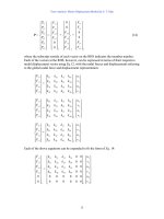
In matrix form these two equations become one matrix equation:
⎥
⎦
⎤
⎢
⎣
⎡
126-
6-8
⎭
⎬
⎫
⎩
⎨
⎧
ab
b
φ
θ
EK
EK
=
⎭
⎬
⎫
⎩
⎨
⎧
40
0
To obtain the above form, we have reversed the sign for all expressions in the second
equilibrium equation so that the matrix at the LHS is symmetric. The solution is:
EK
θ
b
= 4 kN-m
EK
φ
ab
= 5.33 kN-m
Substituting back to the moment-rotation formulas, we obtain
M
ba
= −16 kN-m
M
ab
= −24 kN-m
M
bc
= 16 kN-m
For the member-end moment not appearing in the two equilibrium equations, M
cb
, we
obtain
M
cb
= (2EK)
bc
θ
b
+(4EK)
bc
θ
c
− (6EK)
φ
bc
+ M
F
bc
= (2EK)
bc
θ
b
= 2EK
θ
b
= 8 kN-m
We can now draw the moment diagram, and a new deflection diagram, which is refined
from the rough sketch done at the beginning of the solution process, using the
information contained in the moment diagram.
Beam and Frame Analysis: Displacement Method, Part II by S. T. Mau
221
Moment and deflection diagrams.
Example 14. Find all the member-end moments of the frame shown. EI is constant for
all members.
A frame with an inclined member.
Solution. There is clearly one nodal rotation unknown,
θ
b
, and one nodal translation
unknown,
∆
. The presence of an inclined member, however, complicates the geometric
relationship between nodal translation and member rotation. We shall, therefore, deal
with the geometric relationship first.
Details of nodal displacement relationship.
10 kN
4 m
4 m
a
b
c
a
b
c
∆
∆
3 m
b
∆
∆
1
∆
2
b'
b"
a
−24 kN-m
−8 kN-m
16 kN-m
I
nflection point
Beam and Frame Analysis: Displacement Method, Part II by S. T. Mau
222
Because the member lengths are not to change, the post-deformation new location of
node b is at b’, the intersection of a line perpendicular to member ab and a line
perpendicular to member bc. Member rotations of member ab and member bc are defined
by the displacements perpendicular to the member axis. They are
∆
1
for member bc and
∆
2
for member ab, respectively. From the little triangle, b-b’-b”, we obtain the following
formulas:
∆
1
=
4
3
∆
∆
2
=
4
5
∆
The rotations of member ab and member bc are defined by, respectively:
φ
ab
=
ab
L
2
∆
=
5
2
∆
φ
bc
= −
bc
L
1
∆
= −
4
1
∆
Since
∆
1
and
∆
2
are related to
∆
, so are
φ
ab
and
φ
bc
. We seek to find the relative
magnitude of the two member rotations:
φ
ab
:
φ
bc
=
5
2
∆
: (−
4
1
∆
) = (
5
1
)(
4
5
∆
) : (−
4
1
) (
4
3
∆
) = (
4
1
∆
) : (−
16
3
∆
) =1 : (−
4
3
)
Consequently,
φ
bc
= (−
4
3
)
φ
ab
We shall designate
φ
ab
as the member rotation unknown and express
φ
bc
in terms of
φ
ab
.
Together with the nodal rotation unkown
θ
b
, we have two DOFs,
θ
b
and
φ
ab
. We seek to
write two eqilibrium equations.
The first equilibrium equation comes from the nodal moment equilibrium at node b:
Σ M
b
= 0 M
ba
+ M
bc
= 0 (16)
The second comes from the moment equilibrium of the whole structure about a point “o”:
Σ M
o
= 0 10(4)(
3
4
)
+ V
a
[5+4(
3
5
)] + M
ab
+ M
cb
= 0 (17)
Beam and Frame Analysis: Displacement Method, Part II by S. T. Mau
223
FBDs of the whole structure and the inclined member.
Note that it is necessary to select the intersection point, “o”, for the moment equation so
that no axial forces are included in the equation. From the FBD of the inclined member,
we obtain
V
a
= −
5
1
(M
ab
+ M
ba
)
Substituting the above formula into Eq. 17, it becomes
−4M
ab
− 7M
ba
+ 3M
cb
= 160 (17)
There are four moment unknowns, M
ab
, M
ba
, M
bc
and M
cb
in two equations. We now
establish the moment-rotation (M-
θ
-
φ
) formulas, noting that
φ
bc
is expressed in terms of
φ
ab
and
EK
ab
: EK
bc
=
5
1
EI :
4
1
EI =
1:
1.25
We can designate EK for EK
ab
and express EK
bc
in EK as well:
EK
ab
= EK
EK
bc
= 1.25 EK
10 kN
a
b
c
V
a
M
ab
R
a
R
c
a
V
a
M
ab
R
a
V
b
M
ba
T
b
5 m
o
3
4
4 m
M
cb
b
Beam and Frame Analysis: Displacement Method, Part II by S. T. Mau
224
After successive substitution, the moment-rotation formulas are:
M
ba
= (4EK)
ab
θ
b
+(2EK)
ab
θ
a
−(6EK)
ab
φ
ab
+
M
F
ba
= (4EK)
ab
θ
b
−(6EK)
ab
φ
ab
= 4EK
θ
b
−6EK
φ
ab
M
ab
= (4EK)
ab
θ
a
+(2EK)
ab
θ
b
−(6EK)
ab
φ
ab
+ M
F
ab
= (2EK)
ab
θ
b
−(6EK)
ab
φ
ab
= 2EK
θ
b
− 6EK
φ
ab
M
bc
= (4EK)
bc
θ
b
+ (2EK)
bc
θ
c
−(6EK)
bc
φ
bc
+ M
F
bc
= (4EK)
bc
θ
b
−(6EK)
bc
φ
bc
= 5EK
θ
b
+ 5.625EK
φ
ab
M
cb
= (4EK)
bc
θ
c
+ (2EK)
bc
θ
b
−(6EK)
bc
φ
bc
+ M
F
cb
= (2EK)
bc
θ
b
−(6EK)
bc
φ
bc
= 2.5EK
θ
b
+ 5.625EK
φ
ab
Substituting the moment expressions above into Eq. 16 and Eq. 17, we obtain the
following two equations in
θ
b
and
φ
ab
.
9EK
θ
b
– 0.375EK
φ
ab
=0
−28.5EK
θ
b
+82.875EK
φ
ab
= 160
Multiplying the first equation by 8 and the second equation by (1/9.5), we obtain
72EK
θ
b
– 3EK
φ
ab
= 0
−3EK
θ
b
+ 8.723EK
φ
ab
=16.84
In matrix form, we have
⎥
⎦
⎤
⎢
⎣
⎡
−
−
8,7233
372
⎭
⎬
⎫
⎩
⎨
⎧
ab
b
φ
θ
EK
EK
=
⎭
⎬
⎫
⎩
⎨
⎧
84.16
0
The solution is
Beam and Frame Analysis: Displacement Method, Part II by S. T. Mau
225
EK
θ
b
= 0.0816 kN-m
EK
φ
ab
= 1.959 kN-m
Substituting back to the moment-rotation formulas, we obtain the member-end moments:
M
ba
= −11.43 kN-m
M
ab
= −11.59 kN-m
M
bc
= 11.43 kN-m
M
cb
= 11.22 kN-m
From the member-end moments we can easily obtain all the member-end shears and axial
forces as shown below.
FBDs of members ab, bc and node b.
Note the shear forces are always the first to be determined, from the member-end
moments. The axial force of member ab is then determined from the FBD of node b,
using the equilibrium equation of all vertical forces.
The moment diagram is shown below together with a new deflection diagram refined
from the initial sketch done at the beginning of the solution process, utilizing the
information presented in the moment diagram.
a
11.43 kN-m
10.52 kN
10.52 kN
11.59 kN-m
4.60 kN
4.60 kN
b
11.43 kN-m
11.22 kN-m
5.66 kN 5.66 kN
5.66 kN
4.60 kN
10 kN
10.52 kN
b
b
c
Beam and Frame Analysis: Displacement Method, Part II by S. T. Mau
226
Moment and deflection diagrams.
Example 15. Find all the member-end moments of the frame shown. EI is constant for
all members.
A frame with rotation and translation DOFs.
Solution. We observe that nodes b and c are free to rotate. Nodes b and c are also free to
translate in the horizontal direction by the same amount. As a result of this translation of
both node b and node c, member ab and member cd have member rotations, but not
member bc, which has no member rotation.
2 m
2 m
2 m
4 kN
a
b
c
d
a
b
c
d
∆
∆
a
b
11.43 kN-m
−11.22 kN-m
−11.59 kN-m
I
nflection point
Beam and Frame Analysis: Displacement Method, Part II by S. T. Mau
227
Sketch of the deflection of the frame.
The two member rotations are related to the single translation,
∆
, and we can find the
relative magnitude of the two easily.
φ
ab
:
φ
cd
=
ab
L
∆
:
cd
L
∆
=
4
∆
:
2
∆
= 1 : 2
Thus,
φ
cd
= 2
φ
ab
In sum, there are three degrees of freedom:
θ
b,
θ
c
and
φ
ab
. We need three equations of
equilibrium:
The first equilibrium equation comes from the nodal moment equilibrium at node b:
Σ M
b
= 0 M
ba
+ M
bc
= 0
The second comes from the nodal moment equilibrium at node c:
Σ M
c
= 0 M
cb
+ M
cd
= 0
The third comes from the horizontal force equilibrium of the whole structure:
Σ F
x
= 0 V
a
+ V
d
= 4
FBD of the whole structure.
The two shear forces in the third equation can be expressed in terms of member-end
moments, via the FBD of each member.
V
a
= −
4
1
(M
ab
+ M
ba
) + 2
4 kN
a
b
c
d
M
ab
V
a
R
a
M
dc
V
d
R
d
Beam and Frame Analysis: Displacement Method, Part II by S. T. Mau
228
V
d
= −
2
1
(M
dc
+ M
cd
)
FBDs of the two column members of the rigid frame
By virtue of the shear-moment relationship, the third equation becomes:
V
a
+ V
d
= 4 −M
ab
− M
ba
− 2M
dc
− 2M
cd
= 8
There are six moment unknowns in the three equilibrium equations. We now express the
member-end moments in terms of the three displacement unknowns,
θ
b,
θ
c
and
φ
ab
.
Note that we can designate a common stiffness factor EK for all three members:
EK
ab
= EK, EK
bc
= 2EK, EK
cd
= 2EK
Noting
φ
cd
= 2
φ
ab
, we can simplify the moment-rotation expresses as shown below.
M
ba
= (4EK)
ab
θ
b
+(2EK)
ab
θ
a
−(6EK)
ab
φ
ab
+
M
F
ba
= (4EK)
ab
θ
b
−(6EK)
ab
φ
ab
+ M
F
ba
= 4EK
θ
b
− 6EK
φ
ab
+ 2
M
ab
= (4EK)
ab
θ
a
+(2EK)
ab
θ
b
−(6EK)
ab
φ
ab
+ M
F
ab
= (2EK)
ab
θ
b
− (6EK)
ab
φ
ab
+ M
F
ab
= 2EK
θ
b
− 6EK
φ
ab
−2
M
bc
= (4EK)
bc
θ
b
+(2EK)
bc
θ
c
− (6EK)
bc
φ
bc
+ M
F
bc
V
b
M
ba
4 kN
2 m
2 m
V
a
M
ab
c
d
M
dc
V
d
M
cd
V
c
b
a
2 m
Beam and Frame Analysis: Displacement Method, Part II by S. T. Mau
229
= (4EK)
bc
θ
b
+(2EK)
bc
θ
c
= 8EK
θ
b
+ 4EK
θ
c
M
cb
= (2EK)
bc
θ
b
+(4EK)
bc
θ
c
-(6EK)
bc
φ
bc
+ M
F
cb
= (2EK)
bc
θ
b
+(4EK)
bc
θ
c
= 4EK
θ
b
+ 8EK
θ
c
M
cd
= (4EK)
cd
θ
c
+(2EK)
cd
θ
d
-(6EK)
φ
cd
+
M
F
cd
= (4EK)
cd
θ
c
−(6EK)
cd
φ
cd
+ M
F
cd
= 8EK
θ
c
−24EK
φ
ab
M
dc
= (4EK)
cd
θ
d
+(2EK)
cd
θ
c
−(6EK)
cd
φ
cd
+ M
F
dc
= (2EK)
cd
θ
c
−(6EK)
cd
φ
cd
= 4EK
θ
c
− 12EK
φ
ab
Substituting all the moment-rotation formulas into the three equilibrium equations, we
obtain the following three equations for three unknowns.
12EK
θ
b
+ 4EK
θ
c
−6EK
φ
ab
= -2
4 EK
θ
b
+16EK
θ
c
−24EK
φ
ab
= 0
−6 EK
θ
b
− 24EK
θ
c
+84EK
φ
ab
= 8
The matrix form of the above equation reveals the expected symmetry in the square
matrix at the LHS:
⎥
⎥
⎥
⎦
⎤
⎢
⎢
⎢
⎣
⎡
−−
−
−
84246
24164
6412
⎪
⎭
⎪
⎬
⎫
⎪
⎩
⎪
⎨
⎧
ab
b
EK
EK
EK
φ
θ
θ
c
=
⎪
⎭
⎪
⎬
⎫
⎪
⎩
⎪
⎨
⎧
−
8
0
2
The solution is
EK
θ
b
= −2/11 kN-m
EK
θ
c
= 13/44 kN-m
Beam and Frame Analysis: Displacement Method, Part II by S. T. Mau
230
EK
φ
ab
= 1/6 kN-m
Substituting back, we obtain, for the member-end moments:
M
ba
= 3/11 kN-m = 0.27 kN-m
M
ab
= −37/11 kN-m = −3.36 kN-m
M
bc
= −3/11 kN-m = −0.27 kN-m
M
cb
= −18/11 kN-m = 1.64 kN-m
M
cd
= −18/11 kN-m = −1.64 kN-m
M
dc
= −9/11 kN-m = −0.82 kN-m
From the member-end moments, the shear forces at member ends are computed from the
FBD of each member. The axial forces are obtained from the nodal force equilibrium.
FBDs of each member and nodes b and c( force only).
The moment diagram and a refined deflection diagram are shown below.
4 kN
a
b
c
d
2.77 kN
3.36 kN-m
1.23 kN
0.27 kN-m
0.27 kN-m
1.64 kN-m
0.69 kN
0.69 kN
c
b
1.64 kN-m
0.82 kN-m
1.23 kN
1.23 kN
1.23 kN
0.69 kN
0.69 kN
0.69 kN
0.69 kN
0.69 kN
1.23 kN
c
1.23 kN
1.23 kN
0.69 kN
b
1.23 kN
1.23 kN
Beam and Frame Analysis: Displacement Method, Part II by S. T. Mau
231
Moment and deflection diagrams.
a
b
c
d
a
b
c
d
3.36 kN-m
-0.27 kN-m
2.18 kN-m
-1.64 kN-m
0.82 kN-m
I
nflection point
Beam and Frame Analysis: Displacement Method, Part II by S. T. Mau
232
Problem 2. Use the slope-deflection method to find all the member-end moments of the
beams and frames shown and draw the moment and deflection diagrams.
(1) (2)
(3) (4)
(5) (6)
Problem 2.
2 m
2 m
3 m
a
c
b
3 kN/m
4 kN
2EI
E
I
2 m
2 m
3 m
a
cb
8 kN
2EI
E
I
2 kN-m
50 kN
a
b
c
4 m 4 m
4 m
8 m
E
I
2EI2EI
50 kN
ab
c
4 m 4 m
4 m
8 m
E
I
2EI2EI
2 m
2 m
2 m
4 kN
a
b
c
2 m
2 m
2 m
4 kN
a
b
c
E
I
E
I
E
I
E
I
d
d
Beam and Frame Analysis: Displacement Method, Part II by S. T. Mau
233
4. Matrix Stiffness Analysis of Frames
Overview. The slope-deflection method was developed for hand-calculation. In order to
minimize the number of nodal rotation and member rotation unknowns, the axial
deformation of each member is neglected. As a result, the member rotations are often
inter-related. As we have observed in the example problems, if we encounter an inclined
member, the formulas for the geometric relations can be very involved. On the other
hand, if we allow the axial deformation to be included in the displacement calculation,
then the nodal displacements at one node are completely independent from those at the
other end of a member and we will have three nodal unknowns at each node: two
translation unknowns and one rotation unknown. Although the number of unknowns for a
given frame will be more than that in a slope-deflection formulation, the formulation
process becomes much more straightforward. The formulation presented herein parallels
to that for truss analyses.
Consider the rigid frame problem shown below. We treat this problem as one with two
members and three nodes
A rigid frame problem.
We shall convert the above problem into the superposition of two problems: one with
member ab locked at both ends and the other with external forces and moments applied
only at nodal points. The first problem can be solved at the level of a single member.
Indeed the member-end moments are tabulated in the fixed-end moment table. The
member-end shear forces can then be computed from the FBD of the member. The
member-end moments and forces in the first problem, when reversed in signs, become
the nodal moments and forces of the second problem, which has applied moments and
forces only at the nodes. We shall henceforth concentrate on the second problem, with
external forces/moments applied only at nodal points.
2 m
2 m
2 m
4 kN
a
b
c
Beam and Frame Analysis: Displacement Method, Part II by S. T. Mau
234
Superposition of two problems.
The moment and force applied at support a are taken up by the support directly. They
should be included in the calculation of forces acting on the support, but be excluded in
the forces acting on the nodes of the frame. The problem is reduced to the one shown in
the left part of the figure below. The right part of the figure includes a global coordinate
system, which is necessary because each member is oriented in different directions and
we need a common coordinate system to relate member displacements and forces to those
of other members. We also replace the alphabetic system by the numeric system for
naming nodes because the latter is easier to program for computer solutions.
Frames with loads applied only at nodes.
In the matrix displacment formulation, it is easier to begin without applying the
displacement and force conditions first. Only when the global displacement-force
equations are forumulated, can we then impose the displacement and force conditions im
preparation for a numerical solution. Thus, the next step is to define the nodal
a
b
c
4 kN
a
b
2 kN
2 kN
2 kN-m
2 kN
2 kN
2 kN-m
2 kN-m
+
a
b
c
2 kN
2 kN-m
1
2
3
2 kN
2 kN-m
x
y
2 kN-m