Handbook Of Shaft Alignment Episode 1 Part 7 doc
Bạn đang xem bản rút gọn của tài liệu. Xem và tải ngay bản đầy đủ của tài liệu tại đây (916.21 KB, 30 trang )
Disadvantages:
.
Requires lubrication
.
Temperature limitation due to lubricant
.
Difficult to calculate reaction forces and moments of turbomachinery rotors when using
these couplings since the values for the coefficient of friction between the gear teeth vary
considerably
Coupling hubs and sleeves on shafts
Coupling hubs and sleeves on spool
FIGURE 4.8 Two different variations of gear couplings employing a spool piece.
Sleeve
Gear tooth in
“pivoted” position
Gear tooth in
“tilted” position
Centerline of
sleeve
Centerline of coupling
hub (with gear teeth)
FIGURE 4.9 Tilted and pivoted positions of the gear teeth in its sleeve.
Piotrowski / Shaft Alignment Handbook, Third Edition DK4322_C004 Final Proof page 150 6.10.2006 5:43pm
150 Shaft Alignment Handbook, Third Edition
4.4.1.3 Metal Ribbon Couplings
The metal ribbon coupling was introduced around 1919 by Bibby Co. Metal ribbon couplings
consist of two hubs with axial ‘‘grooves’’ on the outer diameter of the hub where a continuous
S-shaped grid meshes into the grooves. Misalignment and axial movement is achieved by
flexing and sliding of the grid member in specially tapered hub ‘‘teeth.’’
.
Capacity: up to 70,000 hp=100 rpm
.
Maximum recommended speed: to 6000 rpm
.
Shaft bores: to 20 in.
.
Shaft spacing: to 12 in.
Tilted position
Pivoted position
Pivoted position
Tilted position
Pivoted position
FIGURE 4.10 Gear tooth tracking pattern when subjected to misalignment conditions.
Piotrowski / Shaft Alignment Handbook, Third Edition DK4322_C004 Final Proof page 151 6.10.2006 5:43pm
Flexible and Rigid Couplings 151
.
Special designs and considerations: Grid fabricated from hardened, high-strength steel.
Close coupled hubs with removable spacer available.
Advantages:
.
Easy to assemble and disassemble
.
Long history of successful applications
.
Torsionally soft
Disadvantages:
.
Requires lubrication
.
Temperature limited
.
Speed limited
4.4.1.4 Universal Joint Couplings
Perhaps the oldest flexible coupling in existence is the universal joint coupling. This coupling
is also known as the Cardan or Hooke joint. The basic design consists of U-shaped shaft ends
with a hole drilled through each ‘‘U’’ to accept a ‘‘þ’’ shaped cross.
If one universal joint is used to connect two shafts together, then only pure angular
misalignment can exist where the centerlines of rotation intersect at the center of the ‘‘þ’’
shaped cross. For a flexible coupling to accept both parallel and angular misalignment, there
FIGURE 4.11 Metal ribbon type coupling. (Courtesy of Falk Corporation, Milwaukee, WI. With
permission.)
Piotrowski / Shaft Alignment Handbook, Third Edition DK4322_C004 Final Proof page 152 6.10.2006 5:43pm
152 Shaft Alignment Handbook, Third Edition
must be two flexing points. Therefore most universal joint couplings have two cross=yolk
assemblies as illustrated in Figure 4.12 and Figure 4.13.
When one universal joint is used it is important to recognize that variations in angular
velocity will occur between the two connected shafts often referred to as the ‘‘Cardan error.’’
Sinusoidal motion will occur in the axial and torsional directions, producing axial vibration
and torsional (i.e., twisting) vibration particularly if the torque is transmitted and the
rotational speed is high.
When two universal joints are used it is important to recognize that sinusoidal motion will
also occur in the axial and torsional directions if the ‘‘entrance’’ and ‘‘exit’’ angles are not the
same as shown in Figure 4.13. When these angles are the same in both planes, perfect
kinematic balance exists across the coupling, canceling the torsional and thrust variance.
4.4.1.5 Flexible Link
The flexible link coupling utilizes a series of cross laced, metallic links with one end of each
link attached to a disc mounted on the driven shaft and the other end of each link attached to
a disc mounted on the driver shaft. The links are matched in pairs so that when one is in
tension, the other is in compression. Misalignment and axial displacement is accomplished by
a flexing action in the series of cross links.
FIGURE 4.12 Universal joint. (Courtesy of Zurn Industries, Erie, PA. With permission.)
a
a
a
a
w
≠ w
Correct assembly and set up
Incorrect assembly
and set up
Yoke ears not in proper
orientation on connector shaft
Angle not
the same
as other
end
With a single universal joint, if the input and output shafts are not in line, a
variation of the output shaft speed (w
) will result called Cardan error. When
two universal joints are used where the entrance and exits angles are the same
with the yokes aligned properly, the system is kinematically balanced
producing synchronous shaft rotation at the input and output ends.
FIGURE 4.13 Universal joint basics.
Piotrowski / Shaft Alignment Handbook, Third Edition DK4322_C004 Final Proof page 153 6.10.2006 5:43pm
Flexible and Rigid Couplings 153
.
Capacity: up to 1100 hp=100 rpm.
.
Maximum recommended speed: to 1800 rpm.
.
Shaft bores: up to 20 in.
.
Shaft spacing: close coupled or 100 mm spacer with certain designs.
FIGURE 4.14 Flexible link coupling. (Courtesy of Eaton Corporation, Airflex Division, Cleveland, OH
under license from Dr. Ing. Geislinger & Company, Salzburg, Austria. With permission.)
FIGURE 4.15 Leaf spring coupling. (Courtesy of Eaton Corporation, Airflex Division, Cleveland, OH.
With permission.)
Piotrowski / Shaft Alignment Handbook, Third Edition DK4322_C004 Final Proof page 154 6.10.2006 5:43pm
154 Shaft Alignment Handbook, Third Edition
.
Special designs and considerations: An axial ‘‘fixation’’ device can be installed to prevent
any axial movement if desired. Different designs can accommodate unidirectional or
bidirectional rotation.
Advantages:
.
No lubrication required
Disadvantages:
.
Limited axial movement
.
Limited misalignment capabilities (can accept pure angular misalignment only)
4.4.1.6 Leaf Spring
This coupling employs a series of radially positioned sets of leaf springs attached to an outer
drive member and indexed into axial grooves in the inner drive member. The chamber around
each spring set is filled with oil. When the spring pack is deflected, damping occurs as the oil
flows from one side of the spring pack to the other.
.
Capacity: up to 15,000 hp=100 rpm
.
Maximum recommended speed: 3600 rpm
.
Shaft bores: up to 12 in.
.
Shaft spacing: up to 40 in.
.
Special designs and considerations: Designed primarily for diesel and reciprocating
machines. Capable of transmitting shock torque values substantially higher than other
couplings until springs reach their maximum allowable angular movement where the
radial stiffness increases substantially. Various spring stiffnesses can be installed in each
size coupling to properly match the torsional requirements to the drive system.
Advantages:
.
Torsionally soft with good damping characteristics
.
Freedom of axial shaft movement
FIGURE 4.16 Pin drive type coupling. (Courtesy of David Brown Gear Industries, Agincourt, Ontario,
Canada. With permission.)
Piotrowski / Shaft Alignment Handbook, Third Edition DK4322_C004 Final Proof page 155 6.10.2006 5:43pm
Flexible and Rigid Couplings 155
Disadvantages:
.
Requires lubricant for damping
.
Temperature limitations due to lubricant
.
Torsional characteristics change drastically with loss of oil
4.4.1.7 Pin Drive
A series of metal pins with leaf springs are placed near the outer diameter where they engage into
a series of holes bored into both shaft hubs. Some pin designs consist of a pack of flat springs with
cylindrical keepers at each end that act as the flexing element in the coupling design. The spring
sets can swivel in the pin connection to allow movement across the width of the spring set.
.
Capacity: up to 3800 hp at 100 rpm
.
Maximum recommended speed: to 4000 rpm
.
Shaft bores: to 13 in.
.
Shaft spacing: close coupled (1=8to1=2 in.).
.
Special designs and considerations: Drive pins can be fabricated to accommodate various
torsional flexibility requirements and are indexed into oil impregnated bronze bushings in
the coupling hubs.
Advantages:
.
Can accommodate up to 1=2 in. of axial displacement
.
No lubrication required
Disadvantages:
.
Limited offset misalignment capability
4.4.1.8 Elastomeric Couplings
A wide variety of design variations that employ an elastomeric medium to transmit torque
and accommodate misalignment as illustrated in Figure 4.17. Most of these couplings are
torsionally ‘‘soft’’ to absorb high starting torques or shock loads.
.
Capacity: up to 67,000 hp=100 rpm but varies widely with design
.
Maximum recommended speed: approximately 5000 rpm (varies widely with design)
.
Shaft bores: up to 30 in.
.
Shaft spacing: up to 100 in. (varies widely)
.
Special designs and considerations: A considerable amount of inventiveness and ingenuity
has been applied to this type of coupling design through the years as evidenced by the large
array of design variations. The elastomeric medium is generally natural or synthetic
rubber, urethane, nylon, teflon, or oil-impregnated bronze. As the elastomer is markedly
softer than the hubs and solid-driving elements (wedges, pins, jaws, etc.), wear is minimal
and replacement of the elastomer itself is all that is usually needed for periodic servicing.
Advantages:
.
Minimal wear in coupling
.
Acts as vibration damper and isolator
Piotrowski / Shaft Alignment Handbook, Third Edition DK4322_C004 Final Proof page 156 6.10.2006 5:43pm
156 Shaft Alignment Handbook, Third Edition
FIGURE 4.17 Elastomeric couplings. [Courtesy of (a and b) Lovejoy Corporation, Downers Grove, IL;
(c) Holset Engineering Company, Cincinnati, OH; (d) T.B. Wood’s Sons, Chambersburg, PA.
With permission.]
(continued )
Piotrowski / Shaft Alignment Handbook, Third Edition DK4322_C004 Final Proof page 157 6.10.2006 5:44pm
Flexible and Rigid Couplings 157
FIGURE 4.17 (continued)
FIGURE 4.18 Contoured diaphragm coupling: (a) cutaway view of the flexible disk at one end of the
coupling; (b) entire coupling. (Courtesy of Kopflex Corporation, Baltimore, MD. With permission.)
Piotrowski / Shaft Alignment Handbook, Third Edition DK4322_C004 Final Proof page 158 6.10.2006 5:44pm
158 Shaft Alignment Handbook, Third Edition
.
Acts as electrical shaft current insulator in some designs
.
Torsionally ‘‘soft’’
.
Accepts some axial movement and dampens axial vibration
.
No lubrication required
Disadvantages:
.
Speed limited due to distortion of elastomer from high centrifugal forces, causing imbal-
ance
.
Deterioration of elastomer from temperature, oxidation of rubber, corrosive attack from
undesirable environment
.
Potential safety hazard if elastomeric member releases from drive elements
.
Some designs may cause undesirable axial forces
.
Heat generated from cyclic flexing of elastomer
4.4.2 METALLIC MEMBRANE=DISK-TYPE COUPLING DESIGNS
4.4.2.1 Diaphragm Couplings
Transmission of power occurs through two flexible metal diaphragms, each bolted to the
outer rim of the shaft hubs and connected via a spacer tube. Misalignment and axial
displacement is accomplished by flexing of the diaphragm members.
.
Capacity: up to 30,000 hp
.
Maximum recommended speed: up to 30,000 rpm
.
Shaft bores: up to 7 in.
.
Shaft spacing: 2 to 200 in.
.
Special designs and considerations: Metal diaphragm couplings are a highly reliable
drive component when operated within their rated conditions. Exceeding the maximum
allowable angular or parallel misalignment values or axial spacing will eventually
result in disc failure. As the diaphragm is, in effect a spring, considerations must be
given to the axial spring rate and vibration characteristics to insure that the diaphragm
coupling natural frequency does not match rotating speeds or harmonics in the drive
system.
Advantages:
.
Excellent balance characteristics
.
No lubrication required
.
Low coupling weight and bending forces on shafts when operated within alignment limits
.
Accepts high temperature environment
Disadvantages:
.
Limited axial displacement and oscillation
.
Proper shaft spacing requirements are generally more stringent than other coupling types
.
Excessive misalignment will transmit high loads to shafting
Piotrowski / Shaft Alignment Handbook, Third Edition DK4322_C004 Final Proof page 159 6.10.2006 5:44pm
Flexible and Rigid Couplings 159
OD bolts
Spacer bolts
Diaphragm pack
Rigid hub
Shipping
screw
Spacer
(a)
Bolted Connections
FIGURE 4.19 Flexible disk couplings. [Courtesy of (a) Zurn Industries, Erie, PA; (b) Thomas-Rexnord,
Warren, PA; (c) Schmidt Couplings, Cincinnati, OH. With permission.]
Piotrowski / Shaft Alignment Handbook, Third Edition DK4322_C004 Final Proof page 160 6.10.2006 5:44pm
160 Shaft Alignment Handbook, Third Edition
4.4.2.2 Flexible Disc Couplings
The flexible disc coupling is very similar in design principles to the diaphragm coupling with
the exception that multiple, thinner discs or a noncircular flexing member is used as the
flexing element instead of circular, contoured diaphragm elements.
FIGURE 4.20 Rigid coupling. (Courtesy of Browning Mfg., Maysville, KY. With permission.)
FIGURE 4.21 Rigid coupling on vertical pump.
Piotrowski / Shaft Alignment Handbook, Third Edition DK4322_C004 Final Proof page 161 6.10.2006 5:44pm
Flexible and Rigid Couplings 161
.
Capacity: up to 65,000 hp=100 rpm
.
Maximum recommended speed: up to 30,000 rpm
.
Shaft bores: to 12 in.
.
Shaft spacing: to 200 in.
.
Special designs and considerations: It is important to note that two disc packs (or
diaphragms) are needed to accommodate parallel misalignment whereas a single disc
can only handle pure angular misalignment. Convolutions in the discs provide a linear
stiffness vs. deflection characteristics as opposed to flat disc profiles. Once again, coup-
ling axial resonance information must be known to prevent problems where a match may
occur with machinery running speeds, higher order harmonics, or subsynchronous for-
cing mechanisms (oil whirl, looseness of bearing housings, clearance induced whirls, etc.).
Advantages and disadvantages:
.
Same as diaphragm couplings
4.5 RIGID COUPLING DESIGN
Well before flexible couplings came into existence, rigid couplings were used to connect two
(or more) shafts together. Although flexible couplings are used on the vast majority of
rotating machinery drive systems today, rigid couplings still have their place and are fre-
quently used on systems where very little misalignment occurs and in situations, where high
horsepowers are transmitted from shaft to shaft, or in vertical pump applications where one
of the drive motor bearings is carrying the weight (thrust) of the armature and pump rotors.
It is important to recognize that when two shafts are connected together with rigid
couplings, the two separate shafts have effectively become one continuous shaft. Therefore
the ‘‘misalignment’’ tolerances for rigid couplings are the same tolerances that apply for
acceptable runout conditions on a single shaft as discussed in Chapter 6. There are two classic
rigid coupling alignment techniques—the 16-point and 20-point methods and they are dis-
cussed in Chapter 7 but other techniques have also been successfully employed on rigid
couplings. It is highly recommended that rigid couplings be disconnected when taking
alignment measurements between the two shafts as explained in Chapter 1 and Chapter 2.
4.6 FLEXIBLE COUPLING LUBRICATION
The majority of mechanically flexible couplings require lubrication. There are basically two
methods used to lubricate couplings: single charge or continuous feed. Greases are generally
used in single charge lubricated couplings and the type is generally specified by the coupling
manufacturer.
Problems that can occur in greased packed couplings are:
1. Loss of lubricant from leakage at: lube seals, shaft keyways, mating flange faces, or
lubricant filler plugs.
2. Excessive heat generated in the coupling from an insufficient amount of lubricant,
excessive misalignment, or poor heat dissipation inside the coupling shroud, which
reduces viscosity and accelerates oxidation.
3. Improper lubricant.
4. The centrifugal forces generated in the coupling can be high enough to separate greases
into oils and soaps.
Piotrowski / Shaft Alignment Handbook, Third Edition DK4322_C004 Final Proof page 162 6.10.2006 5:44pm
162 Shaft Alignment Handbook, Third Edition
As soaps have a higher specific gravity than oil, it will eventually collect where the force is
the highest (namely where the gear teeth are located), causing a buildup of sludge.
Periodically inspect the inside of the coupling guard and directly under the coupling to see if
any leakage is occurring. If so, do not continue to add more grease because the oil usually
leaks out and the soaps continue to build up. Thoroughly clean the coupling, replace the seals
and gaskets, and replenish with the correct kind and amount of lubricant, preferably a
‘‘coupling grease’’ in which the oil and soap have the same specific gravity so they do not
separate under centrifugal force.
Continuous feed lubrication systems generally use the same lube oil as the bearings
and spray tubes are positioned to inject a directed stream of oil into the coupling as shown
in Figure 4.22.
In addition to supplying lubricant to the coupling, a continuous supply of oil acts as an
excellent heat transfer agent, maintaining a relatively stable temperature in the coupling.
However contaminants in the oil, particularly water (which often condenses in lube oil tanks)
or corrosive process gases carried over from the inboard oil seals on compressors, can damage
the coupling in time. Stainless steel lube oil piping, condensate and particulate matter removal
with lube oil centrifuges, 5–10 mm filters, and entrained gas venting systems will alleviate
many of these problems.
4.7 COUPLING INSTALLATION
Once a flexible coupling has been selected for a specific service, the next important step is
proper installation. It is quite easy to destroy an expensive coupling assembly in short order
due to sloppy shaft fits, incorrect key dimensions, improperly measured shaft diameters,
storage in a corrosive environment, and so on. After the coupling has been uncrated, the
following steps should be performed before installation is even attempted.
1. Insure that the correct type of coupling was ordered and all the parts are with it (bolts,
spacer spool, hubs, cover, gaskets, etc.). Clean any and all protective coatings from the
surfaces. Thoroughly inspect each component for damage.
2. Physically measure all the dimensions against the coupling drawing and parts
listings paying particular attention to coupling hub bores, keyway dimensions, and
spool length.
Oil return
Coupling sleeve
Coupling hub
Oil spray tube
Shaft
FIGURE 4.22 Continuous oil feed systems for a gear coupling.
Piotrowski / Shaft Alignment Handbook, Third Edition DK4322_C004 Final Proof page 163 6.10.2006 5:44pm
Flexible and Rigid Couplings 163
3. Measure the shafts where the coupling is going to be installed. Measure the outside
diameters of each shaft, the keyway widths and depths, and the distance between the
shafts, insuring that each shaft has been placed in its normal axial position during
operation as shown in Figure 4.24 through Figure 4.26.
4. If possible, assemble the entire coupling before it is placed on the shaft checking
for proper gear tooth clearances, elastomeric member fits, bolt hole diameter fits,
and clearances.
4.8 COUPLING HUB ATTACHMENT METHODS
There are a variety of methods employed to attach the coupling hubs to a shaft, each one
having its advantages and disadvantages. Recommended guidelines for installing these vari-
ous shafts to coupling hub fits are outlined ahead and should be followed to insure a proper
fit to prevent slippage or unwanted shaft fretting. Shaft fretting occurs when a coupling hub is
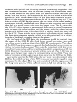
FIGURE 4.23 Pitting across entire surface of gear teeth from operating with no lubricant.
Piotrowski / Shaft Alignment Handbook, Third Edition DK4322_C004 Final Proof page 164 6.10.2006 5:44pm
164 Shaft Alignment Handbook, Third Edition
loose on its shaft and the oscillatory rocking motions of the hub cause pitting on the mating
surfaces of the shaft and the coupling hub.
Coupling hub to shaft fits are classified as follows:
.
Straight bore, sliding clearance with keyways
.
Straight bore, interference fit with keyways
.
Splined shaft with end lock nut
.
Tapered bore, interference fit with keyways
.
Keyless taper bore
.
Locking taper cone
4.9 KEYS AND KEYWAYS
A large percentage of shafts employ one or more keys to prevent the coupling hub from
rotating on the shaft as the rotational force is applied. The American National Standards
FIGURE 4.24 Measuring bore of coupling hub with a snap gauge.
FIGURE 4.25 Using an outside micrometer to measure the snap gauge.
Piotrowski / Shaft Alignment Handbook, Third Edition DK4322_C004 Final Proof page 165 6.10.2006 5:44pm
Flexible and Rigid Couplings 165
Institute (ANSI) has set up design guidelines for proper shaft sizes to key sizes and these are
shown in Table 4.1.
4.9.1 TYPES OF KEYS
There are three different classes of key fits:
.
Class 1—side and top clearance, relatively loose fit, only applies to parallel keys (see
Table 4.2)
FIGURE 4.26 Using an inside micrometer to measure the distance between the shaft ends.
TABLE 4.1
Key and Keyway Sizes for Various Shaft Diameters
Over
0.31250
0.43750
0.56250
0.87500
1.25000
1.37500
1.75000
2.25000
2.75000
3.25000
3.75000
4.50000
5.50000
6.50000
7.50000
9.00000
To (inclusive)
0.43750
0.56250
0.87500
1.25000
1.37500
1.75000
2.25000
2.75000
3.25000
3.75000
4.50000
5.50000
6.50000
7.50000
9.00000
11.00000
Width (W)
0.09375
0.12500
0.18750
0.25000
0.31250
0.37500
0.50000
0.62500
0.75000
0.87500
1.00000
1.25000
1.50000
1.75000
2.00000
2.50000
Square
0.09375
0.12500
0.18750
0.25000
0.31250
0.37500
0.50000
0.62500
0.75000
0.87500
1.00000
1.25000
1.50000
1.75000
2.00000
2.50000
Rectangular
—
0.09375
0.12500
0.18750
0.25000
0.25000
0.37500
0.43750
0.50000
0.62500
0.75000
0.87500
1.00000
1.50000
1.50000
1.75000
Square
0.04688
0.06250
0.09375
0.12500
0.15625
0.18750
0.25000
0.31250
0.37500
0.43750
0.50000
0.62500
0.75000
0.87500
1.00000
1.25000
Rectangular
—
0.04688
0.06250
0.09375
0.12500
0.12500
0.18750
0.21875
0.25000
0.31250
0.37500
0.43750
0.50000
0.75000
0.75000
0.87500
Nominal Shaft
Diameter
Nominal Key Size
Height (H)
Nominal Keyseat
Depth (H/2)
All dimensions are given in inches. Square keys preferred for shaft dimensions above line rectangular
keys below.
Source : Machinery's Handbook, 21st ed., Industrial Press, New York, NY, 1980.
Piotrowski / Shaft Alignment Handbook, Third Edition DK4322_C004 Final Proof page 166 6.10.2006 5:44pm
166 Shaft Alignment Handbook, Third Edition
.
Class 2—minimum to possible interference, relatively tight fit
.
Class 3—interference with degree of interference not standardized
Shafts with two keyways can present another type of problem from improper machining of
the coupling hub or shaft keyways as illustrated in Figure 4.28. If the offset gap is larger than
10% of the total key width, it is recommended that the shaft or coupling hub be reworked for
improved indexing of the keys in their mating keyways.
TABLE 4.2
Key Fits
+0
−2
+0
−2
+0
−3
+0
−3
+0
−4
+0
−6
+2
−0
+3
−0
+3
−0
+4
−0
+4
−0
+4
−0
4 CL
0
5 CL
0
6 CL
0
7 CL
0
8 CL
0
10 CL
0
+0
−2
+0
−2
+0
−3
+0
−3
+0
−4
+0
−6
+0
−15
+0
−15
+0
−15
+0
−15
+0
−15
+0
−15
+10
−0
+10
−0
+10
−0
+10
−0
+10
−0
+10
−
0
32 CL
5 CL
32 CL
5 CL
33 CL
5 CL
33 CL
5 CL
34 CL
5 CL
34 CL
5 CL
+0
−3
+0
−3
+0
−4
+0
−4
+0
−5
+0
−6
+0
−8
+0
−13
+2
−0
+3
−0
+3
−0
+4
−0
+4
−0
+4
−0
+4
−0
+4
−0
5 CL
0
6 CL
0
7 CL
0
8 CL
0
9 CL
0
10 CL
0
12 CL
0
17 CL
0
+0
−3
+0
−3
+0
−4
+0
−4
+0
−5
+0
−6
+0
−8
+0
−13
+0
−15
+0
−15
+0
−15
+0
−15
+0
−15
+0
−15
+0
−15
+0
−15
+10
−0
+10
−0
+10
−0
+10
−0
+10
−0
+10
−0
+10
−0
+10
−0
33 CL
5 CL
33 CL
5 CL
34 CL
5 CL
34 CL
5 CL
35 CL
5 CL
36 CL
5 CL
38 CL
5 CL
43 CL
5 CL
0.500
0.750
1.000
1.500
2.500
3.500
0.500
0.750
1.000
1.500
2.500
0.500
0.750
1.000
1.500
3.000
4.000
6.000
7.000
0.500
0.750
1.000
1.500
3.000
4.000
6.000
Type of Key square
Type of Key rectangular
Key Width
Side Fit Top and Bottom Fit
Fit
Range KeyKey
Shaft
Keyseat
Hub
KeyseatOver
To
(inclusive)
Fit
Range
Depth ToleranceWidth Tolerance
Keyseat
Ke
y
dimensions are in inches. Fit dimensions are in mils (1 mil = 0.001in.)
—
—
Piotrowski / Shaft Alignment Handbook, Third Edition DK4322_C004 Final Proof page 167 6.10.2006 5:44pm
Flexible and Rigid Couplings 167
4.9.2 STRAIGHT BORE—SLIDING CLEARANCE WITH KEYWAYS
This method of shaft and coupling hub fit is used extensively in the industry and provides the
easiest and the quickest installation of the coupling hub. However shaft fretting is likely to
occur with this sort of arrangement due to the clearance between the coupling hub and the
shaft. The best arrangement is to have a light press fit (i.e., 0 to 1 mil of clearance). To prevent
the coupling hub from sliding axially along the shaft, set screws are usually locked against the
key as shown in Figure 4.29. A light press fit often requires that the coupling hub be heated
slightly (around 2008F–2508F) to thermally expand the hub to prevent from beating the hub
onto the shaft. To remove the hub, a mechanical puller is usually required. If the clearance is
excessive (e.g., 2 mils or more), when the set screw is tightened, the coupling hub is drawn off
center, causing a runout condition. Some precautions to consider when installing a straight
bore with sliding clearance coupling hub:
.
Insure clearance does not exceed 1 mil for shaft diameters up to 6 in.
.
Remove any burrs; clean components carefully before installation.
.
If hub sticks part way on, remove it and find the problem. Do not attempt to drive it on
further with a hammer.
.
Install keys before the coupling is placed on the shaft.
4.9.3 STRAIGHT BORE—INTERFERENCE FIT WITH KEYWAYS
To insure that a coupling hub can be removed once it is ‘‘shrunk’’ onto a shaft, proper
interference fits must be adhered to. The general guideline for straight bore interference fits is
found in Table 4.4.
Parallel
Gib head
Plain taper Alternate plain taper
FIGURE 4.27 Types of keys.
Improperly broached
keyway requires “offset”
FIGURE 4.28 Offset key.
Piotrowski / Shaft Alignment Handbook, Third Edition DK4322_C004 Final Proof page 168 6.10.2006 5:44pm
168 Shaft Alignment Handbook, Third Edition
The coupling is installed by heating in a clean oil bath or oven to approximately 2008F–
2508F and in some cases cooling the shaft simultaneously with a dry ice pack. Do not exceed
3008F or use any direct heat such as propane or oxyacetylene torches to expand the hub as the
material properties of the shaft can be altered by direct, high-temperature concentration.
Once the interference fit has been determined by measuring the shaft diameter and coupling
hub bores, the temperature increase needed to expand the coupling hub to exceed the shaft
diameter by 2 mils (to allow for a slide on fit) is found in Equation 4.1.
DT ¼
i
a(d À 0:002)
(4:1)
where T is the rise in coupling hub temperature from ambient (8F), i is the interference fit (in
mils), a is the coefficient of thermal expansion (in.=in. 8F), and d is the coupling hub bore
diameter (in.).
Set screw
Key
Light press fit between hub and shaft
FIGURE 4.29 Straight bore with clearance fit.
TABLE 4.3
Set Screw to Key Size Directory
Over
0.31250
0.43750
0.56250
0.87500
1.25000
1.37500
1.75000
2.25000
2.75000
3.25000
3.75000
4.50000
5.50000
To (inclusive)
0.43750
0.56250
0.87500
1.25000
1.37500
1.75000
2.25000
2.75000
3.25000
3.75000
4.50000
5.50000
6.50000
Key Width
0.09375
0.12500
0.18750
0.25000
0.31250
0.37500
0.50000
0.62500
0.75000
0.87500
1.00000
1.25000
1.50000
Set Screw Diameter
No. 10
No. 10
0.25000
0.31250
0.37500
0.37500
0.50000
0.50000
0.62500
0.75000
0.75000
0.87500
1.00000
Nominal Shaft
Diameter
All dimensions are given in inches.
Key Width–Set Screw Sizes
Piotrowski / Shaft Alignment Handbook, Third Edition DK4322_C004 Final Proof page 169 6.10.2006 5:44pm
Flexible and Rigid Couplings 169
The removal of the coupling hub is accomplished by pulling the hub off the shaft with an
acceptable puller mechanism and at times cooling the shaft with a dry ice pack. Shrink
fit coupling hubs should always have fine threaded puller holes (preferably four) in the end
of the coupling as shown in Figure 4.31.
Bearing-type pullers that ‘‘push’’ the hub off from the backside are not recommended as
there is a great possibility that the puller can twist or pitch slightly preventing a straight axial
draw on the hub. For larger shaft diameters with tight interference fits, it may be necessary to
apply gentle heating to the coupling for removal.
4.9.4 SPLINED SHAFT WITH END LOCK NUT OR LOCKING PLATE
A splined shaft and coupling arrangement is shown in Figure 4.32. There should be a slight
interference fit (0.0005 in.) to prevent backlash or rocking of the hub on the shaft.
4.9.5 TAPERED BORE—INTERFERENCE FIT WITH KEYWAYS
Tapered shaft ends are generally used where high torques and speeds are experienced on
rotating machinery, necessitating a tight coupling hub to shaft fit up. The shaft end is tapered
to provide an easier job of removing the coupling hub.
The degree of taper on a shaft end is usually expressed in terms of its slope (inches per foot).
The amount of interference fit is expressed in inches per inch of shaft diameter. The general
rule for interference fits for this type of shaft arrangement is 1 mil per inch of shaft diameter.
The distance a coupling hub must travel axially along a shaft past the point where the hub is
just touching the shaft at ambient temperatures is found in the following equation:
HT ¼
12I
ST
(4:2)
TABLE 4.4
Guidelines for Shrink Fits on Shafts
Shaft Diameter (in.) Interference Fit (in.)
1/2 to 2
2 to 6
6 and up
0.0005 to 0.0015 in.
0.005 to 0.0020 in.
0.0001 to 0.00035 inches
per inch of shaft diameter
A
B
C
D
Compare A to B and C to D
Coupling
hub
Key
Shaft
FIGURE 4.30 Measuring the shaft and coupling hub for proper fits.
Piotrowski / Shaft Alignment Handbook, Third Edition DK4322_C004 Final Proof page 170 6.10.2006 5:44pm
170 Shaft Alignment Handbook, Third Edition
where HT is the distance the coupling hub must travel to provide an interference fit equal I
(mils), I is the interference fit (mils), and ST is shaft taper (in.=ft).
The procedure for mounting a tapered coupling hub with keys:
1. Mount bracket firmly to coupling hub and slide hub onto shaft end to lightly seat the
hub against the shaft. Insure all surfaces are clean.
2. Measure hub travel gap HT with feeler gauges and lock nut down against bar. Use
Equation 3.2 to determine the correct axial travel needed to obtain the required inter-
ference fit onto the shaft.
3. Remove the coupling hub and puller assembly and place in an oven or hot, clean oil bath
to desired differential temperature. Refer to Equation 4.1 to determine the required
temperature rise to expand the coupling hub.
4. Set key in keyway and insure all contact surfaces are clean and burr free.
5. Carefully slide the heated coupling hub onto the shaft until the center measurement bolt
touches the shaft end and hold in place until hub has cooled sufficiently.
4.9.6 COUPLING HUB TO SHAFT SURFACE CONTACT
One extremely important and often overlooked consideration when working with tapered
shafts and coupling hubs is the amount of surface contact between the shaft and hub. Due to
FIGURE 4.31 Coupling hub puller.
FIGURE 4.32 Splined shaft end.
Piotrowski / Shaft Alignment Handbook, Third Edition DK4322_C004 Final Proof page 171 6.10.2006 5:44pm
Flexible and Rigid Couplings 171
slight machining inaccuracies, coupling hubs may not fully contact the shaft resulting in a
poor fit when the hub is shrunk or pressed on in final assembly.
To check the surface contact, apply a thin coat of Prussian blue paste to the inner bore of the
coupling hub with your finger or a soft cloth. Slide the coupling hub axially over the tapered
shaft end until contact is made and rotate the coupling hub about 158 to transfer the paste to the
shaft. Draw the coupling hub off and observe the amount of Prussian blue paste that trans-
ferred from the hub to the shaft (not how much blue came off the inside bore of the coupling
hub). If there is not at least 80% contact, the fit is not acceptable. If the bore discrepancies are
slight, it is possible to lap the surfaces with a fine grit lapping compound. Apply the compound
around the entire surface contact area of the tapered shaft end, lightly pushing the coupling hub
up the taper and rotating the coupling hub alternately clockwise and counterclockwise through
a458 arc. Check the surface contact after 10 or 12 lapping rotations. Continue until surface
contact is acceptable. However if a ‘‘ridge’’ begins to develop on the shaft taper before good
surface contact is made, start making preparations for machining of the shaft and the coupling
hub. It is better to bite the bullet now than try to heat the hub and put it on only to find out that
it does not go on all the way or to pick up the pieces of a split coupling hub after the unit ran for
a short period of time.
4.9.7 KEYLESS TAPER BORES
After working with shafts having keyways to prevent slippage of the coupling hub on the
shaft, it seems very unnerving to consider attaching coupling hubs to shafts with no keys.
Keyless shaft fits are quite reliable and installing hubs by hydraulic expansion methods proves
to be fairly easy if installation and removal steps are carefully adhered to. As the interference
fits are usually ‘‘tighter’’ than found on straight bores or tapered and keyed systems,
determining a proper interference fit will be reviewed.
4.9.8 PROPER INTERFERENCE FIT FOR HYDRAULICALLY INSTALLED COUPLING HUBS
The purposes of interference fits are twofold:
1. Prevent fretting corrosion that occurs from small amounts of movement between the
shaft and the coupling hub during rotation.
2. Prevent the hub from slipping on the shaft when the maximum amount of torque is
experienced during a start up or during high running loads.
For rotating shafts, the relation between torque, horsepower, and speed can be expressed as
T ¼
63,000P
n
(4:3)
where P is the horsepower, T is the torque (in lbs), and n is the shaft speed (rpm).
The maximum amount of shearing stress in a rotating shaft occurs in the outer fibers (i.e.,
the fibers at the outside diameter) and is expressed as
t
max
¼
Tr
J
¼
16T
pd
3
(4:4)
where t
max
is the maximum shear stress (lb=in.), T is the torque (in lbs), r is the radius (in.), d
is the diameter (in.), and J is the polar moment of inertia, J ¼ pr
4
=2 ¼ pd
4
=32.
Piotrowski / Shaft Alignment Handbook, Third Edition DK4322_C004 Final Proof page 172 6.10.2006 5:44pm
172 Shaft Alignment Handbook, Third Edition
The accepted ‘‘safe allowable’’ torsional stress for the three commonly used types of carbon
steel for shafting can be found in Table 4.5.
Therefore the torsional holding requirement for applied torques is expressed as
T ¼
t
max
pd
3
16
(4:5)
The amount of torque needed to cause a press fit hub to slip on its shaft is given by
T ¼
mppLd
2
2
(4:6)
The amount of contact pressure between a shaft and a coupling hub is related to the amount
of interference and the outside diameters of the shaft and the coupling hub and is expressed as
p ¼
IE(DH
2
À DS
2
)
2(DH
2
)(DS)
(4:7)
where p is the contact pressure (lbs=in.
2
), I is the interference fit (mils), E is the modulus of
elasticity (30Â10
6
lb=in. for carbon steel), DH is the outside diameter of coupling hub (in.),
and DS is the outside diameter of shaft (in.).
As the shaft is tapered, dimension DS should be taken on the largest bore diameter on the
coupling hub where the contact pressure will be at its minimum value as shown in Figure 4.34.
Therefore to find the proper interference fit between a coupling hub and a tapered shaft to
prevent slippage from occurring:
1. Determine the maximum allowable torque value for the shaft diameter and the shaft
material.
2. Determine the contact pressure needed to prevent slippage from occurring based on the
maximum allowable torque value found in step 1.
3. Calculate the required interference fit (solve for p in Equation 4.6 and i in Equation 4.7).
4.9.9 INSTALLATION OF KEYLESS COUPLING HUBS USING HYDRAULIC EXPANSION
Installing keyless taper hubs requires some special hydraulic expander and pusher arrange-
ments to install or remove the coupling hub onto the shaft end. Figure 4.35 shows the general
arrangement used to expand and push the hub onto the shaft.
TABLE 4.5
Allowable Torsional Stresses for Shafts
t
max
Allowable Torsional
Stress (psi)
5000
10000
11000
1040
4140
4340
AISI #
Piotrowski / Shaft Alignment Handbook, Third Edition DK4322_C004 Final Proof page 173 6.10.2006 5:44pm
Flexible and Rigid Couplings 173
The procedure for installation of coupling hub using hydraulic expander and pusher
assembly:
1. Check for percentage of surface contact between coupling hub and shaft (must have
80% contact or better).
2. Insure all mating surfaces are clean and that oil passageways are open and clean.
3. Install ‘‘O’’ rings and backup rings in coupling hub and shaft insuring that backup ring
is on ‘‘outside’’ of ‘‘O’’ ring with respect to hydraulic oil pressure. Lightly oil the ‘‘O’’
rings with hydraulic fluid. Place coupling hub (and hub cover) onto shaft.
4. Install expander pump supply line to shaft end. Install the pusher piston assembly onto
the end of the shaft insuring that the piston is drawn back as far as possible. Hook up
the expander pump and begin pumping hydraulic oil through supply line to bleed any
air from expansion ports and expansion groove in shaft. Once the oil has begun to seep
through the coupling hub ends, lightly push the coupling hub against the shaft taper
and begin to pump oil into the pusher piston assembly to seat the piston against the
coupling hub.
5. Place a dial indicator against the backside of the coupling hub and zero the indicator.
6. Start applying pressure to the pusher piston assembly forcing the hub up the taper
(approximately 2000 to 4000 psig).
7. Slowly increase the pressure on the expander pump supply line until the coupling hub
begins to move. The hydraulic pressure on the pusher piston assembly will begin to
drop off as the hub begins to move. Maintain sufficient pressure on the pusher piston
to continue to drive the hub onto the shaft. If the pusher piston pressure drops off
considerably when the expansion process is underway, there is a great potential for the
‘‘O’’ rings to ‘‘blow out’’ the ends of the coupling hub immediately seizing the hub to
the shaft.
FIGURE 4.33 Measuring tool for proper interference fits on tapered shaft ends.
FIGURE 4.34 Shaft and coupling hub outside diameter measurement locations.
Piotrowski / Shaft Alignment Handbook, Third Edition DK4322_C004 Final Proof page 174 6.10.2006 5:44pm
174 Shaft Alignment Handbook, Third Edition