Handbook Of Shaft Alignment Episode 3 Part 4 docx
Bạn đang xem bản rút gọn của tài liệu. Xem và tải ngay bản đầy đủ của tài liệu tại đây (978.36 KB, 30 trang )
42 in. 16 in.
22 in.
70 in.
Motor B
Drive roll B
Idler roll
Motor A
Drive roll A
40 in.
Optical scale target
Photodiode
or
10 in. 10 in.
10 in.
10 in.
0
5
0
1
0
4
0
2
0
3
0
+
_
1
0
4
0
2
0
3
0
0
5
0
1
0
4
0
2
0
3
0
+
_
1
0
4
0
2
0
3
0
0
5
0
1
0
4
0
2
0
3
0
+
_
1
0
4
0
2
0
3
0
0
5
0
1
0
4
0
2
0
3
0
+
_
1
0
4
0
2
0
3
0
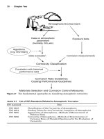
View looking east
FIGURE 20.32 Side view of rolls and the drive motors.
Motor B
Drive roll B
Idler roll
Motor A
Drive roll A
East
North
FIGURE 20.33 Top view of rolls and the drive motors.
Piotrowski / Shaft Alignment Handbook, Third Edition DK4322_C020 Final Proof page 660 27.9.2006 1:30am
660 Shaft Alignment Handbook, Third Edition
Motor A to drive shaft
−
80 W
Sag
compensated
readings
−
170
Roll A to drive shaft
+160
Sag
compensated
readings
−80
Motor B to drive shaft
Roll B to drive shaft
+90
−31
+55+35 −49
Drive roll B
Idler roll
Drive roll A
North target
South target
200 mils high
15 mils to the east
Reference
180 mils lower
27 mils to the west
Reference
65 mils lower
25 mils to the east
Reference
North target
South target
North target
South target
Shaft alignment information Roll alignment information
“Front side” face readings
Face reading diameter = 10 in.
Motor boundary condition information
Roll boundary condition information
Drive roll B
Idler roll
Drive roll A
North bearing
80 mils of shims
30 mils east
70 mils west
South bearing
40 mils of shims
70 mils east
35 mils west
North bearing
40 mils of shims
57 mils east
42 mils west
South bearing
250 mils of shims
70 mils east
37 mils west
North bearing
140 mils of shims
15 mils east
105 mils west
South bearing
110 mils of shims
100 mils east
22 mils west
Motor B
North bolts
160 mils of shims
95 mils east
10 mils west
South bolts
90 mils of shims
0 mils east
85 mils west
Motor A
North bolts
no shims
85 mils east
0 mils west
South bolts
110 mils of shims
35 mils east
55 mils west
T
B
E
W
0
T
B
E
−90
0
T
B
+85 WE +75
0
T
B
E
W
0
FIGURE 20.34 Shaft alignment, roll alignment, and boundary condition information.
Piotrowski / Shaft Alignment Handbook, Third Edition DK4322_C020 Final Proof page 661 27.9.2006 1:30am
Parallel Alignment 661
10 in.
Scale:
200 mils or 10 in.
Up
Side view
Motor A
Roll A
Motor B
Roll B
Idler roll
Baseplate or frame restriction points
Looking east
FIGURE 20.35
Side view of roll drive system.
Piotrowski / Shaft Alignment Handbook, Third Edition DK4322_C020 Final Proof page 662 27.9.2006 1:30am
662 Shaft Alignment Handbook, Third Edition
10 in.
Scale:
50 mils or 10 in.
East
Top view
Motor A
Roll A
Motor B
Roll B
Idler roll
Lateral movement restriction points
FIGURE 20.36
Top view of roll drive system.
Piotrowski / Shaft Alignment Handbook, Third Edition DK4322_C020 Final Proof page 663 27.9.2006 1:30am
Parallel Alignment 663
10 in.
Scale:
200 mils or 10 in.
Up
Side view
Motor A
Roll A
Motor B
Roll B
Idler roll
Baseplate or frame restriction points
Looking east
Add 80 mils
Pivot
Pivot
Add 110 mils
Remove 95 mils
Remove 110 mils
Add 290 mils
Remove 80 mils
Pivot
Remove 180 mils
FIGURE 20.37
(See color insert following page 322.) Side view alignment model
showing one possible solution.
Piotrowski / Shaft Alignment Handbook, Third Edition DK4322_C020 Final Proof page 664 27.9.2006 1:30am
664 Shaft Alignment Handbook, Third Edition
10 in.
Scale
:
50 mils or 10 in.
East
Top view
Motor A
Roll A
Motor B
Roll B
Idler roll
Lateral movement restriction points
35 mils west
Pivot
22 mils east
Pivot
20 mils west
Pivot
50 mils west
Pivot
60 mils west
Pivot
FIGURE 20.38
(See color insert following page 322.) Top view alignment model
showing one possible solution.
Piotrowski / Shaft Alignment Handbook, Third Edition DK4322_C020 Final Proof page 665 27.9.2006 1:30am
Parallel Alignment 665
Piotrowski / Shaft Alignment Handbook, Third Edition DK4322_C020 Final Proof page 666 27.9.2006 1:30am
21
Alignment Considerations for
Specific Types of Machinery
Up to this point, fairly broad generalizations have been made about rotating machinery. The
shaft alignment measurement methods and tools discussed in Chapter 10 through Chapter 15
did not mention any specific type of machinery that the methods should be used on.
Intentionally so, since most of these methods can be used on any type of machinery regardless
of their specific function. The rotating equipment could have been electric motors, steam
turbines, pumps, fans, compressors, or whatever. It really does not matter. The examples of
graphing and modeling techniques covered in Chapter 8 through Chapter 20 had specific
machine names on the diagrams, but for all practical purposes, the names of the machinery
were not relevant, only the graphing concepts. The OL2R methods discussed in Chapter 16
should work on virtually any type of machinery but certain OL2R methods are better suited
for certain situations than some of the others mentioned.
This is not to suggest however that a wide variety of rotating machinery behaves the same
way or should be aligned the same way. It is important to know a considerable amount of
information about each piece of machinery before, during, and after the alignment process.
Knowledge about how it works internally, what operational function does it perform, how
does the process affect its operational performance, and how it interacts with its frame and
foundation, and influence from external connections such as piping are important in thor-
ough understanding of the behavior of the machine. The example in Appendix A illustrates
the type of information that should be kept on each piece of rotating machinery.
This chapter will explore some of the specific information relating to alignment on common
rotating machinery equipment. Much of the information contained herein is based on actual
field measurements but should not be construed as hard and fast rules. Always consult the
manufacturer of the specific type of rotating machinery for information pertaining to your
particular machine. But above all, do your own investigative analysis and learn the behavior
of your machines.
Most of the OL2R movement ranges indicated in each machine category are based on
actual field measurements. These data indicate how the centerline of rotation of the shaft
might move from OL2R (or how the inboard and outboard bearing positions change from
OL2R and vice versa). The OL2R movement amounts reflect average ranges of motion; in
other words, the high end values could, and in many cases, have been in excess of the numbers
indicated, sometimes by a factor of 300% and up. Again, most manufacturers of rotating
machinery do not conduct OL2R measurements at a customer’s plant site. If you consult the
original equipment manufacturer for OL2R information, ask how the measurements were
taken, what the environmental and operational conditions were during the test, and why they
feel these data would be indicative of the machinery you have in operation.
The following information is an attempt to give you an overview of what to consider when
installing and aligning these different types of machinery. It is therefore recommended that
Piotrowski / Shaft Alignment Handbook, Third Edition DK4322_C021 Final Proof page 667 6.10.2006 12:19am
667
this information be used strictly as a starting point for you to initially align new rotating
machinery systems to allow you the opportunity to safely conduct field studies on your
rotating equipment.
21.1 DRIVERS
21.1.1 E
LECTRIC MOTORS
Electric motors (AC induction or synchronous or DC motors) are perhaps the best behaved
types of rotating machinery from an alignment standpoint. Electric motors up to 500 hp
frequently are outfitted today with antifriction-type bearings so they do not pose any major
installation problems assuming they are mechanically and electrically sound (Figure 21.1).
Medium to large electric motors are frequently outfitted with sliding-type bearings
(Figure 21.3). When power is applied to motors where the armatures are supported in
sliding-type bearings, the electromagnetic field wants to center the rotor with respect to the
stator field. This phenomenon is often referred to as ‘‘magnetic center’’ and needs to be taken
into consideration for proper shaft-to-shaft spacing. Many electric motors have no thrust
bearing per se and rely on electromagnetic forces to center the rotor. To find magnetic center,
uncouple the motor and run it ‘‘solo.’’ Once the field is applied, you may notice the shaft
‘‘hunting’’ back and forth axially for a short period of time and then it will typically settle out
at one specific axial position. Very carefully scribe a line on the rotating shaft with a felt tip
pen or soapstone near a stationary reference fixture such as the bearing seal. Keep your
fingers away from keys or keyways and do not let any loose clothing, tools, rags, or other
stationary objects attached to your body or near you hit the shaft. Drop the field (i.e., shut the
motor off) and let the rotor stop completely. It is unlikely that the shaft’s axial position is
directly on magnetic center so after safety tagging the breaker, hand rotate the shaft pushing
or pulling it axially until the scribe mark you made lines back up with the stationary reference
fixture you picked. Now measure and set the shaft-to-shaft distance with the machine it is
driving.
FIGURE 21.1 Typical small electric motor.
Piotrowski / Shaft Alignment Handbook, Third Edition DK4322_C021 Final Proof page 668 6.10.2006 12:19am
668 Shaft Alignment Handbook, Third Edition
If misalignment conditions are severe enough on electric motors and the shaft or armature
elastically bends a sufficient amount, the rotor to stator air gap can get out of tolerance (the
accepted tolerance for air gap eccentricity differential is +10% of the total air gap). From a
vibration standpoint, eccentric air gap problems will frequently exhibit a spectral peak at
twice line frequency (120 Hz in North America refer to Section 2.2.3).
Typical OL2R movement range of electric motors (horizontally mounted):
Vertical movement: 1 to 5 mils upward (5 to 200 hp); 3 to 30þ mils upward (200þ hp),
typically symmetrical (i.e., inboard and outboard ends move up the same amount)
Lateral (sideways) movement: 0 to 4 mils (usually much less than vertical movement)
Axial movement: 5 to 10 mils (5 to 200 hp); 8 to 50þ mils (200þ hp)
FIGURE 21.2 Medium size electric motor.
FIGURE 21.3 Large electric motor supported in sliding bearings.
Piotrowski / Shaft Alignment Handbook, Third Edition DK4322_C021 Final Proof page 669 6.10.2006 12:19am
Alignment Considerations for Specific Types of Machinery 669
21.1.1.1 Additional Information on Electric Motors
Moderate to excessive soft foot conditions have been experienced on virtually every size
motor regardless of frame construction design. Uneven air gap problems found occasionally
due to improper positioning of end bells or housing distortion due to uncorrected soft foot.
Inboard (coupling end) bearings may run hotter due to misalignment conditions. Excessive
vibration may be due to improperly bored coupling hubs. Infrared thermography surveys and
motor current signature analysis are very helpful in diagnosing problems.
21.1.2 STEAM TURBINES
Steam turbines can range in output from 20 to 100,000þ hp with speeds up to 25,000þ rpm
and therefore become some of the more interesting equipment for OL2R surveys and
consequentially some (Figure 21.4 through Figure 21.6) of the more difficult equipment to
maintain and operate properly. Steam pressures can range from 200 to 4000þ psig and
temperatures from 4008F to 11008F. Due to the fact that a high-temperature gas is used to
propel blades for shaft rotation, extensive frame and casing design considerations concerning
FIGURE 21.4 Small steam turbine with upper casing removed.
FIGURE 21.5 Small steam turbine.
Piotrowski / Shaft Alignment Handbook, Third Edition DK4322_C021 Final Proof page 670 6.10.2006 12:19am
670 Shaft Alignment Handbook, Third Edition
casing and rotor expansion and contraction are taken into account to minimize excessive
positional change of the rotor during operation. However, movement of the shaft invariably
occurs from OL2R conditions that can range considerably from unit to unit. In addition,
rotor expansion must be taken into consideration when selecting a flexible coupling to
prevent thrust transfer from one rotor to another, causing premature bearing or coupling
failure. On several occasions, the condensing end of the steam turbine has been observed to
move downward during operation. The cooler temperatures and the ‘‘vacuum draw down’’
effect of the condenser may actually move the condenser end opposite of what one might
expect. Again, since there is such a wide variety of equipment in existence, it is always best to
consult with your equipment manufacturer for initial installation, design modification, over-
haul, or operational problems with these units. Thank them for their input, but always do
your own research.
Typical OL2R movement range of steam turbines (horizontally mounted):
Vertical movement: –10þ to 25 mils upward (5 to 500 hp); 5 to 40þ mils upward (500þ hp),
typically asymmetrical (i.e., inboard and outboard ends do not move up the same amount)
Lateral (sideways) movement: 0 to 40þ mils (can be as much or considerably more than the
vertical movement)
Axial movement: 10 to 100þ mils (5 to 200 hp); 20 to 250þ mils (200þ hp)
21.1.2.1 Additional Information on Steam Turbines
Moderate to excessive off-line soft foot conditions have been experienced on virtually every size
steam turbine regardless of frame construction design. Frequently, on small- to medium-
sized steam turbines, one end of the casing is rigidly bolted to the frame and a ‘‘sway bar’’ or
flexible support is mounted at the other end to allow for axial expansion to occur to prevent
casing warpage during operation. Sometimes on larger steam turbines, the casing is keyed at the
casing centerline and the hold-down bolts are not tightened to lock the casing against the frame
support but are kept loose to allow for symmetric lateral and axial casing expansion to occur.
The lateral movement that occurs is often directly related to the expansion and contraction of
the steam piping connected to the steam turbine casing and proper design and installation of the
piping system is imperative to minimize static (off-line) and dynamic (running) nozzle loads.
FIGURE 21.6 Large steam turbine.
Piotrowski / Shaft Alignment Handbook, Third Edition DK4322_C021 Final Proof page 671 6.10.2006 12:19am
Alignment Considerations for Specific Types of Machinery 671
Most steam turbines are supported in sliding-type bearings and therefore exhibit a certain
amount of axial clearance between the thrust runner and the active–inactive thrust bearings
(often referred to as thrust float). When setting the machinery axial positions off-line, seat the
thrust runner against the active thrust bearing before measuring and adjusting the shaft-to-
shaft distance. Bear in mind that the axial movement amounts mentioned above are for the
casing and housing. The shaft may expand more than that and may influence how you should
set the off-line shaft end to shaft end distances.
21.1.3 GAS TURBINES
Industrial gas and power turbine drivers are used in a wide variety of applications ranging
from compression of gases and electrical generation to propulsion systems for ships
(Figure 21.7 and Figure 21.8). The Brayton cycle (i.e., a gas turbine) compresses air via a
FIGURE 21.7 Gas turbine.
FIGURE 21.8 Gas turbine driving an electric generator.
Piotrowski / Shaft Alignment Handbook, Third Edition DK4322_C021 Final Proof page 672 6.10.2006 12:19am
672 Shaft Alignment Handbook, Third Edition
centrifugal or axial flow compressor where the compressed air is mixed with fuel (liquid jet
fuel or natural gas) and burned. The hot, high-velocity gas then impinges on a series of several
stages of curved blade sets (power turbine) that is used to rotate the driven machinery.
Frequently, the gas and power turbines, although separate rotors supported in their own
bearings, share a common casing and frame. The residual high-velocity gas is then vented
through ductwork that sometimes houses a heat exchanger for a closed loop system or for use
in heating liquids for other purposes.
The gas turbine produces a tremendous amount of forward thrust in reaction to the high-
velocity gas escaping out of the tail end of the machine. A considerable amount of heat is
generated in the cycle and a twisting or torsional counter reaction occurs in the frame during
operation. These factors all contribute to some of the most radical OL2R machinery move-
ment in any type of driver used today.
Typical OL2R movement range of gas or power turbines:
Vertical movement: Intake end—10þ mils downward to 10þ mils upward; exhaust end—5
to 80þ mils upward
Lateral (sideways) movement: Intake end—2 to 20þ mils; exhaust end—2 to 60þ mils
Axial movement: See additional information
21.1.3.1 Additional Information on Gas Turbines
Moderate to excessive off-line soft foot conditions have been experienced on virtually every
size gas and power turbine regardless of frame construction design. Movement in the axial
direction from OL2R conditions can also be excessive. Forward movement of gas turbines
(i.e., toward the intake end) has been observed to translate 180þ mils. Gear- or diaphragm-
type couplings have been employed at the output shaft to drive the equipment. If the coupling
is a diaphragm-type (or any flexible disk-type) and there is movement toward the intake end,
damage could occur to the coupling and the thrust forces can be transmitted to the driven
machine. The shaft-to-shaft distance between the power turbine and the driven equipment
shaft is usually 40þ in. in an attempt to minimize the effect from large amounts of OL2R
movement and to minimize any heat transfer from the exhaust duct work to the driven
machine. Bear in mind that the axial movement amounts mentioned above are for the casing
and housing. The shaft may expand more than that and may influence how you should set the
off-line shaft end to shaft end distances.
21.1.4 INTERNAL COMBUSTION ENGINES
Very few field studies have been conducted (or at least published) on how internal combustion
engines move from OL2R conditions (Figure 21.9). Diesel engines, for example, are frequently
used to drive backup electrical generators, fire pumps, and portable air compressors. In the
wastewater treatment industry, biogas engines can be used to drive the air compressors. The
crankshaft is typically set very low in the casing and engine mounts can be found below, at, or
slightly above the centerline of rotation of the crankshaft. The relatively few studies that have
been done have still shown OL2R machinery movement regardless of the casing support
mounting location. Flexible coupling design is somewhat critical since variations in torque
occur as each piston delivers rotational force at varying intervals.
Typical OL2R movement range of internal combustion engines:
Vertical movement: 1 to 5 mils upward (5 to 200 hp); 2 to 20þ mils upward (200þ hp),
typically symmetrical (i.e., inboard and outboard ends move up the same amount)
Piotrowski / Shaft Alignment Handbook, Third Edition DK4322_C021 Final Proof page 673 6.10.2006 12:19am
Alignment Considerations for Specific Types of Machinery 673
Lateral (sideways) movement: 0 to 4 mils (usually much less than any vertical movement)
Axial movement: Unknown
21.1.4.1 Additional Information on Internal Combustion Engines
Moderate to excessive off-line soft foot conditions have been experienced on virtually every
size internal combustion engine regardless of frame construction design. On medium and
large engines, distortion of the engine frame during installation is a concern. To insure that
the crankshaft bearings are not distorted, web deflection tests are conducted as shown in
Figure 21.11 and Figure 21.12. A web deflection test determines if the distance between the
crank webs is changing when the crankshaft is rotated. If the bearings are misaligned due to
casing distortion, or there is an excessive amount of shaft misalignment with the coupling
engaged, the distance between the crank webs will vary when the crankshaft is rotated. If the
gap variation between the web is excessive, shims must be added between the engine and the
soleplates to relieve the distortion of the casing.
21.1.5 HORIZONTALLY MOUNTED CENTRIFUGAL PUMPS
Without a doubt, one of the most common drive systems in virtually every industry is a
motor-driven, horizontally mounted, centrifugal pump (Figure 21.13 through Figure 21.15).
There are several hundred designs of centrifugal pumps and it would be difficult to cover
every characteristic of each design used in industry. Their purpose is basically to move an
incompressible fluid from point A to point B. The temperature of the fluid conveyed has a
great effect on the OL2R conditions of the pump. As discussed in Chapter 5, the piping
attached to the pump can have a tremendous influence on obtaining and maintaining accurate
alignment, so that many people are unwilling to even try to reposition pumps, henceforth
declaring them the ‘‘stationary’’ machine when aligning them.
Typical OL2R movement range of centrifugal pumps:
Vertical movement: 0 to 80þ mils upward typically asymmetrical (i.e., inboard and out-
board ends do not move up the same amount)
FIGURE 21.9 Sixteen cylinder biogas engine coupled to a gearbox and compressor.
Piotrowski / Shaft Alignment Handbook, Third Edition DK4322_C021 Final Proof page 674 6.10.2006 12:19am
674 Shaft Alignment Handbook, Third Edition
52
60
60
78
78
64
50
50
53
20
32
34
70
76
76
85
89
77
97
107
108
82
92
92
96
100
96
115
121
128
132
132
139
103
105
88
50
3
2
2
10
5
50 20 5
2
2
2
5
5
5
50 20 20
5
5
10
5
50
25
10
3
5
10
2
25
5
2
2
50
25
5
10
2
5
10
20
10
2
2
10
3
North
3
5
5
5
FIGURE 21.10
Soft foot map between engine frame and soleplates on biogas
engine shown in Figure 21.9.
Piotrowski / Shaft Alignment Handbook, Third Edition DK4322_C021 Final Proof page 675 6.10.2006 12:19am
Alignment Considerations for Specific Types of Machinery 675
FIGURE 21.11 Inside dial gauge used to measure web deflection.
1
2
3
4
5
–1/4
–1/4
0
+1/4
+1/4
FIGURE 21.12 Web deflection measurements typically taken at five positions.
FIGURE 21.13 Single-stage centrifugal pumps with overhung impeller.
Piotrowski / Shaft Alignment Handbook, Third Edition DK4322_C021 Final Proof page 676 6.10.2006 12:19am
676 Shaft Alignment Handbook, Third Edition
Lateral (sideways) movement: 0 to 90þ mils (can be much greater than vertical movement
and is usually asymmetrical)
Axial movement: 0 to 150þ mils, frequently dependent on temperature of process fluid
21.1.5.1 Additional Information on Horizontally Mounted Centrifugal Pumps
Moderate to excessive off-line soft foot conditions have been experienced on virtually every
centrifugal pump regardless of frame construction design. Maintaining long-term alignment
of ANSI- and API-type pumps can be difficult due to the loosely supported inboard (coup-
ling) end of the pump case. Failure of mechanical seals can often be attributed to misalign-
ment conditions. Excessive leakage on mechanically packed pumps can also be attributed to
misalignment conditions. Pumps can experience internal rubs due to rotor distortion caused
FIGURE 21.14 Single-stage centrifugal pump with centered impeller.
FIGURE 21.15 Multistage centrifugal pump.
Piotrowski / Shaft Alignment Handbook, Third Edition DK4322_C021 Final Proof page 677 6.10.2006 12:19am
Alignment Considerations for Specific Types of Machinery 677
by moderate to excessive misalignment conditions. Bear in mind that the axial movement
amounts mentioned above are for the casing and housing. The shaft may expand more than
that and may influence how you should set the off-line shaft end to shaft end distances.
21.1.6 VERTICALLY MOUNTED CENTRIFUGAL PUMPS
There are several different types of vertical pumps such as well water pumps, in-line pumps,
and reactor coolant pumps. In most cases, vertical pumps are driven by C-flanged motors.
These motors are bolted to a cylindrical casting that is attached to the pump casing. In some
situations, the pump is supported in its own bearings and the motor is flexibly coupled to the
pump. In other situations, the pump is rigidly coupled to the motor shaft and the thrust load
is supported by a thrust or radial bearing at the top of the motor. The assumption that many
people have is that no alignment is required for these types of machines since the motor,
connector casting, and pump casing are perfectly machined, rabbeted fits that precisely align
the motor shaft to the pump shaft. In most cases, this is not true. Misalignment can and does
occur on these types of drives as often as a horizontally mounted drive system (Figure 21.16
through Figure 21.18).
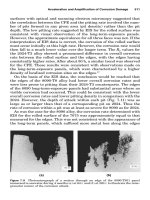
Figure 21.19 shows a large vertical pump driven by a 2500-hp motor, which is bolted to the
pump casing with 12 bolts. The pump was new and was experiencing excessive vibration
where misalignment was suspected as the cause. The coupling connecting the motor shaft to
the pump shaft is a rigid coupling. The upper bearing of the motor has a thrust bearing that
supports the weight of the armature and the weight of the pump shaft. Upper and lower
bronze bushings act as the radial bearings for the pump shaft. These bushings are lubricated
by the water that is pumped upward from the impeller at the lower end of the pump shaft.
FIGURE 21.16 Small vertical pumps.
Piotrowski / Shaft Alignment Handbook, Third Edition DK4322_C021 Final Proof page 678 6.10.2006 12:19am
678 Shaft Alignment Handbook, Third Edition
As mentioned previously, any attempt to align shafts that are connected together with a
rigid coupling are futile. The misalignment can be severe and the shafts will elastically bend to
accommodate the misalignment condition making it appear that the alignment is acceptable
when capturing readings across the engaged rigid coupling. To properly align a unit like this,
the coupling must be disengaged. In doing that however, the pump shaft drops down from its
own weight and the impeller touches the housing at the bottom. Any attempt to rotate the
pump shaft after the coupling has been disengaged can potentially damage the impeller. Since
the motor shaft can still be rotated, either the face–rim or double radial alignment methods
could be used. In this particular case, the double radial method was used to check the
alignment between the two shafts. Before disconnecting the coupling however, runout mea-
surements can be taken to determine if the coupling hubs are bored properly (i.e., concentric)
and if the motor or pump shafts are permanently bent. Figure 21.20 shows the runout
measured on the shafts and the coupling hubs.
After the runout measurements were taken, the mechanical seal was removed and the
coupling was disengaged. The specified distance between the end of the motor shaft and
the end of the pump shaft was 0.250 in. There is an adjustment nut on the top of the pump
FIGURE 21.17 Medium-sized vertical pumps.
FIGURE 21.18 Large vertical pumps.
Piotrowski / Shaft Alignment Handbook, Third Edition DK4322_C021 Final Proof page 679 6.10.2006 12:19am
Alignment Considerations for Specific Types of Machinery 679
FIGURE 21.19 Vertical pump.
8 mils
8 mils
11 mils
7 mils
6 mils
12 mils
Angular location of
high spot viewed from
above referenced to
pump key in clockwise
direction
Total indicated
runout (TIR)
290
120
120
120
120
290
As found gap between rotating
mechanical seal cartridge and top of
stuffing box = 0.293 in.
As found adjusting nut to coupling
spool clearance with coupling bolts
removed = 0.263 in.
FIGURE 21.20 Runout measurements taken on pump shown in Figure 21.19.
Piotrowski / Shaft Alignment Handbook, Third Edition DK4322_C021 Final Proof page 680 6.10.2006 12:19am
680 Shaft Alignment Handbook, Third Edition
shaft that can be rotated to obtain the desired shaft-to-shaft distance with the coupling
disengaged. The pump shaft was then centered in its upper bushing as shown in Figure
21.21 and Figure 21.22. Feeler gauges were used to measure four points between the shaft
and the bushing as shown in Figure 21.23. The specified total radial clearance in the bushing
was to range from 6 to 12 mils. Notice that the measured gaps exceed the specified amount
and that they are not the same in the east to west direction compared to the north to south
direction.
Now the pump shaft is centered in the upper bushing and the coupling disengaged,
alignment readings can be taken between the shafts. Figure 21.24 shows capturing
the alignment reading on the adjustment nut and Figure 21.25 shows capturing the alignment
reading on the pump shaft just above the stuffing box area. Another reading was taken on
the balance ring just below the adjustment nut. The as-found alignment readings are shown
in Figure 21.26.
To plot the misalignment condition, two views will be generated. One view will show the
misalignment in the north to south direction as shown in Figure 21.27 and another view will
show the misalignment in the east to west direction as shown in Figure 21.28. A T-bar overlay
will be used in this modeling method. The top part of the T-bar overlay will represent
the mating flange surface where the motor bolts to the pump housing. Each bolting plane
has been scaled off on the top part of the T. Carefully study the bolt plane designations in
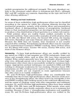
FIGURE 21.21 Centering the pump shaft in its upper bushing.
Piotrowski / Shaft Alignment Handbook, Third Edition DK4322_C021 Final Proof page 681 6.10.2006 12:19am
Alignment Considerations for Specific Types of Machinery 681
Figure 21.27 and Figure 21.28. The base to the T-bar overlay will represent the centerline of
rotation of the motor shaft.
Since there was runout observed on the motor and pump coupling hubs, before disengaging
the coupling, the shafts were rotated so that the high spots were placed on the north side of
the shafts. With the high spots physically positioned on the north side, we can compensate for
FIGURE 21.22 Wooden wedges were used to keep the pump shaft centered.
North
South
East
West
24 mils
24 mils
8 mils
8 mils
Pump shaft
Upper pump bearing
FIGURE 21.23 Gap measurements at the upper bushing of the pump.
Piotrowski / Shaft Alignment Handbook, Third Edition DK4322_C021 Final Proof page 682 6.10.2006 12:19am
682 Shaft Alignment Handbook, Third Edition
the eccentricity and determine where the actual centerline of rotation of the pump shaft is as
shown in Figure 21.26.
The top part of the T-bar overlay shows what thickness of shims need to be installed
between each of the 12 bolts that mate the motor housing to the pump housing to correct for
the angular misalignment. Bear in mind that each of the 12 flange bolts appear in both views
and that there is an angular misalignment condition in both views. Bolt by bolt, add the
number of shims required to correct the angular misalignment from the north–south and
east–west views. Once the shim totals for each bolt have been added together, determine
FIGURE 21.24 Alignment readings taken at the top of the pump shaft at the adjustment nut.
FIGURE 21.25 Alignment readings taken at the bottom of the pump shaft just above the stuffing box.
Piotrowski / Shaft Alignment Handbook, Third Edition DK4322_C021 Final Proof page 683 6.10.2006 12:19am
Alignment Considerations for Specific Types of Machinery 683
which bolt requires the least amount of shims and subtract that amount from all the bolts as
shown in Figure 21.29. Ironically, the least amount of shims happens to occur at bolt A.
At this point, all of the bolts were loosened and soft foot gaps were measured at each bolt as
shown in Figure 21.30. Improper contact can occur on these types of machines also.
As-found alignment readings
Balance ring
N
S
WE
0
Pump shaft
N
S
W
0
Adjustment nut
N
S
WE
0
0
50
10
40
20
30
+
_
10
40
20
30
0
50
10
40
20
30
+
_
10
40
20
30
0
50
10
40
20
30
+
_
10
40
20
30
14 in.
5.5 in.
4 in.
10.5 in.
+50
0
−53
+54
+4
−53
+58
+14
−49
E
FIGURE 21.26 As-found double radial alignment measurements.
180 wide x 100 tall grid
Apparent pump shaft centerline
(i.e., outer surface with runout)
Scale:
5 in.
and 10 mils
5 in.
and 10 mils
South
North
Balance ring measurement plane
Pump shaft measurement plane
Adjusting nut measurement plane
30.4 in.
22.27 in.
8.
15
in.
63
in.
bolt circle diameter
0NS
0NS
0NS
Adjusting nut
Balance ring
Pump shaft
0
+4
+13
Motor shaft centerli
ne
Apparent motor to pump
housing flange mating plane
F–G bolt plane
add 12 mils
E–H bolt plane
add 11 mils
D–I bolt plane
add 8 mils
C–J bolt plane
add 5 mils
B–K bolt plane
add 2 mils
A–L bolt plane
add 0 mils
Translate 3 mils to the south
Actual pump shaft centerline of rotation
(i.e., compensated for runout)
Adjusted motor to pump
housing flange mating plane
12 mils TIR here
11 mils TIR here
6 mils TIR here
0
50
10
40
20
30
+
_
10
40
20
30
0
50
10
40
20
30
+
_
10
40
20
30
0
50
10
40
20
30
+
_
10
40
20
30
FIGURE 21.27 (See color insert following page 322.) As-found alignment model of motor and pump
shaft as viewed in the north to south direction.
Piotrowski / Shaft Alignment Handbook, Third Edition DK4322_C021 Final Proof page 684 6.10.2006 12:19am
684 Shaft Alignment Handbook, Third Edition