Handbook Of Shaft Alignment Episode 3 Part 7 ppt
Bạn đang xem bản rút gọn của tài liệu. Xem và tải ngay bản đầy đủ của tài liệu tại đây (337.88 KB, 30 trang )
1990—Malcolm Murray files U.S. patent for vernier-strobe method used to measure
off-line to running machinery movement data.
1991—Dieter Busch files U.S. patent for laser–detector–prism system used to measure
off-line to running machinery movement data. Paul Saunders files U.S. patent for
electronic shaft alignment system utilizing optical encoder.
There you have it. A brief run through the last 6000 years of human existence, illustrating
the engineering triumphs during periods of unparalleled growth in science and technology
interspersed with periods of dismal ignorance. In many cases, it is not clear who actually
‘‘invented’’ certain methods and devices.
The vast majority of U.S. patents for aligning and leveling machinery filed from 1860 to
1946 fell into the following categories:
24
28
10
22
17
27
30
29
31
11
23
15
20
21
25
14
18
13
12
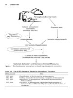
FIGURE 22.17 Callahan’s shaft alignment device, 1953.
17
Driving
shaft
49
3
47
48
51
34
59
56
57
56
18
Driven
shaft
52
52
43
3
46
58
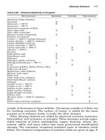
FIGURE 22.18 Bently’s shaft alignment device, 1974.
Piotrowski / Shaft Alignment Handbook, Third Edition DK4322_C022 Final Proof page 750 26.9.2006 8:51pm
750 Shaft Alignment Handbook, Third Edition
.
Use of spirit=dumpy levels to set the positions of shafts in line with each other
.
Centering devices for work pieces on lathes
.
Use of a tight wire for alignment of engine cylinder bores
The technology of shaft alignment as we recognize it today, really did not emerge until the
1940s and 1950s followed by a flurry of patent activity that persists to the present day.
Between 1860 and 1950, only 11 U.S. patents were filed relating to measuring off-line shaft
centerline positions, the majority of which exclusively dealt with aligning and leveling line
shafts typically used in the paper industry. Over 60 years had passed since John Logan
patented the dial indicator before Joseph Christian actually filed a patent using this device
for alignment of rotating machinery shafts.
However, this does not necessarily mean that shaft alignment was not performed on
rotating machinery during the early part of the Industrial Revolution. As we have seen
throughout history, several methods and devices had been in existence for long periods of
time before legal patent documents were filed claiming their originality. Regrettably, the true
inventors of these mechanisms and procedures will probably never be known.
BIBLIOGRAPHY
Abbott, D. (1986) Engineers & Inventors, Peter Bedrick Books Inc., New York.
Amelio, G.F. et al. (1970) Experimental verification of the charge-coupled device concept. Bell Syst.
Tech. J., 49, 593–600.
Brotherton, M. (1964) Masers and Lasers, McGraw Hill Book Co., New York.
Boyle, W.S. and Smith, G.E. (1970) Charge-coupled semiconductor devices. Bell Syst. Tech. J., 49,
587–593.
66 Centuries of Measurement, Sheffield Corporation, Dayton, OH, 1987.
Encyclopedia Britannica, various volumes.
Garrison, E.G.A Historyof Engineering and Technology: Artful Methods, CRC Press Inc.,Boca Raton,FL.
Grun, B. (1991) The Timetables of History, Simon & Schuster Inc., New York.
Hecht, J. (1992) The Laser Guidebook, McGraw Hill, New York.
Mancuso, J. (1986) Couplings and Joints, Marcel Dekker Inc., New York.
Mills, J.F. (1983) Encyclopedia of Antique Scientific Instruments, Facts on File Inc., New York.
29
3
26
19
25
11
3
13a
49
45
34f
44
35
48
3
40
38
42
34e
32
34d
31
B
18
8
15
12a
21
20
27
28
2
23a
23b
23c
23d
24
10
12
2
50
47
46
43
39
41
37
34b
34a
36
34c
33
30
17
A
9
22
16
14
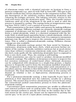
FIGURE 22.19 Murray’s shaft alignment device, 1983.
Piotrowski / Shaft Alignment Handbook, Third Edition DK4322_C022 Final Proof page 751 26.9.2006 8:51pm
The History of Machinery Alignment 751
Piotrowski / Shaft Alignment Handbook, Third Edition DK4322_C022 Final Proof page 752 26.9.2006 8:51pm
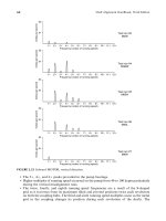
Appendix A
Machinery Data Card
Scale:
Top view
East
up
Side view
Scale:
Shaft alignment information
Reverse indicator Face–peripheral
Shaft to coupling spool
Double radial
Face–face
Laser LVDT Prox probe Other
“Desired” dial indicator readings
(No bracket sag)
Indicate where any soft foot corrections were made, the shape and
thickness of the shims or custom wedges, and indicate how the
corrections are oriented under each of the machinery feet.
Top view of machinery
T
B
0
T
B
0
Desired off—Line vertical shaft positions Desired off—Line lateral shaft positions
Maintenance history
Date
W
ork performed
Date of installation
Mfg. Model No. Serial No.
Shaft-to-shaft spacing
Coupling information
Elastomeric Flex discGear Diaphragm Metal ribbon Other
Chain
in.
±
Bolt torque ft-lb Wrench size in.
Driver shaft diameter
in.
Interference fit
mils Shaft taper in. ft
Lubrication info
Oil
Grease
Continuous feed oil
Viscosity or type
Recommended Mfg. Secondary Mfg.
Amount of lube oz/pints
Driven shaft diameter in. Interference fit mils Shaft taper in. ft
in.
±
in.
±
in.
(continued )
Piotrowski / Shaft Alignment Handbook, Third Edition DK4322_A001 Final Proof page 753 29.9.2006 7:46pm
753
Mfg. Model No. Serial No.
HP RPM
Service factorTrip speed
Speed
Driver unit Information
“Critical” speed(s)
Steam turbine Gas turbineInduction motor Synchronous motor Diesel Other
Bearing information
Inboard (coupling) Brg.
Outboard Brg.
Total unit weight/rotor weight
lb/
RPM RPM
Mfg. Mdl./Brg. No. Clearance
Mfg. Mdl./Brg. No. Clearance
Antifriction SlidingType of bearings:
Thrust Brg.
Mfg. Mdl./Brg. No. Axial float
Off-line to running machinery movement
Outboard end
Inboard end
Lateral movement
Vertical movement
N S E W
mils Up Down mils
N S E W
mils Up Down mils
Foot bolt size
Wrench size
in.
in.
Mfg. Model No. Serial No.
HP RPM
Service factorTrip speed
Speed
Driven unit Information
“Critical” speed(s)
Compressor GeneratorPump Gear Fan Other
Bearing information
Inboard (coupling) Brg.
Outboard Brg.
Total unit weight/rotor weight
lb/
RPM RPM
Mfg. Mdl./Brg. No. Clearance
Mfg. Mdl./Brg. No. Clearance
Type of bearings:
Thrust Brg.
Mfg. Mdl./Brg. No. Axial float
Off-line to running machinery movement
Outboard end
Inboard end
Lateral movementVertical movement
N S E W
mils Up Down mils
N S E W
mils Up Down mils
Foot bolt size
Wrench size
in.
in.
Machinery data card
Equipment photo/sketch
Equipment name
Location
Magnetic
Antifriction Sliding Magnetic
Appendix A (continued )
Piotrowski / Shaft Alignment Handbook, Third Edition DK4322_A001 Final Proof page 754 29.9.2006 7:46pm
754 Shaft Alignment Handbook, Third Edition
Appendix B
Sample Preliminary Alignment
Record Sheet
Indicate where any “soft foot” corrections were made,
the shape and thickness of the shims or custom “wedges,”
and indicate how the corrections are oriented under each of
the machinery feet.
Preliminary alignment checks
Company: _______________________________
Equipment name: __________________________
Location: ________________________________
Equipment identification #: ___________________
Static piping stress checks
Date: ______________
Dial indicators were located on the . . .
OMotor OPump
With piping attached and after
loosening the pump foot bolts, the dial
indicators read the following values . . .
________ mils vertical
________ mils lateral/horizontal
Key
Key
Motor shaft
Pump shaft
Shaft and coupling hub runout checks
Date: _______
Piping stress test by: _________________
Runout checks by: __________________
“Soft Foot” checks by: _________________
Notes:
___________________________________________________
___________________________________________________
___________________________________________________
__________________________________________________
“Soft Foot” checks and corrections
Loosen or remove all foot bolts. Clean underside of machinery
feet and points of contact on baseplate. Rough align both units.
With the foot bolts in place but not tightened down, measure four
points around each bolt hole with a set of feeler gauges and record
the readings.
Piotrowski / Shaft Alignment Handbook, Third Edition DK4322_A001 Final Proof page 755 29.9.2006 7:46pm
755
Piotrowski / Shaft Alignment Handbook, Third Edition DK4322_A001 Final Proof page 756 29.9.2006 7:46pm
Appendix C
Sample Installation
and Shaft Alignment
Report record sheet
Installation and shaft alignment report
Company: _______________________________
Equipment name: __________________________
Location: ________________________________
Equipment identification #: ___________________
Static piping stress checks
Date: ______________
Dial indicators were located on the . . .
OMotor OPump
With piping attached and after
loosening the pump foot bolts, the dial
indicators read the following values . . .
________ mils vertical
________ mils lateral/horizontal
Key
Key
Motor shaft
Pump shaft
Shaft and coupling hub runout checks
Date: _______
Piping stress test by: _________________
Runout checks by: __________________
“Soft Foot” checks by: _________________
Final alignment readings by: ___________
Shaft alignment information
“Desired” / “Shoot-for”
Dial indicator readings
T
B
0
T
B
0
Indicate how the shaft positions were
measured with the machinery off-line.
T
B
0
T
B
0
Final readings
OReverse indicator OFace–peripheral
OShaft to Coupling spool OFace–face
ODouble radial OLaser O Other __________
Amount of bracket sag ________ mils
Indicate where any “soft foot” corrections were made, the shape and
thickness of the shims or custom “wedges”, and indicate how the
corrections are oriented under each of the machinery feet.
“Soft Foot” checks and corrections
Piotrowski / Shaft Alignment Handbook, Third Edition DK4322_A001 Final Proof page 757 29.9.2006 7:46pm
757
Piotrowski / Shaft Alignment Handbook, Third Edition DK4322_A001 Final Proof page 758 29.9.2006 7:46pm
Appendix D
Torque Values
(SAE Grade 2 Bolts)
Recommended Torque Values for SAE Grade 2 Nuts and Bolts Unified National
Coarse (UNC)
Bolt Size (in.) Threads per Inch Torque (Dry)
Torque (Lubricated)
(75% of Dry Torque)
Clamp Load
(lbf 1=225%)
0.164 32 19 in lb 14 in lb 546
0.19 24 28 in lb 21 in lb 734
0.25 20 67 in lb 50 in lb 1,313
0.3125 18 120 in lb 90 in lb 2,175
0.375 16 21 ft-lb 16 ft-lb 3,188
0.4375 14 32 ft-lb 24 ft-lb 4,388
0.5 13 52 ft-lb 39 ft-lb 5,850
0.5625 12 69 ft-lb 52 ft-lb 7,500
0.625 11 100 ft-lb 75 ft-lb 9,300
0.75 10 190 ft-lb 142 ft-lb 13,800
0.875 9 293 ft-lb 220 ft-lb 11,400
1 8 427 ft-lb 320 ft-lb 15,000
1.125 7 8,678 ft-lb 650 ft-lb 18,900
1.25 7 1,155 ft-lb 865 ft-lb 24,000
1.375 6 1,467 ft-lb 1,100 ft-lb 28,575
1.5 6 1,667 ft-lb 1,250 ft-lb 34,800
(55 kpsi proof strength–69 kpsi tensile strength for sizes 0.250 ft to 0.500 in.)
(52 kpsi proof strength–64 kpsi tensile strength for sizes 0.500 ft to 0.750 in.)
(28 kpsi proof strength–55 kpsi tensile strength for sizes 0.750 ft to 1.500 in.)
Recommended Torque Values for SAE Grade 2 Nuts and Bolts Unified National Fine (UNF)
Bolt Size (in.) Threads per Inch Torque (Dry)
Torque (Lubricated)
(75% of Dry Torque)
Clamp Load
(lbf 1=225%)
0.164 36 23 in lb 17 in lb 622
0.19 32 35 in lb 26 in lb 852
0.25 28 75 in lb 56 in lb 1,500
0.3125 24 156 in lb 108 in lb 2,400
0.375 24 23 ft-lb 18 ft-lb 3,600
0.4375 20 37 ft-lb 28 ft-lb 4,913
0.5 20 55 ft-lb 41 ft-lb 6,600
0.5625 18 80 ft-lb 60 ft-lb 8,400
0.625 18 110 ft-lb 83 ft-lb 10,575
(continued )
Piotrowski / Shaft Alignment Handbook, Third Edition DK4322_A001 Final Proof page 759 29.9.2006 7:46pm
759
Appendix D (continued)
Bolt Size (in.) Threads per Inch Torque (Dry)
Torque (Lubricated)
(75% of Dry Torque)
Clamp Load
(lbf 1=225%)
0.75 16 192 ft-lb 144 ft-lb 1,5375
0.875 14 184 ft-lb 138 ft-lb 1,2600
1 12 274 ft-lb 205 ft-lb 1,6425
1 14 280 ft-lb 210 ft-lb 1,6800
1.125 12 397 ft-lb 297 ft-lb 21,150
1.25 12 553 ft-lb 415 ft-lb 26,550
1.375 12 746 ft-lb 559 ft-lb 32,550
1.5 12 979 ft-lb 734 ft-lb 39,150
(55 kpsi proof strength–69 kpsi tensile strength for sizes 0.250 ft to 0.500 in.)
(52 kpsi proof strength–64 kpsi tensile strength for sizes 0.500 ft to 0.750 in.)
(28 kpsi proof strength–55 kpsi tensile strength for sizes 0.750 ft to 1.500 in.)
Piotrowski / Shaft Alignment Handbook, Third Edition DK4322_A001 Final Proof page 760 29.9.2006 7:46pm
760 Shaft Alignment Handbook, Third Edition
Appendix E
Torque Values
(SAE Grade 5 Bolts)
Recommended Torque Values for SAE Grade 5 Nuts and Bolts Unified National
Coarse (UNC)
Bolt Size (in.) Threads per Inch Torque (Dry)
Torque (Lubricated)
(75% of Dry Torque)
Clamp Load
(lbf 1=225%)
0.164 32 52 in lb 40 in lb 890
0.19 24 73 in lb 55 in lb 1,114
0.25 20 96 in lb 76 in lb 2,025
0.3125 18 204 in lb 156in lb 3,338
0.375 16 31 ft-lb 23 ft-lb 4,950
0.4375 14 50 ft-lb 37 ft-lb 6,788
0.5 13 76 ft-lb 57 ft-lb 9,075
0.5625 12 109 ft-lb 82 ft-lb 11,625
0.625 11 150 ft-lb 112 ft-lb 14,400
0.75 10 266 ft-lb 200 ft-lb 21,300
0.875 9 430 ft-lb 322 ft-lb 29,475
1 8 644 ft-lb 483 ft-lb 38,625
1.125 7 794 ft-lb 596 ft-lb 42,375
1.25 7 1,120 ft-lb 840 ft-lb 53,775
1.375 6 1,470 ft-lb 1,100 ft-lb 64,125
1.5 6 1,950 ft-lb 1,462 ft-lb 78,000
(85 kpsi proof strength–120 kpsi tensile strength for sizes 0.250 ft to 0.750 in.)
(78 kpsi proof strength–115 kpsi tensile strength for sizes 0.750 ft to 1.000 in.)
(74 kpsi proof strength–105.5 kpsi tensile strength for sizes 1.000 ft to 1.500 in.)
Recommended Torque Values for SAE Grade 5 Nuts and Bolts Unified National Fine (UNF)
Bolt Size (in.) Threads per Inch Torque (Dry)
Torque (Lubricated)
(75% of Dry Torque)
Clamp Load
(lbf 1=225%)
0.164 36 53 in lb 40 in lb 1,023
0.19 32 66 in lb 49 in lb 1,279
0.25 28 120 in lb 87 in lb 2,325
0.3125 24 228 in lb 168in lb 3,675
0.375 24 35 ft-lb 26 ft-lb 5,588
0.4375 20 55 ft-lb 41 ft-lb 7,575
0.5 20 85 ft-lb 64 ft-lb 10,200
0.5625 18 122 ft-lb 91 ft-lb 12,975
0.625 18 170 ft-lb 128 ft-lb 16,350
(continued )
Piotrowski / Shaft Alignment Handbook, Third Edition DK4322_A001 Final Proof page 761 29.9.2006 7:46pm
761
Appendix E (continued)
Bolt Size (in.) Threads per Inch Torque (Dry)
Torque (Lubricated)
(75% of Dry Torque)
Clamp Load
(lbf 1=225%)
0.75 16 297 ft-lb 223 ft-lb 23,775
0.875 14 474 ft-lb 355 ft-lb 32,475
1 12 705 ft-lb 529 ft-lb 42,300
1 14 721 ft-lb 541 ft-lb 32,275
1.125 12 890 ft-lb 668 ft-lb 47,475
1.25 12 1,241 ft-lb 930 ft-lb 59,550
1.375 12 1,672 ft-lb 1,254 ft-lb 72,975
1.5 12 2,194 ft-lb 1,645 ft-lb 87,750
(85 kpsi proof strength–120 kpsi tensile strength for sizes 0.250 ft to 0.750 in.)
(78 kpsi proof strength–115 kpsi tensile strength for sizes 0.750 ft to 1.000 in.)
(74 kpsi proof strength–105.5 kpsi tensile strength for sizes 1.000 ft to 1.500 in.)
Piotrowski / Shaft Alignment Handbook, Third Edition DK4322_A001 Final Proof page 762 29.9.2006 7:46pm
762 Shaft Alignment Handbook, Third Edition
Appendix F
Torque Values
(SAE Grade 8 Bolts)
Recommended Torque Values for SAE Grade 8 Nuts and Bolts Unified National Coarse
(UNC)
Bolt Size (in.) Threads per Inch Torque (Dry)
Torque (Lubricated)
(75% of Dry Torque)
Clamp Load
(lbf 1=225%)
0.138 32 22 in lb 16 in lb 815
0.164 32 41 in lb 31 in lb 1,254
0.19 24 59 in lb 44 in lb 1,568
0.25 20 143 in lb 107in lb 2,850
0.3125 18 24 ft-lb 18 ft-lb 4,725
0.375 16 43 ft-lb 32 ft-lb 6,975
0.4375 14 69 ft-lb 52 ft-lb 9,600
0.5 13 106 ft-lb 79 ft-lb 12,750
0.5625 12 153 ft-lb 115 ft-lb 16,350
0.625 11 211 ft-lb 158 ft-lb 20,325
0.75 10 376 ft-lb 282 ft-lb 30,075
0.875 9 606 ft-lb 454 ft-lb 41,550
1 8 908 ft-lb 681 ft-lb 54,525
1.125 7 1.288 ft-lb 966 ft-lb 68,700
1.125 7 1.288 ft-lb 966 ft-lb 68,700
1.25 7 1.817 ft-lb 1362 ft-lb 87,225
1.375 6 2.381 ft-lb 1786 ft-lb 1,03950
1.5 6 3.161 ft-lb 2371 ft-lb 1,26450
(120 kpsi proof strength–150 kpsi tensile strength for sizes 0.250 ft to 1.500 in.)
Recommended Torque Values for SAE Grade 8 Nuts and Bolts Unified National Fine (UNF)
Bolt Size (in.) Threads per Inch Torque (Dry)
Torque (Lubricated)
(75% of Dry Torque)
Clamp Load
(lbf 1=225%)
0.138 40 25 in lb 18 in lb 910
0.164 36 43 in lb 32 in lb 1,321
0.19 32 68 in lb 51 in lb 1,792
0.25 28 163 in lb 122in lb 3,263
0.3125 24 27 ft-lb 20 ft-lb 5,113
0.375 24 49 ft-lb 37 ft-lb 7,875
0.4375 20 77 ft-lb 58 ft-lb 10,650
0.5 20 119 ft-lb 89 ft-lb 14,400
0.5625 18 171 ft-lb 128 ft-lb 18,300
(continued )
Piotrowski / Shaft Alignment Handbook, Third Edition DK4322_A001 Final Proof page 763 29.9.2006 7:46pm
763
Appendix F (continued)
Bolt Size (in.) Threads per Inch Torque (Dry)
Torque (Lubricated)
(75% of Dry Torque)
Clamp Load
(lbf 1=225%)
0.625 18 239 ft-lb 179 ft-lb 2,3025
0.75 16 419 ft-lb 314 ft-lb 3,3600
0.875 14 668 ft-lb 501 ft-lb 4,5825
1 12 994 ft-lb 745 ft-lb 5,9700
1 14 1,019 ft-lb 764 ft-lb 6,1125
1.125 12 1,444 ft-lb 1,083 ft-lb 7,7025
1.25 12 2,011 ft-lb 1,508 ft-lb 9,6600
1.375 12 2,711 ft-lb 2,033 ft-lb 11,8350
1.5 12 3,557 ft-lb 2,667 ft-lb 14,2275
(120 kpsi proof strength–150 kpsi tensile strength for sizes. 0.250 ft to 1.500 in.)
Piotrowski / Shaft Alignment Handbook, Third Edition DK4322_A001 Final Proof page 764 29.9.2006 7:46pm
764 Shaft Alignment Handbook, Third Edition
Appendix G
Shaft Alignment and Related
U.S. Patents
US Patent # Held by Month Day Year Description
39608 Williams August 18 1863 Shaft centerer
283627 John Logan August 21 1883 Improvement to gauges (dial indicator)
431054 Henderson July 1 1890 Pipe clamping device
458055 George Hunt December 30 1890 Gage for aligning engines
487427 Poole December 6 1892 Level hanger for shafting
521306 Humphrey Campbell June 26 1893 Shaft setting device
541754 Isgrig June 25 1895 Line shaft alignment
575857 Sly January 26 1897 Lantern bracket
651024 Thomas June 5 1900 Aligning and leveling instrument for shafting
679591 James Barns March 27 1901 Centering device for lining up engines
685288 Miller October 29 1901 Indicator for lathes
685290 John C. Miller March 9 1901 Aligning work piece to CL of lathe spindle
685455 Kinkead October 29 1901 Instrument for hanging and lining up shafting
807085 Newton December 12 1905 Shaft aligner
868074 Ernest Clark April 13 1906 Shaft liner and leveler
958736 Edgar Ferris August 26 1908 Shaft aligning device
1221507 Buesse April 3 1917 Pipe clamp base
1231479 Blumer June 26 1917 Roll locating device
1295936 Spellman March 4 1919 Measuring instrument
1339384 Douglas May 11 1920 Gage
1351663 Koch August 31 1920 Measurement gage comparator
1477257 Lewis Fritz July 8 1922 Shaft alignment gauge
1505313 Alvah J. Colwell June 16 1923 Crank shaft throw parallel gauge
1516288 Frank Godfrey April 5 1924 Bevel protractor
1559230 William Eccles January 22 1921 Aligning meter for gears and shafts
1591485 Albert Guillet August 25 1925 Lining block and measure for leveling machinery
1616084 Albert Guillet April 1 1926 Leveling and lining spinning frames
1799739 John Elering, et al. November 13 1926 Precision measuring device
1907959 Albert Guillet April 7 1928 Lining and leveling means for machinery
2395393 Arche Brilliantine June 3 1944 Electric alignment micrometer
2402567 Milner October airfoils
2451720 Davis October 19 1948 Centering device
2461143 Clifford February 8 1949 Gaging device=shaft bracket
2499753 Hubbard May 2 1946 Chain tightening and securing device
2516854 Joseph Christian January 16 1946 Gauging apparatus for aligning shafts
2624944 Pujda, A.G. January 13 1953 Layout measuring tool
2634939 Robert Voss July 2 1949 Shaft aligning mechanism
2638676 Callahan May alignment device
2656607 Harding October device
2692527 Wetzel, T.A. October 26 1954 Optical aligning apparatus for machine tools
2703505 Senn, J.A. March 8 1955 Apparatus for aligning machine elements
(continued )
Piotrowski / Shaft Alignment Handbook, Third Edition DK4322_A001 Final Proof page 765 29.9.2006 7:46pm
765
Appendix G (continued)
US Patent # Held by Month Day Year Description
2726058 Luther Foltz March 22 1954 Shaft align bracket
2833051 Cunningham May bracket
2923202 Trimble, R.H. August 21 1948 Dual field optical system
2929922 Townes, Schawlow March 22 1960 Masers and maser communications system
3163037 Kawabata, J.S. December 29 1964 Dynamic torque meter
3176403 Meyer April (no sag)
3187439 Leach, R.I. April 28 1961 Alignment gage
3192631 Goguen, D.J. June 29 1962 Shaft alignment apparatus
3244392 Sheets April bracket
3279086 Schlitt, et al. October 18 1966 Compensated gyroscopic directional reference
3525158 Torlay August bracket
3551057 Hamilton, et al. December 29 1970 Laser beam alignment apparatus
3578281 Nielsen, Turner May 11 1971 Precision alignment fixture
3604121 Harold Hull June 7 1968 Roll alignment
3631604 Schenavar, Stanley January 4 1972 Shaft align bracket
3664029 Glucoft, Westerfield May Shaft align bracket
3723013 Stirland, et al. March 27 1973 Alignment system
3733706 Arthur Blohm July 15 1970 Machine aligning device
3783522 V. Ray Dodd April 4 1972 Method & apparatus for shaft alignment
3789507 Malcolm Murray February 17 1972 Machine element alignment system
3816000 Fiedler, George C. June 11 1974 Three axis alignment means
3849857 Malcolm Murray July 5 1973 Machine element alignment positioner
4033042 Donald E. Bently October 10 1974 Shaft alignment apparatus and method
3901604 Louis Butler August 26 1975 Wheel alignment
4053845 Gordon Gould October 11 1977 laser
4060719 Daltnowski July 23 1976 Geometric calculator
4102052 Heinz Bloch December 14 1976 Deflection indicator for couplings
4115925 Malak, Stephen September 26 1978 Shaft aligner
4161068 McMaster, T.M. July 17 1979 Apparatus and method for aligning shafts
4161436 Gordon Gould July 17 1979 Laser
4215482 Richard Szewczyk April 1 1978 Workpiece centering device for lathe
4216587 Willice Stone January 29 1979 Shaft align bracket
4231161 Flavio Belfiore April 18 1979 Pulley alignment tool
4234924 LaVance, et al. September 11 1978 Baseline measure for electronic positioning
4244111 James Heard April 24 1979 Shaft align bracket
4249294 Belfiore, Flavio February 10 1981 Pulley alignment device
4283688 Lloyd, et al. August 11 1981 Laser autoalignment system
4367594 Murray January brackets
4413514 Stovall, David T. November 8 1983 Shaft alignment tool
4428126 Burke Banks December 21 1981 Continuous monitoring shaft positions
4439925 Brian Lock March 3 1982 Concentricity measuring
4447962 Joseph Grosberg May 24 1982 Adjustable bore target=gauge
4451992 Malak, Stephen September 30 1982 Shaft positioning device=method
4463438 Zatezalo, John July 31 1984 Shaft alignment calculator
4502233 Gary Boitz, et al. July 7 1983 Shaft align apparatus and method
4516328 Massey, Charles May 14 1985 Shaft align brackets
4518855 Malak, Stephen May 21 1985 Shaft alignment bracket
4586264 John Zatezalo, et al. November Alignment methods
4623979 John Zatezalo, et al. January 31 1984 Shaft alignment calculator
(continued )
Piotrowski / Shaft Alignment Handbook, Third Edition DK4322_A001 Final Proof page 766 29.9.2006 7:46pm
766 Shaft Alignment Handbook, Third Edition
Appendix G (continued)
US Patent # Held by Month Day Year Description
4698491 Lysen, Heinrich May 29 1984 Laser alignment system
4704583 Gordon Gould November 4 1987 Laser
4712953 Witzel, Weisgerber December 15 1987 Method and apparatus for aligning cutting tools
4746021 Gordon Gould May 24 1988 Laser
4709485 Bowman, Donald E. December 1 1987 Device and method for OL2R movement
4764010 Bachmann, Doker August 16 1988 Method for aligning brackets
4790507 Brian Morrissey May 18 1987 Tool for precise movement of machinery
4928401 Malcolm Murray May 29 1990 Vernier strobe system
4964224 Lawrence Jackson July 18 1989 Shaft align bracket
4984173 Imam, Carlson January 8 1991 System for aligning a rotating line shaft
4991965 Dieter Busch May 11 1988 Laser monitoring machinery movement
5026998 Roland Holzl April 4 1990 Alignment methods
5056237 Paul R. Saunders July 2 1990 Electronic shaft alignment device
5077905 Malcolm Murray January 7 1992 PIBZLT system
5185937 K. Piety, D. Nower February 16 1993 Alignment bracket
5263261 K. Piety, D. Nower November 23 1993 Shaft alignment device
5430539 Lysen, Heinrich July 4 1995 Checking alignment of body axes for parallelism
5435073 Sullivan, David L. July 25 1995 Alignment tool for rotating equipment
5450245 Grotzinger, Yager September 12 1995 Laser alignment apparatus
5508609 Parkinson, James R. April 16 1996 Detecting axial position and alignment of a shaft
5684578 Nower, Gaddis November 4 1997 Laser alignment head for use in shaft alignment
5691523 Calvo, Frank A. November 25 1997 Machinery shaft alignment calculator
5715609 Nower, Daniel L. February 10 1998 Stationary shaft alignment apparatus
5734108 Walker March 31 1998 Sensing shaft displacement and strain
5896672 Harris, G. Danny April 27 1999 Precision shaft alignment system
5980094 Nower, Daniel L. November 9 1999 Analysis of alignment data
5987762 Toth, Deneszczuk November 23 1999 Pulley alignment device
6034763 Slater, Kramer March 7 2000 Dual beam laser device for alignment
6040903 Lysen, Heinrich March 21 2000 Determining the relative position of two bodies
6046799 Lysen, Heinrich April 4 2000 Device for misalignments of two shafts
6049378 Busch, et al. April 11 2000 Device and method for mutually aligning bodies
6098297 Belfiore, F.C. August 8 2000 Pulley alignment
6374507 Lehto, Rick A. April 23 2002 Pulley alignment
6411375 Hinkle, et al. June 25 2002 Shaft alignment methodologies
6434841 Stahl, Israel, et al. August 20 2002 Pulley alignment
6434849 Hermann, Michael August 20 2002 Lateral and=or angular offset
6615904 Lindgen, Hangkan May 22 2002 Detecting a misaligned roller portion of a roller
6739923 Murakami, Masatoshi January 9 2003 Engine alignment jig assembly
6763597 Lysen, Heinrich July 20 2004 Parallel alignment method
6782766 Parkinson, James R. September 13 2002 Torque, axial position, and alignment of shaft
6784986 Lysen, Heinrich August 31 2004 Device for alignment of machine shafts
6915582 Engels, Geoffrey P. July 12 2005 Alignment structure
Piotrowski / Shaft Alignment Handbook, Third Edition DK4322_A001 Final Proof page 767 29.9.2006 7:46pm
Appendix G 767
Piotrowski / Shaft Alignment Handbook, Third Edition DK4322_A001 Final Proof page 768 29.9.2006 7:46pm
Appendix H
Shaft Alignment Training
Questionnaire
If you decide that you would like to have an outside contractor conduct shaft alignment
training courses for you and the personnel in your company, this questionnaire should help in
assessing the type of training courses that are offered, the content of the courses, the
qualifications of the instructors, and the costs associated for the training.
1. What are the name(s) or title(s) of your training course(s), and the duration of the
course(s)?
Course title __________
Hours of training _____ h.
Course title __________
Hours of training _____ h.
Course title __________
Hours of training _____ h.
2. Do you offer in-house shaft alignment training courses at your facility? If so, what is the
course fee(s) per student?
____ No
____ Yes
Course title __________
Fee per student _____ (U.S. dollars)
____ Yes
Course title __________
Fee per student _____ (U.S. dollars)
____ Yes
Course title __________
Fee per student _____ (U.S. dollars)
3. Do you conduct shaft alignment training courses at a customer’s facility or plant site? If
so, what is the course fee(s), do you charge per student or per course, and what is the
minimum and maximum number of attendees allowed in the course?
____ No
____ Yes
Course title __________
Fee per student charge _____ (U.S. dollars)
Fee per course charge _____ (U.S. dollars)
____ minimum number of attendees
____ maximum number of attendees
Piotrowski / Shaft Alignment Handbook, Third Edition DK4322_A001 Final Proof page 769 29.9.2006 7:46pm
769
____ Yes
Course title __________
Fee per student charge _____ (U.S. dollars)
Fee per course charge _____ (U.S. dollars)
____ minimum number of attendees
____ maximum number of attendees
____ Yes
Course title __________
Fee per student charge _____ (U.S. dollars)
Fee per course charge _____ (U.S. dollars)
____ minimum number of attendees
____ maximum number of attendees
4. Do you provide classroom material for each student? If so, describe the training material
(e.g., books, course notes, CD, etc.) that each student receives in the course.
____ No
____ Yes
Course title __________
Course material __________
____ Yes
Course title __________
Course material __________
____ Yes
Course title __________
Course material __________
5. Can the classroom material be purchased without attending the course? If so, what is the
cost of the classroom material?
_____ (U.S. dollars)
6. Do the attendees perform hands-on work on alignment training simulators in the
course? If so, indicate the number of students per training simulator.
____ no training simulators used
____ 1 student per training simulator
____ 2 students per training simulator
____ 3 students per training simulator
____ 4–6 students per training simulator
____ 1 training simulator for entire class
____ 1 training simulator for instructor only
____ Others, describe __________
7. Can a training simulator be purchased? If so, what is the cost of the training simulator?
_____ (U.S. dollars)
8. Please indicate what topics are taught in your course(s) and whether it is covered in a
lecture (LCTR), and=or a real life example or case history (XMPL), and=or if it is
practiced with the hands-on training simulators (LAB):
LCTR XMPL LAB Content
____ ____ ____ Symptoms of misaligned rotating machinery
____ ____ ____ Definition of shaft misalignment
____ ____ ____ Alignment tolerance guidelines
Piotrowski / Shaft Alignment Handbook, Third Edition DK4322_A001 Final Proof page 770 29.9.2006 7:46pm
770 Shaft Alignment Handbook, Third Edition
____ ____ ____ Difference between alignment and flexible coupling tolerances
____ ____ ____ Design principles of flexible and rigid couplings
____ ____ ____ Finding and correcting coupling problems
____ ____ ____ Design principles of bearings
____ ____ ____ Static and dynamic forces in machinery
____ ____ ____ Using vibration analysis to detect misalignment
____ ____ ____ Using infrared thermography to detect misalignment
____ ____ ____ Step-by-step procedure for the alignment process
____ ____ ____ How much time each step of the alignment process requires
____ ____ ____ How to measure runout on mechanical couplings and machinery shafts
____ ____ ____ What causes excessive runout conditions
____ ____ ____ Finding and correcting soft foot conditions
____ ____ ____ Finding and correcting excessive piping strain
____ ____ ____ Face–rim alignment method
____ ____ ____ Reverse indicator alignment method
____ ____ ____ Double radial alignment method
____ ____ ____ Shaft to coupling spool alignment method
____ ____ ____ Face–face alignment method
____ ____ ____ Measure and compensate for bracket=bar sag
____ ____ ____ Validity rule for alignment measurements
____ ____ ____ Mathematical corrections for face–rim
____ ____ ____ Mathematical corrections for reverse indicator
____ ____ ____ Mathematical corrections for double radial
____ ____ ____ Mathematical corrections for shaft to coupling spool
____ ____ ____ Mathematical corrections for face–face
____ ____ ____ Alignment graphing=modeling for face–rim
____ ____ ____ Alignment graphing=modeling for reverse indicator
____ ____ ____ Alignment graphing=modeling for double radial
____ ____ ____ Alignment graphing=modeling for shaft to coupling spool
____ ____ ____ Alignment graphing=modeling for face–face
____ ____ ____ Basic operating principle of all laser alignment systems
____ ____ ____ Basic operating principle for a specific laser alignment system
____ ____ ____ Aligning multiple element drive trains
____ ____ ____ Aligning right angled drives
____ ____ ____ Aligning vertically oriented shafts
____ ____ ____ Off-line to running (OL2R) machinery movement basics
(aka ‘‘hot’’ and ‘‘cold’’ alignment)
____ ____ ____ Calculated machine case thermal expansion method
____ ____ ____ Inside micrometer-tooling ball-angle measurement methods
____ ____ ____ Proximity probes with water-cooled stands method
____ ____ ____ Optical alignment tooling method
____ ____ ____ Alignment bars with proximity probes method
____ ____ ____ Laser–detector systems method
____ ____ ____ Rod-tubing connector system method
____ ____ ____ Vernier-strobe method
____ ____ ____ Other OL2R machinery movement methods
____ ____ ____ Compensating for OL2R machinery movement
____ ____ ____ Other topics _____
____ ____ ____ Other topics _____
____ ____ ____ Other topics _____
____ ____ ____ Other topics _____
____ ____ ____ Other topics _____
____ ____ ____ Other topics _____
____ ____ ____ Other topics _____
Piotrowski / Shaft Alignment Handbook, Third Edition DK4322_A001 Final Proof page 771 29.9.2006 7:46pm
Appendix H 771
9. Do you offer or provide testing or exams for your courses? If so, what is the cost of the
exams?
Exam description _____
Exam cost _____ (U.S. dollars)
Exam description _____
Exam cost _____ (U.S. dollars)
Exam description _____
Exam cost _____ (U.S. dollars)
Exam description _____
Exam cost _____ (U.S. dollars)
10. Are your tests or exams recognized by a professional affiliation or organizations? If so,
what are the professional affiliation or organizations?
Professional affiliation or organizations:
__________
__________
__________
__________
__________
11. Please indicate the number of years of experience of the training instructor(s), their
previous job functions and time in that job, and educational experience.
Instructors name _____
Training experience _____ years
Alignment field experience _____ years
Number
of Years Job Description
_____ Plant manager
_____ Engineering manager
_____ Maintenance manager
_____ Mechanical engineer
_____ Electrical engineer
_____ Civil engineer
_____ Industrial engineer
_____ Other engineers, _____
_____ Front line supervisor=foreman=planner
_____ Technician
_____ Mechanic
_____ Millwright
_____ Pipefitter
_____ Electrician
_____ Electronic repair=instrumentation
_____ Others (please list) __________
Formal Training
_____ K–12 (elementary education)
_____ Trade school
_____ Junior college
_____ Bachelor’s degree
_____ Master’s degree
Piotrowski / Shaft Alignment Handbook, Third Edition DK4322_A001 Final Proof page 772 29.9.2006 7:46pm
772 Shaft Alignment Handbook, Third Edition
_____ Doctoral degree
Instructors name __________
Training experience _____ years
Alignment field experience _____ years
Number
of Years Job Description
_____ Plant manager
_____ Engineering manager
_____ Maintenance manager
_____ Mechanical engineer
_____ Electrical engineer
_____ Civil engineer
_____ Industrial engineer
_____ Other engineers, _____
_____ Front line supervisor=foreman=planner
_____ Technician
_____ Mechanic
_____ Millwright
_____ Pipefitter
_____ Electrician
_____ Electronic repair=instrumentation
_____ Other (please list) __________
Formal Training
_____ K–12 (elementary education)
_____ trade school
_____ junior college
_____ Bachelor’s degree
_____ Master’s degree
_____ Doctoral degree
12. Additional information
__________
__________
__________
__________
__________
Piotrowski / Shaft Alignment Handbook, Third Edition DK4322_A001 Final Proof page 773 29.9.2006 7:46pm
Appendix H 773
Piotrowski / Shaft Alignment Handbook, Third Edition DK4322_A001 Final Proof page 774 29.9.2006 7:46pm