Industrial Machinery Repair Part Episode 2 Part 3 potx
Bạn đang xem bản rút gọn của tài liệu. Xem và tải ngay bản đầy đủ của tài liệu tại đây (497.22 KB, 25 trang )
284 Gears and Gearboxes
Figure 14.2 Rack or straight-line gear
Figure 14.3 Typical spur gears
The sides of each tooth incline toward the center top at an angle called the
pressure angle, shown in Figure 14.5.
The 14.5-degree pressure angle was standard for many years. In recent years,
however, the use of the 20-degree pressure angle has been growing, and
today 14.5-degree gearing is generally limited to replacement work. The
principal reasons are that a 20-degree pressure angle results in a gear tooth
with greater strength and wear resistance and permits the use of pinions
with fewer teeth. The effect of the pressure angle on the tooth of a rack is
shown in Figure 14.6.
Gears and Gearboxes 285
Cord
x
Base circle
Figure 14.4 Involute curve
Pressure an
g
le
Figure 14.5 Pressure angle
14½°
20
°
Figure 14.6 Different pressure angles on gear teeth
286 Gears and Gearboxes
Pressure
angle
Pressure
angle
Direction of
tooth to
tooth push
Rotation
Line of
action
Figure 14.7 Relationship of the pressure angle to the line of action
It is extremely important that the pressure angle be known when gears are
mated, as all gears that run together must have the same pressure angle.
The pressure angle of a gear is the angle between the line of action and the
line tangent to the pitch circles of mating gears. Figure 14.7 illustrates the
relationship of the pressure angle to the line of action and the line tangent
to the pitch circles.
Pitch Diameter and Center Distance
Pitch circles have been defined as the imaginary circles that are in contact
when two standard gears are in correct mesh. The diameters of these circles
are the pitch diameters of the gears. The center distance of the two gears,
therefore, when correctly meshed, is equal to one half of the sum of the two
pitch diameters, as shown in Figure 14.8.
This relationship may also be stated in an equation, and may be simplified
by using letters to indicate the various values, as follows:
C = center distance
Gears and Gearboxes 287
Center
distance
Pitch dia.
Pitch
dia.
Figure 14.8 Pitch diameter and center distance
Center
distance (C)
4" Pitch
dia.
8½" Pitch
dia.
Figure 14.9 Determining center distance
D
1
= first pitch diameter
D
2
= second pitch diameter
C =
D
1
+ D
2
2
D
1
= 2C −D
2
D
2
= 2C −D
1
Example: The center distance can be found if the pitch diameters are known
(illustration in Figure 14.9).
288 Gears and Gearboxes
Circular pitch
Figure 14.10 Circular pitch
Circular Pitch
A specific type of pitch designates the size and proportion of gear teeth.
In gearing terms, there are two specific types of pitch: circular pitch and
diametrical pitch. Circular pitch is simply the distance from a point on
one tooth to a corresponding point on the next tooth, measured along the
pitch line or circle, as illustrated in Figure 14.10. Large-diameter gears are
frequently made to circular pitch dimensions.
Diametrical Pitch and Measurement
The diametrical pitch system is the most widely used, as practically all
common-size gears are made to diametrical pitch dimensions. It designates
the size and proportions of gear teeth by specifying the number of teeth in
the gear for each inch of the gear’s pitch diameter. For each inch of pitch
diameter, there are pi (π) inches, or 3.1416 inches, of pitch-circle circumfer-
ence. The diametric pitch number also designates the number of teeth for
each 3.1416 inches of pitch-circle circumference. Stated in another way, the
diametrical pitch number specifies the number of teeth in 3.1416 inches
along the pitch line of a gear.
For simplicity of illustration, a whole-number pitch-diameter gear (4 inches),
is shown in Figure 14.11.
Figure 14.11 illustrates that the diametrical pitch number specifying the
number of teeth per inch of pitch diameter must also specify the number of
teeth per 3.1416 inches of pitch-line distance. This may be more easily visual-
ized and specifically dimensioned when applied to the rack in Figure 14.12.
Gears and Gearboxes 289
3.1416
"
3.1416"
3.1416"
3.1416
"
1"
1"
1"
1"
Figure 14.11 Pitch diameter and diametrical pitch
3.1416"
12345678 910
Figure 14.12 Number of teeth in 3.1416 inches
Because the pitch line of a rack is a straight line, a measurement can be
easily made along it. In Figure 14.12, it is clearly shown that there are 10
teeth in 3.1416 inches; therefore the rack illustrated is a 10 diametrical pitch
rack.
A similar measurement is illustrated in Figure 14.13, along the pitch line of
a gear. The diametrical pitch being the number of teeth in 3.1416 inches of
pitch line, the gear in this illustration is also a 10 diametrical pitch gear.
In many cases, particularly on machine repair work, it may be desirable
for the mechanic to determine the diametrical pitch of a gear. This may be
done very easily without the use of precision measuring tools, templates, or
gauges. Measurements need not be exact because diametrical pitch numbers
290 Gears and Gearboxes
3.1416"
Figure 14.13 Number of teeth in 3.1416 inches on the pitch circle
are usually whole numbers. Therefore, if an approximate calculation results
in a value close to a whole number, that whole number is the diametrical
pitch number of the gear.
The following two methods may be used to determine the approximate dia-
metrical pitch of a gear. A common steel rule, preferably flexible, is adequate
to make the required measurements.
Method 1
Count the number of teeth in the gear, add 2 to this number, and divide
by the outside diameter of the gear. Scale measurement of the gear to the
closest fractional size is adequate accuracy.
Figure 14.14 illustrates a gear with 56 teeth and an outside measurement of
5
13
16
inches. Adding 2 to 56 gives 58; dividing 58 by 5
13
16
gives an answer
of 9
31
32
. Since this is approximately 10, it can be safely stated that the gear
is a 10 diametrical pitch gear.
Method 2
Count the number of teeth in the gear and divide this number by the mea-
sured pitch diameter. The pitch diameter of the gear is measured from the
root or bottom of a tooth space to the top of a tooth on the opposite side
of the gear.
Figure 14.15 illustrates a gear with 56 teeth. The pitch diameter measured
from the bottom of the tooth space to the top of the opposite tooth is 5
5
8
inches. Dividing 56 by 5
5
8
gives an answer of 9
15
16
inches, or approximately
10. This method also indicates that the gear is a 10 diametrical pitch gear.
Gears and Gearboxes 291
5 13/16"
Figure 14.14 Using method 1 to approximate the diametrical pitch. In this
method the outside diameter of the gear is measured.
5 5/8"
Figure 14.15 Using method 2 to approximate the diametrical pitch. This
method uses the pitch diameter of the gear.
Pitch Calculations
Diametrical pitch, usually a whole number, denotes the ratio of the num-
ber of teeth to a gear’s pitch diameter. Stated another way, it specifies the
number of teeth in a gear for each inch of pitch diameter. The relation-
ship of pitch diameter, diametrical pitch, and number of teeth can be stated
mathematically as follows.
P =
N
D
D =
N
P
N = D × P
292 Gears and Gearboxes
Where:
D = pitch diameter
P = diametrical pitch
N = number of teeth
If any two values are known, the third may be found by substituting the
known values in the appropriate equation.
Example 1: What is the diametrical pitch of a 40-tooth gear with a 5-inch
pitch diameter?
P =
N
P
or P =
40
5
or P = 8 diametrical pitch
Example 2: What is the pitch diameter of a 12 diametrical pitch gear with
36 teeth?
D =
N
P
or D =
36
12
or D = 3" pitch diameter
Example 3: How many teeth are there in a 16 diametrical pitch gear with a
pitch diameter of 3
3
4
inches?
N = D × PorN= 3
3
4
× 16 or N = 60 teeth
Circular pitch is the distance from a point on a gear tooth to the correspond-
ing point on the next gear tooth measured along the pitch line. Its value
is equal to the circumference of the pitch circle divided by the number of
teeth in the gear. The relationship of the circular pitch to the pitch-circle
circumference, number of teeth, and the pitch diameter may also be stated
mathematically as follows:
Circumference of pitch circle = π D
p =
πD
N
D =
pN
π
N =
πD
p
Where:
D = pitch diameter
N = number of teeth
p = circular pitch
π = pi, or 3.1416
If any two values are known, the third may be found by substituting the
known values in the appropriate equation.
Gears and Gearboxes 293
Example 1: What is the circular pitch of a gear with 48 teeth and a pitch
diameter of 6"?
p =
πD
N
or
3.1416 ×6
48
or
3.1416
8
or p = .3927 inches
Example 2: What is the pitch diameter of a .500" circular-pitch gear with
128 teeth?
D =
pN
π
or
.5 ×128
3. 1416
D = 20.371 inches
The list that follows offers just a few names of the various parts given to
gears. These parts are shown in Figures 14.16 and 14.17.
●
Addendum: Distance the tooth projects above, or outside, the pitch line
or circle.
Clearance
Working depth
Thickness
Dedendum
Addendum
Circular pitch
Pitch
circle
Whole depth
Pitch
circle
Figure 14.16 Names of gear parts
Pitch line
Thickness
Addendum
Dedendum
Whole
depth
Circular
pitch
Figure 14.17 Names of rack parts
294 Gears and Gearboxes
●
Dedendum: Depth of a tooth space below, or inside, the pitch line or
circle.
●
Clearance: Amount by which the dedendum of a gear tooth exceeds the
addendum of a matching gear tooth.
●
Whole Depth: The total height of a tooth or the total depth of a tooth space.
●
Working Depth: The depth of tooth engagement of two matching gears.
It is the sum of their addendums.
●
Tooth Thickness: The distance along the pitch line or circle from one side
of a gear tooth to the other.
Tooth Proportions
The full depth involute system is the gear system in most common use. The
formulas (with symbols) shown below are used for calculating tooth pro-
portions of full-depth involute gears. Diametrical pitch is given the symbol
P as before.
Addendum, a =
1
P
Whole depth, Wd =
20 +0. 002
P
(20P or smaller)
Dedendum, Wd =
2.157
P
(larger than 20P)
Whole depth, b = Wd −a
Clearance, c = b −a
Tooth thickness, t =
1. 5708
P
Backlash
Backlash in gears is the play between teeth that prevents binding. In terms
of tooth dimensions, it is the amount by which the width of tooth spaces
exceeds the thickness of the mating gear teeth. Backlash may also be
described as the distance, measured along the pitch line, that a gear
Gears and Gearboxes 295
Backlash
Pitch line
Figure 14.18 Backlash
will move when engaged with another gear that is fixed or immovable, as
illustrated in Figure 14.18.
Normally there must be some backlash present in gear drives to provide run-
ning clearance. This is necessary, as binding of mating gears can result in
heat generation, noise, abnormal wear, possible overload, and/or failure of
the drive. A small amount of backlash is also desirable because of the dimen-
sional variations involved in practical manufacturing tolerances. Backlash is
built into standard gears during manufacture by cutting the gear teeth thin-
ner than normal by an amount equal to one-half the required figure. When
two gears made in this manner are run together, at standard center distance,
their allowances combine, provided the full amount of backlash is required.
On nonreversing drives or drives with continuous load in one direction, the
increase in backlash that results from tooth wear does not adversely affect
operation. However, on reversing drive and drives where timing is critical,
excessive backlash usually cannot be tolerated.
Other Gear Types
Many styles and designs of gears have been developed from the spur gear.
While they are all commonly used in industry, many are complex in design
and manufacture. Only a general description and explanation of principles
will be given, as the field of specialized gearing is beyond the scope of this
book. Commonly used styles will be discussed sufficiently to provide the
millwright or mechanic with the basic information necessary to perform
installation and maintenance work.
296 Gears and Gearboxes
Bevel and Miter
Two major differences between bevel gears and spur gears are their shape
and the relation of the shafts on which they are mounted. The shape of a
spur gear is essentially a cylinder, while the shape of a bevel gear is a cone.
Spur gears are used to transmit motion between parallel shafts, while bevel
gears transmit motion between angular or intersecting shafts. The diagram
in Figure 14.19 illustrates the bevel gear’s basic cone shape. Figure 14.20
shows a typical pair of bevel gears.
Special bevel gears can be manufactured to operate at any desired shaft
angle, as shown in Figure 14.21. Miter gears are bevel gears with the same
number of teeth in both gears operating on shafts at right angles or at
90 degrees, as shown in Figure 14.22.
A typical pair of straight miter gears is shown in Figure 14.23. Another style
of miter gears having spiral rather than straight teeth is shown in Figure
14.24. The spiral-tooth style will be discussed later.
The diametrical pitch number, as with spur gears, establishes the tooth size
of bevel gears. Because the tooth size varies along its length, it must be
measured at a given point. This point is the outside part of the gear where
the tooth is the largest. Because each gear in a set of bevel gears must have
the same angles and tooth lengths, as well as the same diametrical pitch,
they are manufactured and distributed only in mating pairs. Bevel gears,
Figure 14.19 Basic shape of bevel gears
Gears and Gearboxes 297
Figure 14.20 Typical set of bevel gears
Shaft angl
e
Figure 14.21 Shaft angle, which can be at any degree
like spur gears, are manufactured in both the 14.5-degree and 20-degree
pressure-angle designs.
Helical
Helical gears are designed for parallel-shaft operation like the pair in
Figure 14.25. They are similar to spur gears except that the teeth are cut at an
angle to the centerline. The principal advantage of this design is the quiet,
smooth action that results from the sliding contact of the meshing teeth.
A disadvantage, however, is the higher friction and wear that accompanies
298 Gears and Gearboxes
90°
Figure 14.22 Miter gears, which are shown at 90 degrees
Figure 14.23 Typical set of miter gears
this sliding action. The angle at which the gear teeth are cut is called the
helix angle and is illustrated in Figure 14.25.
It is very important to note that the helix angle may be on either side of
the gear’s centerline. Or if compared to the helix angle of a thread, it may
be either a “right-hand” or a “left-hand” helix. The hand of the helix is the
same regardless of how it is viewed. Figure 14.26 illustrates a helical gear as
Gears and Gearboxes 299
Figure 14.24 Miter gears with spiral teeth
viewed from opposite sides; changing the position of the gear cannot change
the hand of the tooth’s helix angle. A pair of helical gears, as illustrated in
Figure 14.27, must have the same pitch and helix angle but must be of
opposite hands (one right hand and one left hand).
Helical gears may also be used to connect nonparallel shafts. When used
for this purpose, they are often called “spiral” gears or crossed-axis helical
gears. This style of helical gearing is shown in Figure 14.28.
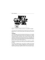
Worm
The worm and worm gear, illustrated in Figure 14.29, are used to transmit
motion and power when a high-ratio speed reduction is required. They
provide a steady quiet transmission of power between shafts at right angles.
The worm is always the driver and the worm gear the driven member. Like
helical gears, worms and worm gears have “hand.” The hand is determined
by the direction of the angle of the teeth. Thus, in order for a worm and
worm gear to mesh correctly, they must be the same hand.
300 Gears and Gearboxes
Figure 14.25 Typical set of helical gears
Helix
an
g
le
Figure 14.26 Illustrating the angle at which the teeth are cut
The most commonly used worms have either one, two, three, or four sep-
arate threads and are called single, double, triple, and quadruple thread
worms. The number of threads in a worm is determined by counting the
number of starts or entrances at the end of the worm. The thread of the
Gears and Gearboxes 301
Angle
Angle
Hub on
left side
Hub on
right side
Figure 14.27 Helix angle of the teeth the same regardless of side from
which the gear is viewed
Figure 14.28 Typical set of spiral gears
302 Gears and Gearboxes
Figure 14.29 Typical set of worm gears
worm is an important feature in worm design, as it is a major factor in worm
ratios. The ratio of a mating worm and worm gear is found by dividing the
number of teeth in the worm gear by the number of threads in the worm.
Herringbone
To overcome the disadvantage of the high end thrust present in helical gears,
the herringbone gear, illustrated in Figure 14.30, was developed. It consists
simply of two sets of gear teeth, one right-hand and one left-hand, on the
same gear. The gear teeth of both hands cause the thrust of one set to cancel
out the thrust of the other. Thus, the advantage of helical gears is obtained,
and quiet, smooth operation at higher speeds is possible. Obviously they
can only be used for transmitting power between parallel shafts.
Gear Dynamics and Failure Modes
Many machine trains utilize gear drive assemblies to connect the driver to
the primary machine. Gears and gearboxes typically have several vibration
spectra associated with normal operation. Characterization of a gearbox’s
Gears and Gearboxes 303
Figure 14.30 Herringbone gear
vibration signature box is difficult to acquire but is an invaluable tool for
diagnosing machine-train problems. The difficulty is that: (1) it is often
difficult to mount the transducer close to the individual gears and (2) the
number of vibration sources in a multigear drive results in a complex assort-
ment of gear mesh, modulation, and running frequencies. Severe drive-train
vibrations (gearbox) are usually due to resonance between a system’s nat-
ural frequency and the speed of some shaft. The resonant excitation arises
from, and is proportional to, gear inaccuracies that cause small periodic
fluctuations in pitch-line velocity. Complex machines usually have many
resonance zones within their operating speed range because each shaft can
excite a system resonance. At resonance these cyclic excitations may cause
large vibration amplitudes and stresses.
Basically, forcing torque arising from gear inaccuracies is small. However,
under resonant conditions torsional amplitude growth is restrained only
by damping in that mode of vibration. In typical gearboxes this damping is
often small and permits the gear-excited torque to generate large vibration
amplitudes under resonant conditions.
One other important fact about gear sets is that all gear-sets have a designed
preload and create an induced load (thrust) in normal operation. The direc-
tion, radial or axial, of the thrust load of typical gear-sets will provide some
304 Gears and Gearboxes
insight into the normal preload and induced loads associated with each type
of gear.
To implement a predictive maintenance program, a great deal of time should
be spent understanding the dynamics of gear/gearbox operation and the fre-
quencies typically associated with the gearbox. As a minimum, the following
should be identified.
Gears generate a unique dynamic profile that can be used to evaluate gear
condition. In addition, this profile can be used as a tool to evaluate the
operating dynamics of the gearbox and its related process system.
Gear Damage
All gear sets create a frequency component, called gear mesh. The funda-
mental gear mesh frequency is equal to the number of gear teeth times the
running speed of the shaft. In addition, all gear sets will create a series of
sidebands or modulations that will be visible on both sides of the primary
gear mesh frequency. In a normal gear set, each of the sidebands will be
spaced at exactly the 1X or running speed of the shaft and the profile of the
entire gear mesh will be symmetrical.
Normal Profile
In addition, the sidebands will always occur in pairs, one below and one
above the gear mesh frequency. The amplitude of each of these pairs will be
identical. For example, the sideband pair indicated, as −1 and +1 in Figure
14.31, will be spaced at exactly input speed and have the same amplitude.
If the gear mesh profile were split by drawing a vertical line through the
actual mesh, i.e., the number of teeth times the input shaft speed, the two
halves would be exactly identical. Any deviation from a symmetrical gear
Frequency
Gear mesh
Ϫ4 ϩ4
Ϫ3 ϩ3
Ϫ2 ϩ2
Ϫ1
ϩ1
Amplitude
Figure 14.31 Normal profile is symmetrical
Gears and Gearboxes 305
mesh profile is indicative of a gear problem. However, care must be exer-
cised to ensure that the problem is internal to the gears and induced by
outside influences. External misalignment, abnormal induced loads and a
variety of other outside influences will destroy the symmetry of the gear
mesh profile. For example, the single reduction gearbox used to trans-
mit power to the mold oscillator system on a continuous caster drives two
eccentrics. The eccentric rotation of these two cams is transmitted directly
into the gearbox and will create the appearance of eccentric meshing of the
gears. The spacing and amplitude of the gear mesh profile will be destroyed
by this abnormal induced load.
Excessive Wear
Figure 14.32 illustrates a typical gear profile with worn gears. Note that the
spacing between the sidebands becomes erratic and is no longer spaced at
the input shaft speed. The sidebands will tend to vary between the input
and output speeds but will not be evenly spaced.
In addition to gear tooth wear, center-to-center distance between shafts will
create an erratic spacing and amplitude. If the shafts are too close together,
the spacing will tend to be at input shaft speed, but the amplitude will drop
drastically. Because the gears are deeply meshed, i.e., below the normal
pitch line, the teeth will maintain contact through the entire mesh. This
loss of clearance will result in lower amplitudes but will exaggerate any
tooth profile defect that may be present.
If the shafts are too far apart, the teeth will mesh above the pitch line. This
type of meshing will increase the clearance between teeth and amplify the
19 Hz
16 Hz
20 Hz
1x
INPUT
FREQUENCY
AMPLITUDE
Figure 14.32 Wear or excessive clearance changes sideband spacing
306 Gears and Gearboxes
FREQUENCY
AMPLITUDE
Figure 14.33 A broken tooth will produce an asymmetrical sideband profile
energy of the actual gear mesh frequency and all of its sidebands. In addition,
the load bearing characteristics of the gear teeth will be greatly reduced.
Since the pressure is focused on the tip of each tooth, there is less cross-
section and strength in the teeth. The potential for tooth failure is increased
in direct proportion to the amount of excess clearance between shafts.
Cracked or Broken Tooth
Figure 14.33 illustrates the profile of a gear set with a broken tooth. As the
gear rotates, the space left by the chipped or broken tooth will increase the
mechanical clearance between the pinion and bullgear. The result will be a
low amplitude sideband that will occur to the left of the actual gear mesh
frequency. When the next, undamaged teeth mesh, the added clearance will
result in a higher energy impact.
The resultant sideband, to the right of the mesh frequency, will have
much higher amplitude. The paired sidebands will have nonsymmetrical
amplitude that represents this disproportional clearance and impact energy.
If the gear set develops problems, the amplitude of the gear mesh frequency
will increase, and the symmetry of the sidebands will change. The pat-
tern illustrated in Figure 14.34 is typical of a defective gear set. Note the
asymmetrical relationship of the sidebands.
Common Characteristics
You should have a clear understanding of the types of gears generally
utilized in today’s machinery, how they interact, and the forces they gen-
erate on a rotating shaft. There are two basic classifications of gear drives:
(1) shaft centers parallel, and (2) shaft centers not parallel. Within these two
classifications are several typical gear types.
Gears and Gearboxes 307
LOW SPEED SHAFT
ROTATIONAL FREQUENCY
HIGH SPEED
SHAFT ROTATIONAL
FREQUENCY
INTERMEDIATE
FREQUENCIES
SIDE BANDS
TWICE GEAR MESH
THREE TIMES
GEAR MESH
GEAR MESH FREQUENCY
Figure 14.34 Typical defective gear mesh signature
Shaft Centers Parallel
There are four basic gear types that are typically used in this classification.
All are mounted on parallel shafts and, unless an idler gear in also used, will
have opposite rotation between the drive and driven gear (if the drive gear
has a clockwise rotation, then the driven gear will have a counterclockwise
rotation). The gear sets commonly used in machinery include the following:
Spur Gears
The shafts are in the same plane and parallel. The teeth are cut straight and
parallel to the axis of the shaft rotation. No more than two sets of teeth
are in mesh at one time, so the load is transferred from one tooth to the
next tooth rapidly. Usually spur gears are used for moderate- to low-speed
applications. Rotation of spur gear sets is opposite unless one or more idler
gears are included in the gearbox. Typically, spur gear sets will generate a
radial load (preload) opposite the mesh on their shaft support bearings and
little or no axial load.
308 Gears and Gearboxes
Backlash is an important factor in proper spur gear installation. A certain
amount of backlash must be built into the gear drive allowing for tolerances
in concentricity and tooth form. Insufficient backlash will cause early failure
due to overloading.
As indicated in Figure 14.11, spur gears by design have a preload opposite
the mesh and generate an induced load, or tangential force, TF, in the
direction of rotation. This force can be calculated as:
TF =
126,000 ∗hp
D
p
∗ rpm
In addition, a spur gear will generate a Separating Force, S
TF
, that can be
calculated as:
S
TF
= TF ∗tan φ
Where:
TF = Tangential force
hp = Input horsepower to pinion or gear
D
p
= Pitch diameter of pinion or gear
rpm = Speed of pinion or gear
φ = Pinion or gear tooth pressure angle
Helical Gears
The shafts are in the same plane and parallel but the teeth are cut at an
angle to the centerline of the shafts. Helical teeth have an increased length
of contact, run more quietly and have a greater strength and capacity than
spur gears. Normally the angle created by a line through the center of the
tooth and a line parallel to the shaft axis is 45 degrees. However, other angles
may be found in machinery. Helical gears also have a preload by design; the
critical force to be considered, however, is the thrust load (axial) generated
in normal operation; see Figure 14.12.
TF =
126,000 ∗hp
D
p
∗ RPM
S
TF
=
TF ∗tan φ
cos λ
T
TF
= TF ∗tan λ