Industrial Machinery Repair Part Episode 2 Part 9 pptx
Bạn đang xem bản rút gọn của tài liệu. Xem và tải ngay bản đầy đủ của tài liệu tại đây (1.63 MB, 25 trang )
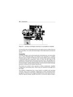
434 Steam Traps
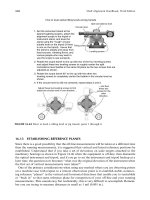
Figure 22.2 Float-and-thermostatic trap
it critical to select a trap that can handle the specific pressure, capacity, and
size requirements of the system.
The key advantage of float-and-thermostatic traps is their ability for quick
steam-system startup because they continuously purge the system of air and
other noncondensable gases. One disadvantage is the sensitivity of the float
ball to damage by hydraulic hammer.
Float-and-thermostatic traps are an economical solution for lighter conden-
sate loads and lower pressures. However, when the pressure and capacity
requirements increase, the physical size of the unit increases and its cost
rises. It also becomes more difficult to handle.
Thermodynamic or Disk-Type
Thermodynamic, or disk-type, steam traps use a flat disk that moves between
a cap and seat (see Figure 22.3). Upon startup, condensate flow raises the
disk and opens the discharge port. Steam, or very hot condensate entering
the trap, seats the disk. It remains seated, closing the discharge port, as
long as pressure is maintained above it. Heat radiates out through the cap,
thus diminishing the pressure over the disk, opening the trap to discharge
condensate.
Steam Traps 435
Cap
Disk
Figure 22.3 Thermodynamic steam trap
Wear and dirt are particular problems with a disk-type trap. Because of the
large, flat seating surfaces, any particulate contamination, such as dirt or
sand, will lodge between the disk and the valve seat. This prevents the valve
from sealing and permits live steam to flow through the discharge port. If
pressure is not maintained above the disk, the trap will cycle frequently.
This wastes steam and can cause the device to fail prematurely.
The key advantage of these traps is that one trap can handle a complete
range of pressures. In addition, they are relatively compact for the amount
of condensate they discharge. The chief disadvantage is difficulty in handling
air and other noncondensable gases.
Bimetallic
A bimetallic steam trap, which is shown in Figure 22.4, operates on the same
principle as a residential-heating thermostat. A bimetallic strip, or wafer,
connected to a valve disk bends or distorts when subjected to a change in
temperature. When properly calibrated, the disk closes tightly against a seat
when steam is present and opens when condensate, air, and other gases are
present.
Two key advantages of bimetallic traps are: (1) compact size relative to
their condensate load-handling capabilities, and (2) immunity to hydraulic-
hammer damage.
436 Steam Traps
Bimetal strip
Figure 22.4 Bimetal trap
Their biggest disadvantage is the need for constant adjustment or calibra-
tion, which is usually done at the factory for the intended steam operating
pressure. If the trap is used at a lower pressure, it may discharge live
steam. If used at a higher pressure, condensate may back up into the steam
system.
Thermostatic or Thermal Element
Thermostatic, or thermal-element, traps are thermally actuated using an
assembly constructed of high-strength, corrosion-resistant stainless steel
plates that are seam-welded together. Figure 22.5 shows this type of trap.
Upon startup, the thermal element is positioned to open the valve and purge
condensate, air, and other gases. As the system warms up, heat generates
pressure in the thermal element, causing it to expand and throttle the flow
of hot condensate through the discharge valve. The steam that follows the
hot condensate into the trap expands the thermal element with great force,
which causes the trap to close. Condensate that enters the trap during sys-
tem operation cools the element. As the thermal element cools, it lifts the
valve off the seat and allows condensate to discharge quickly.
Thermal elements can be designed to operate at any steam temperature. In
steam-tracing applications, it may be desirable to allow controlled amounts
of condensate to back up in the lines in order to extract more heat from
Steam Traps 437
Figure 22.5 Thermostatic trap
the condensate. In other applications, any hint of condensate in the system
is undesirable. The thermostatic trap can handle either of these conditions,
but the thermal element must be properly selected to accommodate the
specific temperature range of the application.
Thermostatic traps are compact, and a given trap operates over a wide
range of pressures and capacities. However, they are not recommended
for condensate loads over 15,000 pounds per hour.
Performance
When properly selected, installed, and maintained, steam traps are relatively
trouble-free and highly efficient. The critical factors that affect efficiency
include capacity and pressure ratings, steam quality, mechanical damage,
and calibration.
Capacity Rating
Each type and size of steam trap has a specified capacity for the amount of
condensate and noncompressible gas that it can handle. Care must be taken
to ensure that the proper steam trap is selected to meet the application’s
capacity needs.
438 Steam Traps
Pressure Rating
As discussed previously, each type of steam trap has a range of steam pres-
sures that it can effectively handle. Therefore, each application must be
carefully evaluated to determine the normal and maximum pressures that
will be generated by the steam system. Traps must be selected for the
worst-case scenario.
Steam Quality
Steam quality determines the amount of condensate to be handled by the
steam trap. In addition to an increased volume of condensate, poor steam
quality may increase the amount of particulate matter present in the con-
densate. High concentrations of solids directly affect the performance of
steam traps. If particulate matter is trapped between the purge valve and its
seat, the steam trap may not properly shut off the discharge port. This will
result in live steam being continuously exhausted through the trap.
Mechanical Damage
Inverted-bucket and float-type steam traps are highly susceptible to mechan-
ical damage. If the level arms or mechanical linkages are damaged or
distorted, the trap cannot operate properly. Regular inspection and main-
tenance of these types of traps are essential.
Calibration
Steam traps, such as the bimetallic type, must be periodically recalibrated
to ensure proper operation. All steam traps should be adjusted on a regular
schedule.
Installation
Installation of steam traps is relatively straightforward. As long as they are
properly sized, the only installation imperative is that they are plumb. If the
trap is tilted or cocked, the bucket, float, or thermal valve will not operate
properly. In addition, a nonplumb installation may prevent the condensate
chamber from fully discharging accumulated liquids.
Steam Traps 439
Table 22.1 Common failure modes of steam traps
THE PROBLEM
THE CAUSES
Trap will not discharge
Will not shut-off
Continuously blows steam
Capacity suddenly falls off
Condensate will not drain
Not enough steam heat
Traps freeze in winter
Back flow in return line
Back-pressure too high •
Boiler foaming or priming • •
Boiler gauge reads low •
Bypass open or leaking •
•
Condensate load greater than design
•
Condensate short-circuits
•
Defective thermostatic elements
•
Dirt or scale in trap
•
•
Discharge line has long horizontal runs •
Flashing in return main • •
High-pressure traps discharge into low-pressure
return
•
Incorrect fittings or connectors • •
Internal parts of trap broken or damaged • • • •
Internal parts of trap plugged • •
Kettles or other units increasing condensate load •
Leaky steam coils •
No cooling leg ahead of thermostatic trap • •
Open by-pass or vent in return line •
Pressure regulator out of order •
Process load greater than design •
Plugged return lines
•
Plugged strainer, valve, or fitting ahead of trap •
Scored or out-of-round valve seat in trap •
Steam pressure too high •
System is air-bound •
Trap and piping not insulated
•
Trap below return main • •
Trap blowing steam into return
•
Trap inlet pressure too low
• •
Trap too small for load
•
Source: Integrated Systems Inc.
440 Steam Traps
Operating Methods
Steam traps are designed for a relatively constant volume, pressure, and
condensate load. Operating practices should attempt to maintain these
parameters as much as possible. Actual operating practices are determined
by the process system, rather than the trap selected for a specific system.
The operator should periodically inspect them to ensure proper operation.
Special attention should be given to the drain line to ensure that the trap is
properly seated when not in the bleed or vent position.
Troubleshooting
A common failure mode of steam traps is failure of the sealing device (i.e.,
plunger, disk, or valve) to return to a leak-tight seat when in its normal
operating mode. Leakage during normal operation may lead to abnormal
operating costs or degradation of the process system. A single
3
4
steam trap
that fails to seat properly can increase operating costs by $40,000 to $50,000
per year. Traps that fail to seat properly or are constantly in an unload
position should be repaired or replaced as quickly as possible. Regular
inspection and adjustment programs should be included in the standard
operating procedures (SOPs).
Most of the failure modes that affect steam traps can be attributed to vari-
ations in operating parameters or improper maintenance. Table 22.1 lists
the more common causes of steam trap failures.
Operation outside the trap’s design envelope results in loss of efficiency
and may result in premature failure. In many cases, changes in the conden-
sate load, steam pressure or temperature, and other related parameters are
the root causes of poor performance or reliability problems. Careful atten-
tion should be given to the actual versus design system parameters. Such
deviations are often the root causes of problems under investigation.
Poor maintenance practices or the lack of a regular inspection program may
be the primary source of steam trap problems. It is important for steam
traps to be routinely inspected and repaired to assure proper operation.
23 V-Belt Drives
“Only Permanent Repairs Made Here”
V-belt drives are widely used in industry and commercial applications.
V-belts are utilized to transfer energy from a driver to the driven and usu-
ally transfer one speed ratio to another through the use of different sheave
sizes.
V-belts are constructed for three basic components, which vary from maker
to maker:
1 Load carrying section to transfer power.
2 Rubber compression section to expand sideways in the groove.
3 Cover of cotton or synthetic fiber to resist abrasion.
Understanding the construction of V-belts assists in the understanding of
belt maintenance. The standard V-belt must ride in the sheave properly. If
the belt is worn or the sheave is worn, then you will have slippage of the belt
and transfer of power, and speed will change resulting in a speed change
to a piece of equipment. If a V-belt drive is located near oil, grease, or
chemicals the V-belts could lose their capability through the deterioration
of the belt material, again resulting in the reduction of energy transfer and
quickly resulting in belt breakage or massive belt slippage.
Introduction
Belt drives are an important part of a conveyor system. They are used to
transmit needed power from the drive unit to a portion of the conveyor
system. This chapter will cover:
1 Various types of belts that are used to transmit power;
2 The advantages and disadvantage of using belt drives;
3 The correct installation procedure for belt drives;
442 V-Belt Drives
Driven
roll
Drive
motor
Figure 23.1 Belt drive
4 How to maintain belt drives;
5 How to calculate speeds and ratios that will enable you to make
corrections or adjustments to belt drive speeds;
6 How to determine belt length and sheave sizes when making speed
adjustments.
Belt Drives
Belt drives are used to transmit power between a drive unit and a driven
unit. For example, if we have an electric motor and a contact roll on a
conveyor, we need a way to transmit the power from the electric motor to
the roll. This can be done easily and efficiently with a belt drive unit. See
Figure 23.1.
Belt drives can consist of one or multiple belts, depending on the load that
the unit must transmit.
The belts need to be the matched with the sheave type, and they must be
tight enough to prevent slippage. Examples of the different belt and sheave
sizes are as follows:
1 Fractional horsepower V-belts: 2L, 3L, 4L, and 5L;
2 Conventional V-belts: A, B, A-B, C, D, and E;
Conventional cogged V-belts: AX, BX, and CX;
3 Narrow V-belts: 3V, 5V, and 8V;
Narrow cogged V-belts: 3VX and 5VX;
4 Power band belts: these use the same top width designations as the above
belts, but the number of bands is designated by the number preceding
V-Belt Drives 443
A
B
B
A
Figure 23.2 Examples of V-belts
the top width designation. For example, a 3-ribbed 5V belt would be
labeled 3/5V;
5 Positive-drive belts: XL, L, H, XH, and XXH.
The size of the belt must match the sheave size. If they do not match, then
the belt will not make proper contact with the sheave and will decrease the
amount of load it can transmit. They may look something like the illustration
in Figure 23.2.
Usually a set of numbers will follow the belt designation. These numbers
represent the actual length of the belt in inches. On conventional belts, the
length is given for the inside length of the belt, and on narrow belts it is
given for the outside length. An example of this would be a 5V750 belt;
the size of the belt gives it the 5V and the outside length of 75.0" gives it
the 750.
More information about the specific belt dimensions can be found in the
Goodyear Power Transmission Belt Drives manual.
Belt Selection
V-Belts
V-belts are best suited for transmitting light loads between short range
sheaves. They are excellent at absorbing shock. When an overload
occurs, they will act as an overload device and slip, thereby protecting
444 V-Belt Drives
Figure 23.3 Standard V-belt
Figure 23.4 Cogged belt
valuable equipment. They are also much quieter than other power trans-
mission devices such as chains.
Because of their design, they are easier to install and maintain than other
belt types. Other than an occasional retensioning, V-belts are virtually main-
tenance free. When properly installed and maintained, V-belts will provide
years of trouble-free operation. For an example, see Figure 23.3.
Cogged Belts
Cogged belts provide even longer life than conventional V-belts. Because
of their design, they run cooler than conventional belts, thereby increasing
the overall life of the belt. For an example, see Figure 23.4.
Joined Belts
Joined or power band belts provide a good alternative in pulsating drives
where standard V-belts have a tendency to turn over. They function like a
V-Belt Drives 445
Figure 23.5 Joined belt (VX type)
Figure 23.6 Positive drive belt
standard V-belt, with the exception that they are joined by the top fabric of
the belt. These belts can be used with the standard V-belt sheaves, making
selection and installation easy. For an example, see Figure 23.5.
Positive-Drive Belts
Positive-drive belts are sometimes called timing belts because they are often
used in operations when timing a piece of equipment is critical. However,
they are also used in applications where heavy loads cause standard V-belts
to slip. They are flexible and provide the same benefit as standard V-belts,
but their alignment is more critical. For an example, see Figure 23.6.
Sheaves
Sheaves are wheels with a grooved rim on which the belt rides. Sheaves
are manufactured in various widths and diameters. Some have spokes, and
some do not. For an example, see Figure 23.7.
Sheaves are made of cast steel for heavy-duty applications. For lighter appli-
cations, they are forged out of steel plate. Cast-iron sheaves are always used
in applications where fluctuating loads are present. They provide a flywheel
effect that minimizes the effects of fluctuating loads.
446 V-Belt Drives
Figure 23.7 Positive drive belt
When they are mounted to a shaft, sheaves should be straight and have little
or no wobble. For drives where the belt enters the sheave at an angle, deep-
groove sheaves are available. These are especially useful when the belts must
turn or twist.
Deep-groove sheaves can be used anywhere belt stability is a problem. In
some cases, one drive shaft drives more than one driven shaft. When this
occurs, more than one sheave can be mounted on one shaft. This is nec-
essary only when sheaves of more than one size are needed. If the drive
sheaves are the same size, one multibelt sheave can be used.
Most sheaves are balanced and capable of belt speeds of 6,000 feet per
minute or less. If you note excessive vibration during operation or excessive
bearing wear, you may need to balance or replace the sheaves.
Power Train Formulas
Shaft Speed
The size of the sheaves in a belt drive system determines the speed relation-
ship between the drive and driven sheaves. For example, if the drive sheave
has the same size sheave as the driven, then the speed will be equal. See
Figure 23.8.
If we change the size of the driven sheave, then the speed of the shaft will
also change. We know what the speed is of the electric motor and the size
V-Belt Drives 447
6"
6"
Driven Drive
1800
rpm
1800
rpm
Figure 23.8 Shaft speed
12" 6"
Driven Drive
1800
rpmrpm
Figure 23.9 Belt drive speed ratio
of the sheaves, and now we can calculate the speed of the driven shaft by
using the following formula (see Figure 23.9):
Driven shaft rpm =
Drive sheave diameter in inches × drive shaft rpm
Driven sheave diameter
Driven shaft rpm =
6 × 1800
12
900 =
6 × 1800
12
Now we understand how changing the size of a sheave will also change the
shaft speed. Knowing this, we could also assume that to change the shaft
rpm we must change the sheave size. The problem is, how do we know the
exact size sheave that we need in order to reach the desired speed? Use the
448 V-Belt Drives
6" 6"
Driven Drive
1800
rpm
1800
rpm
Figure 23.10 Speed ratio
same formula that was used to calculate shaft speed, only switch the location
of the driven shaft speed and the driven sheave diameter.
Driven shaft rpm =
Drive sheave diameter in inches × drive shaft rpm
Driven sheave diameter
Let’s change the problem to look like this:
Driven sheave
diameter
=
Drive sheave diameter in inches × drive shaft rpm
Driven shaft rpm
Let’s say that we have a problem similar to the ones that we just did, but we
want to change the shaft speed of the driven unit. If we know the speed we
are looking for, we can use the formula above to calculate the sheave size
required. See Figure 23.10
Let’s change the speed of the driven shaft to 900 rpm (see Figure 23.11):
Driven shaft rpm =
6 × 1800
900
12 =
6 × 1800
900
Belt Length
Many times when a mechanic has to change out belts, the numbers on the
belts cannot be read. So what should be done? Take a tape measure and
wrap it around the sheaves to get the belt length? This is not a very accurate
V-Belt Drives 449
___ 6"
Driven Drive
1800
r
p
m
900
r
p
m
Figure 23.11 Speed ratio calculation
way to determine the length. So, usually the mechanic ends up taking a
number of different size belts hoping to have a size that will fit.
Instead, take a couple of measurements, then use a simple formula to cal-
culate the actual length that is needed. First, move the sheaves together
until they are as close as the adjustments will allow. Then move the motor
or drive out
1
4
of its travel. Now you are ready to take the measurements.
The following information is needed for an equation to find belt length (see
Figure 23.12):
1 Diameter of the drive sheave.
2 Diameter of the driven sheave.
3 Center-to-center distance between the shafts.
Now use the following formula to solve the equation:
Belt length =
drive diameter × 3.14
2
+
driven diameter × 3.14
2
+ center to center × 2
Use the formula above to find the belt length.
Belt length =
6" × 3.14
2
+
12" × 3.14
2
+ 35" × 2
98.26" or 98" =
6" × 3.14
2
+
12" × 3.14
2
+ 35" × 2
450 V-Belt Drives
12" 6"
Driven Drive
35"
Figure 23.12 Belt length example
Multiple Sheaves
When calculating multiple sheave systems, think of each set of sheaves as a
two-sheave system. Try to solve the following problem by only calculating
two sheaves at a time.
Belt Speed
In order to calculate the speed of a belt in feet per minute (FPM), the
following information is needed:
1 The diameter of the sheave that the belt is riding on.
2 The shaft rpm of the sheave.
With this information, we can use the following formula:
FPM =
diameter × 3.14 × rpm
12
Use this formula to find the speed of the following belt (see Figure 23.13):
FPM =
diameter × 3.14 × rpm
12
2826 =
6" × 3. 14 × 1800
1"
V-Belt Drives 451
12" 6"
Driven Drive
1800
rpm
900
rpm
Figure 23.13 Belt speed calculation
Figure 23.14 Belt maintenance
Belt Maintenance
Routine maintenance is essential if a belt drive is to operate properly. Belt
maintenance should include regular checks of belt alignment and tension.
You should also perform frequent inspections of the sheaves and shafts.
Routine maintenance will extend the life of the sheaves and belts. Belt-drive
maintenance requires little time, but it must be done regularly. Keeping the
belts clean and free of oil and grease will help ensure long belt life. See
Figure 23.14.
When you replace a belt, always check the tension immediately after
installation. Check it again after 24 hours of operation.
452 V-Belt Drives
Never force a V-belt onto a sheave. There have been a number of injuries to
fingers and hands as a result of this.
The belt should never ride in the bottom of the sheave. The sheave is deeper
than the belt. The belt is made to ride near the top of the sheave. The belt
may wear to the point that it is riding on the bottom of the sheave. If so, it
will slip no matter how much tension is applied to the belt.
Keep used belt sets together for use on multibelt drives.
Routine preventive maintenance is essential if a belt drive is to operate
properly. Belt maintenance should include regular checks of belt condition,
belt alignment, and tension. You should also perform frequent inspections
of the sheaves and shafts.
You may need to replace belts that are worn or damaged from overheating
or contact with oil or grease. Never replace one belt of a multibelt drive.
Belts stretch with use. If you replace one belt of a multibelt drive, it will be
tighter than the others. See Figure 23.15.
A belt that is tighter than the others in a set will pull all the load. Store the
old belts as a set. You may be able to use part of the set on a drive requiring
fewer belts.
Figure 23.15 Belt tensioning
V-Belt Drives 453
Figure 23.16 Belt tension gauges
Sheave and Belt Installation
Proper tools must be selected. (These must be identified on your PM
inspection checklist or job plan.)
In addition to a set of basic hand tools, you will also need a reliable ten-
sion gauge with a set of belt tension tables, a set of sheave gauges, and a
straightedge or string with a flashlight. See Figures 23.16 and 23.17.
When the proper procedures are followed for installing V-belts, they will
yield years of trouble-free service.
Shaft and Sheave Alignment
1 The shafts must be parallel or the life of the belt will be shortened. The
first step is to level the shafts; this is done by placing a level on each of the
shafts. Then shim the low side until the shaft is level. See Figure 23.18.
454 V-Belt Drives
Figure 23.17 Sheave inspection gauges
Figure 23.18 Shaft alignment
V-Belt Drives 455
25" 25"
Figure 23.19 Sheave alignment
2 Next, make sure the shafts are parallel. This is done by measuring at
different points on the shaft and adjusting the shafts until they are an
equal distance apart. Make sure that the shafts are pulled in as close
as possible before performing this procedure. Then you can use the
jacking bolts to move the shafts apart evenly after the belt is installed.
See Figure 23.19.
WARNING: Before installing a set of used sheaves, verify the size and condi-
tion of the sheaves with a sheave gauge. Select the proper gauge for the size
of sheave. For example, if you have a 5V sheave that measures 14.4", use the
40-deg. gauge. Insert the gauge into the sheave groove; if you can see light
on either side, the sheave is worn. Sheave gauges are also useful when the
size of the sheave cannot be found stamped on it. See Figure 23.20.
3 Install the sheaves on the shafts following the manufacturer’s recom-
mendations. Locate and install the first sheave, then use a straightedge
or a string to line the other one up with the one previously installed.
See Figure 23.21.
Belt Installation
Install the belt on the sheaves. Never force a belt on with a screwdriver.
This can damage the belt and could cause you to lose a finger. Next, begin
increasing the distance between the sheaves by turning the jacking bolts;
do this until the belt is snug but not tight. Using a belt tension gauge,
456 V-Belt Drives
5V
10.01–16.0
O.D.
40 deg
Over 16.0
O.D.
42 deg
Under 10.0
O.D.
38 deg
Figure 23.20 Sheave gauge
Figure 23.21 Final alignment
V-Belt Drives 457
35"
50 100 150
Figure 23.22 Belt tensioning
tighten the belts to the manufacturer’s recommendation. Be sure to measure
deflection and tension. This information can be found in a belt tension
gauge’s information sheet. See Figure 23.22.
Check for parallel and angular alignment of sheaves. The tolerance for align-
ment of V-belts is to within
1
10
" per foot of span, and for positive-drive belts
to within
1
16
of an inch per foot of span.
When you replace a belt, always check the tension immediately after
installation. Check the tension again after 24 hours of operation.
The belt should never ride in the bottom of the sheave because the sheave
is deeper than the belt. The belt is made to ride near the top of the sheave.
The belt may wear to the point that it is riding on the bottom of the sheave. If
so, it will slip no matter how much tension is applied to the belt.
Belt Storage
Sometimes belts are stored on shelves in their original packaging. Other
times they are stacked without packaging. If possible, store them on two
or more pegs to prevent distortion. Keep belts away from damp floors and
high heat areas.
458 V-Belt Drives
You may need to replace belts that are worn or damaged from overheating
or contact with oil or grease. Never replace one belt of a multibelt drive.
Belts stretch with use. If you replace one belt of a multibelt drive, it will be
tighter than the others and thus not meet the horsepower requirements the
drive was designed for.
Preventive Maintenance Procedures
Inspection (failure risks for not following the procedures below are noted
along with a rating): LOW: minimal risk/low chance of failure; MEDIUM:
failure is possible, and equipment not operating to specifications is highly
probable; HIGH: failure will happen prematurely.
●
Check belt tension using a belt tension gauge. Measure the deflection and
tension for the size of the belt. (Be sure to write tension and deflection
specifications for the mechanic on the PM checklist.) Set tension on belt
if deficiency noted.
Risk if the procedure is not followed: MEDIUM. Belt slippage will occur, thus
resulting in equipment not operating to operation specifications. Another
result from slippage is for belts to break, and the consequences could be a
fire or at least machine stoppage.
●
Identify any type of oil, grease, or chemical within 36 inches of belts (oil
leakage from gearbox, motor, bearing, or chemicals from other sources).
Write a corrective maintenance work order to repair leak or eliminate
source of oil, grease, or chemical from the area.
Risk if the procedure is not followed: HIGH. Belt slippage will occur, thus
resulting in equipment not operating to operation specifications. Another
result for slippage is for belts to break, and the consequences could be a
fire or at least machine stoppage.
●
Check sheave alignment. If sheaves are not in alignment, align to manufac-
turer’s specification. (Be sure to write the specification on this procedure;
mechanics should not guess on this specification.)
Risk if the procedure is not followed: MEDIUM. Rapid belt wear will occur,
thus resulting in equipment not operating to specifications. The belts could
break if cords in the belt, begin to break due to this misalignment.