Machine Design Databook Episode 2 part 2 doc
Bạn đang xem bản rút gọn của tài liệu. Xem và tải ngay bản đầy đủ của tài liệu tại đây (885.5 KB, 40 trang )
REFERENCES
1. Lingaiah, K., and B. R. Narayana Iyengar, Machine Design Data Handbook, Engineering College
Cooperative, Bangalore, India, 1962.
2. Lingaiah, K., and B. R. Narayana Iyengar, Machine Design Data Handbook, Vol. I (SI Units and Customary
Metric Units), Suma Publishers, Bangalore, India, 1986.
3. Lingaiah, K., Machine Design Data Handbook, Vol. II (SI Units and Customary Metric Units), Suma
Publishers, Bangalore, India, 1986.
4. Soderberg, C. R., ‘‘Working Stresses,’’ J. Appl. Mechanics, Vol. 57, p. A-106, 1935.
5. ASME Code for Design of Transmission Shafting, Standard ANS/ASME B106.1M, 1985.
6. Shigley, J. E., Machine Design, McGraw-Hill Publishing Company, New York, 1956.
7. Kececioglu, D. B., and V. R. Lalli, Reliability Approach to Rotating Component Design, Technical Note
TND-7846, NASA, 1975
8. Davies, V. C., H. T. Gough, and H. V. Pollard, Discussion to the Strength of Metals under Combined
Alternating stresses, Proc of the Inst. Mech. Eng., 131(3), pp. 66–69, 1935.
9. Loewenthal, S. H., Proposed Design Procedure for Transmission Shafting under Fatigue Loading, Technical
Note TM-7802, NASA, 1978.
10. Gough, H. J., and H. V. Pollard, The Strength of Metals under Combined Alternating stresses, Proc of the
Inst. Mech. Eng., 131(3), pp. 3–103, 1935.
BIBLIOGRAPHY
Berchard, H. A., ‘‘A Comprehensive Method for Designing Shafts to Insure Fatigue Life,’’ Machine Design, April
25, 1963.
Black, P. H., and O. Eugene Adams, Jr., Machine Design, McGraw-Hill Publishing Company, New York, 1983.
British Standards Institution.
Deutschman, A. D., W. J. Michels, and C. E. Wilson, Machine Design—Theory and Practice, Macmillan
Publishing Company, New York, 1975.
Maleev, V. L., and J. B. Hartman, Machine Design, International Textbook Company, Scranton, Pennsylvania,
1954.
Marks’ Standard Handbook for Mechanical Engineers, 8th ed., McGraw-Hill Publishing Company, New York,
1978.
Vallance, A., and V. L. Doughtie, Design of Machine Members, McGraw-Hill Publishing Company, New York,
1951.
DESIGN OF SHAFTS 14.17
Downloaded from Digital Engineering Library @ McGraw-Hill (www.digitalengineeringlibrary.com)
Copyright © 2004 The McGraw-Hill Companies. All rights reserved.
Any use is subject to the Terms of Use as given at the website.
DESIGN OF SHAFTS
TABLE 14-1
Empirical shafting formulas
Load factors considered Power capacity, P
Kind of service Torsion, K
t
Bending, K
b
kW hp
Transmission shafts in torsion only 1.0 1.0 54,831D
3
n
0
1:225 Â 10
À6
D
3
n
Line shafting with limited bending 1.0 1.5 34,532D
3
n
0
7:715 Â 10
À7
D
3
n
Head or main shafts with heavy bending loads 1.0 2.5 20,715D
3
n
0
4:628 Â 10
À7
D
3
n
TABLE 14-2
Shock and endurance factors
Nature of loading K
b
K
t
Stationary shafts
Gradually applied load 1.0 1.0
Suddenly applied load 1.5–2.0 1.5–2.0
Rotating shafts
Steady or gradually applied loads 1.5 1.0
Suddenly applied loads, minor 1.5–2.0 1.0–1.5
shocks only
Suddenly applied loads, heavy 2.0–3.0 1.5–3.0
shocks
TABLE 14-3
Values of constant c
Allowable
Coefficient stress
c in
Type of shaft loading Eq. (14-61) MPa kpsi
Shaft heavily loaded, subjected 0.82 17 2.5
to shock, or reversed under
full load
Line shafts and countershafts, 1.1 27 4.0
loaded in bending but not
reversed
Line shafts or bar with pulleys 1.56 44 6.4
close to the bearings
TABLE 14-4
Shock load factors
a
for use in Eq. (14-81)
Nature of load K
sb
, K
st
Gradually applied load 1.00
Loads applied with minor shocks 1.0–1.5
Loads applied with heavy shocks 1.5–2.0
a
Data from Berchard, H. A., ‘‘A Comprehensive Method for
Designing Shafts to Insure Fatigue Life,’’ Machine Design, April 25,
1963.
14.18 CHAPTER FOURTEEN
Downloaded from Digital Engineering Library @ McGraw-Hill (www.digitalengineeringlibrary.com)
Copyright © 2004 The McGraw-Hill Companies. All rights reserved.
Any use is subject to the Terms of Use as given at the website.
DESIGN OF SHAFTS
TABLE 14-5
Spacing
a
for fine shaft bearings
Transmission shaft stressed in torsion only, mm
Line shaft carrying pulleys or gears and
subjected to usual bending loads, mm
Diameter of shaft, mm 1–250 rpm 251–400 rpm 1–250 rpm 251–400 rpm
36.5 274.5 244.0 213.5 198.0
49.0 305.0 274.5 229.0 213.5
62.0 335.5 305.0 244.0 228.5
74.5 366.0 335.5 259.0 244.0
87.5 396.0 366.0 274.5 259.0
100.0 427.0 396.0 289.5 274.5
112.5 457.0 427.0 305.0 289.5
a
Center-to-center distance in millimeters.
TABLE 14-6
Sizes of shafts
Diameters, mm (in)
4 (0.16) 12 (0.48) 40 (1.6) 75 (3.0) 110 (4.4) 180 (7.2)
5 (0.20) 15 (0.60) 45 (1.8) 80 (3.2) 120 (4.8) 190 (7.6)
6 (0.24) 17 (0.68) 50 (2.0) 85 (3.4) 130 (5.2) 200 (8.0)
7 (0.28) 20 (0.80) 55 (2.2) 90 (3.6) 140 (5.6) 220 (8.8)
8 (0.32) 25 (1.0) 60 (2.4) 95 (3.8) 150 (6.0) 240 (9.6)
9 (0.36) 30 (1.2) 65 (2.6) 100 (4.0) 160 (6.4) 260 (10.4)
10 (0.4) 35 (1.4) 70 (2.8) 105 (4.2) 170 (6.8) 280 (11.2)
TABLE 14-7
Load factors for various machines, k
l
a
Driver Driven machinery Factor, k
l
Steam turbine Electric generator, steady load; turbine blower 1.00
Electric generator, uneven load; centrifugal pump 1.25
Induced-draft fan; line shaft; gear drive 1.50
Rolling mill, gear drive 2.00
Electric motor Turbine blower; metalworking machinery 1.25
Centrifugal pump; wood working machinery 1.50
Line shaft; ship propeller; double acting pump 1.75
Triplex single-acting pump; elevator; crane 1.75
Compressor, air or ammonia 1.75
Rolling mill; rubber mill 2.50
Steam engine Values for electric-motor drive multiplied by 1.2–1.5
Gas and oil engines Values for electric-motor drive multiplied by 1.3–1.6 the factor depending on the
coefficient of steadiness of the flywheel
a
To be used also in Eqs. (5–9) and (19–79).
DESIGN OF SHAFTS 14.19
Downloaded from Digital Engineering Library @ McGraw-Hill (www.digitalengineeringlibrary.com)
Copyright © 2004 The McGraw-Hill Companies. All rights reserved.
Any use is subject to the Terms of Use as given at the website.
DESIGN OF SHAFTS
CHAPTER
15
FLYWHEELS
SYMBOLS
1,2
a major axis of ellipse, m (in)
negative acceleration or deceleration, m/s
2
(ft/s
2
)
A cross-sectional area of the rim, m
2
(in
2
)
b minor axis of ellipse, m (in)
width of rim, m (in)
C
f
coefficient of fluctuation of rotation
d diameter of shaft, m (in)
d
h
hub diameter, m (in)
D flywheel diameter, m (in)
D
o
outside diameter of rim, m (in)
E excess energy, J (ft lbf)
F
c
centrifugal force, kN (lbf )
F
0
c
centrifugal force per unit width of rim, kN (lbf)
g acceleration due to gravity, 9.8066 m/s
2
(32.2 ft/s
2
)
h depth of rim, m (in)
i number of arms
k
o
polar radius of gyration of the rim, m (in)
I mass moment of inertia, N s
2
m (lbf s
2
ft)
J polar second moment of inertia, m
4
(in
4
)
k
t
torsional stiffness of shaft, N m/rad (lbf in/rad)
M
tm
mean torque, N m (lbf ft)
M
t
transmitted torque, N m (lbf ft)
m coefficient of steadiness
n mean speed, rpm
n
1
maximum speed, rpm
n
2
minimum speed, rpm
r mean radius of the flywheel, m (in)
t time, s
T
1
tension in belt on tight side, kN (lbf )
T
2
tension in belt on slack side, kN (lbf)
v mean rim velocity, m/s (ft/min)
v
1
maximum rim velocity, m/s (ft/min)
v
2
minimum rim velocity, m/s (ft/min)
W rim weight, kN (lbf )
specific weight of material or weight density, N/m
3
(lbf/in
3
)
Z sectional modulus of the arm cross section at the hub, m
3
(in
3
)
15.1
Downloaded from Digital Engineering Library @ McGraw-Hill (www.digitalengineeringlibrary.com)
Copyright © 2004 The McGraw-Hill Companies. All rights reserved.
Any use is subject to the Terms of Use as given at the website.
Source: MACHINE DESIGN DATABOOK
stress (also with subscripts), MPa (psi)
1
,
2
maximum and minimum angular displacement of flywheel from
constant speed deviation, rad (deg)
! average angular speed, rad/s
!
1
, !
2
maximum and minimum angular speed, respectively, rad/s
The equation of motion of ith rotor of I
i
inertia in a
multirotor system connected by (i À 1) number of
shafts of various inertias subjected to external torque
The equation of motion of a flywheel, which is
mounted on a shaft between two supports and rotates
with an angular velocity and subjected to an input
external torque M
ti
KINETIC ENERGY
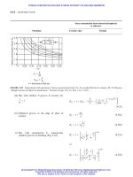
Kinetic energy (Fig. 15-1)
For variation of torque with crank angle for two-
cylinder engine
FIGURE 15-1 Torque-crank shaft angle curve for a two-cylinder engine.
The kinetic energy of flywheel at an angular displace-
ment
1
and at angular velocity !
1
during one cycle
The kinetic energy of flywheel at an angular displace-
ment
2
and at angular velocity !
2
The change in kinetic energy or energy fluctuation
due to change in angular velocity !
1
to !
2
in one cycle
I
i
i
¼ M
ti
À M
tði À1Þ
ð15-1Þ
I ¼ M
ti
À M
to
¼ k
t
ð
2
À
1
Þð15-2Þ
where
M
to
¼ output torque, N m (lbf ft)
¼ angular displacement of flywheel, rad (deg)
K ¼
1
2
mv
2
¼
Wv
2
2g
¼
1
2
I!
2
ð15-3Þ
Refer to Fig. 15-1.
K
1
¼
1
2
I!
2
1
¼
Wv
2
1
2g
ð15-4Þ
K
2
¼
1
2
I!
2
2
¼
Wv
2
2
2g
ð15-5Þ
E ¼ K
2
À K
1
¼
1
2
Ið!
2
2
À !
2
1
Þ¼
Wðv
2
2
À v
2
1
Þ
2g
¼
1
2
Ið!
2
À !
1
Þð!
2
þ !
1
Þ
¼ Ið!
2
À !
1
Þ! ¼ Wðv
2
À v
1
Þ
v
g
ð15-6Þ
Particular Formula
15.2 CHAPTER FIFTEEN
Downloaded from Digital Engineering Library @ McGraw-Hill (www.digitalengineeringlibrary.com)
Copyright © 2004 The McGraw-Hill Companies. All rights reserved.
Any use is subject to the Terms of Use as given at the website.
FLYWHEELS
The coefficient of fluctuation of speed or rotation
The change in kinetic energy or excess energy
FLYWHEEL EFFECT OR POLAR
MOMENT OF INERTIA
The mean angular velocity
The coefficient of steadiness
STRESSES IN RIM (Figs. 15-2 and 15-3)
The component of the centrifugal force normal to any
diameter of the flywheel
The tangential force due to hoop stress in the flywheel
rim (Fig. 15-3)
The tensile stress created in each cross section of the
rim by the centrifugal force
The centrifugal force per unit width of rim (Fig. 15-3)
C
f
¼
!
2
À !
1
!
¼
v
2
À v
1
v
¼
n
2
À n
1
n
ð15-7Þ
E ¼ K
2
À K
1
¼ I!
2
C
f
¼
Wv
2
C
f
g
ð15-8Þ
Wk
2
¼
182:40gE
n
2
1
À n
2
2
ð15-9Þ
! ¼
!
2
þ !
1
2
ð15-10Þ
m ¼
1
C
f
ð15-11Þ
Refer to table 15-1 for C
f
.
F
c
¼
2bhr
2
!
2
g
ð15-12Þ
F
¼
bhr
2
!
2
g
ð15-13Þ
¼ 0:01095
g
r
2
n
2
SI ð15-14Þ
F
0
c
¼ 0:01095
r
2
n
2
h
g
SI ð15-15Þ
Particular Formula
TABLE 15-1
Coefficient of fluctuation of rotation, C
f
Driven machine Type of drive C
f
AC generators, single or parallel Direct-coupled 0.01
AC generators, single or parallel Belt 0.0167
DC generators, single or parallel Direct-coupled 0.0143
DC generators, single or parallel Belt 0.029
Spinning machinery Belt 0.02–0.015
Compressure, pumps Gears 0.02
Paper, textiles, and flour mills Belt 0.025–0.02
Woodworking and metalworking machinery Belt 0.0333
Shears and pumps Flexible coupling 0.05–0.04
Concrete mixers, excavators, and compressors Belt 0.143–0.1
Crushers, hammers, and punch presses Belt 0.2
FLYWHEELS
15.3
Downloaded from Digital Engineering Library @ McGraw-Hill (www.digitalengineeringlibrary.com)
Copyright © 2004 The McGraw-Hill Companies. All rights reserved.
Any use is subject to the Terms of Use as given at the website.
FLYWHEELS
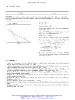
The bending stress
The combined tensile stress
STRESSES IN ARMS (Fig. 15-2)
The stresses in the arm
FIGURE 15-2 Flywheel.
When the flywheel is used as a belt pulley, the stresses
at the hub
In case of thin-rim flywheel, the stress
Stress due to centrifugal force
The maximum tensile stress in an arm is at hub
The force necessary to stop the flywheel
RIM DIMENSIONS (Fig. 15-2)
The relation between k
o
in cm and the outside
diameter D of the rim in m
Cross-sectional area of the rim
b
¼ 0:2146
r
3
n
2
ghi
2
SI ð15-16Þ
R
¼ 0:75 þ 0:25
b
ð15-17Þ
1
¼
M
t
ðD Àd
h
Þ
iZD
ð15-18Þ
FIGURE 15-3 Centrifugal force acting on the rim of a
flywheel.
2
¼
ðT
1
À T
2
ÞðD Àd
h
Þ
2iZ
ð15-19Þ
0
2
¼
ðT
1
À T
2
ÞðD Àd
h
Þ
iZ
ð15-20Þ
3
¼ 0:01095
r
2
n
2
g
SI ð15-21Þ
max
¼
1
þ
2
þ
3
ð15-22Þ
F ¼
Wa
g
ð15-23Þ
k
2
o
¼ 0:125½D
2
o
þðD
o
À 2hÞ
2
ð15-24Þ
A ¼
W
2k
ð15-25Þ
Particular Formula
15.4 CHAPTER FIFTEEN
Downloaded from Digital Engineering Library @ McGraw-Hill (www.digitalengineeringlibrary.com)
Copyright © 2004 The McGraw-Hill Companies. All rights reserved.
Any use is subject to the Terms of Use as given at the website.
FLYWHEELS
The relation between depth and width of rim
The outside diameter of rim
The hub diameter in m
The hub length
ARMS (Fig. 15-2)
The major axis in case of elliptical section can be
computed from the relation
REFERENCES
1. Lingaiah, K., and B. R. Narayana Iyengar, Machine Design Data Handbook, Vol. I (SI and Customary Metric
Units), Suma Publishers, Bangalore, India, 1986.
2. Lingaiah, K., Machine Design Data Handbook (SI and U.S. Customary Units), McGraw-Hill Publishing
Company, New York, 1994.
b
h
¼ 0:65 to 2 ð15-26Þ
D
o
¼ 2k
o
þ h ðapprox:Þð15-27Þ
d
h
¼ 1:75d þ6:35 Â 10
À3
¼ 2d ð15-28Þ
l ¼ 2d to 2:5d ð15-29Þ
a ¼
3
ffiffiffiffiffiffiffiffiffi
64Z
r
ð15-30Þ
where z ¼
ba
2
32
and a ¼ 2b ð15-31Þ
Particular Formula
FLYWHEELS
15.5
Downloaded from Digital Engineering Library @ McGraw-Hill (www.digitalengineeringlibrary.com)
Copyright © 2004 The McGraw-Hill Companies. All rights reserved.
Any use is subject to the Terms of Use as given at the website.
FLYWHEELS
CHAPTER
16
PACKINGS AND SEALS
SYMBOLS
1;2
A area of seal in contact with the sliding member, m
2
(in
2
)
A
g
gasket area over which the bolt loads are distributed, m
2
(in
2
)
A
1
, A
2
area of cross section of unthreaded and threaded portions of
bolt, m
2
(in
2
)
b width of U-collar, m (in)
gland width or depth of groove, m (in)
c radial clearance between rod and the bushing,
radial deflection of the ring, m (in)
d nominal diameter of the bolt, m (in)
diameter of sliding member, m (in)
d
1
outside diameter of packing material, m (mm)
outside diameter of seal ring (Fig. 16-3), m (in)
d
2
minor diameter of bolt, m (in)
d
a
actual diameter of wire, m (in)
d
i
inside diameter of packing material, m (in)
D
m
estimated mean diameter of conical spring, m (in)
D
am
actual mean diameter of conical spring, m (in)
E modulus of elasticity, GPa (psi)
F
b
bolt load, kN (lbf )
F
frictional force, kN (lbf )
F
o
frictional force of the stuffing box when there is no fluid
pressure, kN (lbf)
g acceleration due to gravity, 9.8066 m/s
2
(9806.6 mm/s
2
)
(32.2 ft/s
2
)
h radial ring wall thickness, m (in)
h
i
uncompressed gasket thickness, m (in)
h
loss of head, m/m (in/in)
i number of bolts
l depth of U-collar (Fig. 16-2a), m (in)
l
1
, l
2
length of joint, m (in)
(dl) incremental length in the direction of velocity [Eq. (16-15)],
m (in)
bolt elongation [Eq. (16-24)], m (in)
M
t
twisting moment, N m (lbf in)
M
ti
initial bolt torque, N m (lbf in)
16.1
Downloaded from Digital Engineering Library @ McGraw-Hill (www.digitalengineeringlibrary.com)
Copyright © 2004 The McGraw-Hill Companies. All rights reserved.
Any use is subject to the Terms of Use as given at the website.
Source: MACHINE DESIGN DATABOOK
p fluid pressure, MPa (psi)
p
f
flange pressure on the gasket, MPa (psi)
P
s
minimum per cent compression to seal
(dp) pressure differential in the direction of velocity [Eq. (16-15)],
MPa (psi)
Q discharge, m
3
/s (cm
3
/s, mm
3
/s) (in
3
/s)
r equivalent radius, m (in)
v velocity, m/s (ft/min)
w nominal packing cross section, m (in)
y deflection of spring, m (in)
absolute viscosity of fluid, Pa s (cP)
d
design stress, MPa (psi)
coefficient of friction
ELASTIC PACKING
1–3
Frictional force exerted by a soft packing on the
reciprocating rod
FRICTION
Friction resistance
Torsional resistance in a rotary motion friction
METALLIC GASKETS (Fig. 16-1)
The empirical relations
3
F
¼ kpd ð16-1Þ
where k ¼ 0:005 and p ¼ 0:343 MPa SI
k ¼ 0:2 and p ¼ 50 psi USCS
F
¼ F
o
þ Ap ð16-2Þ
where ¼ 0:01 for rubber and soft lubricated
leather
¼ 0:15 for hard leather
M
t
¼
F
d
2
¼
kd
2
p
2
ð16-3Þ
where k ¼ 0:005 SI
k ¼ 0:2 USCS
c ¼ 0:2d þ 5mmif d 100 mm ð16-4Þ
c ¼ 0:08
ffiffiffi
d
p
if d > 0:1mm SI ð16-5aÞ
c ¼ 0:5
ffiffiffi
d
p
if d > 4 USCS ð16-5bÞ
h ¼
d
8
þ 12:54 mm or 0:5in ð16-6Þ
a ¼ d þ 2c ð16-7Þ
¼ 108 to 158 ð16-8Þ
d
2
¼ 0:2ðd þ0:102Þ=
ffiffi
i
p
SI ð16-9aÞ
d
2
¼ 0:2ðd þ4Þ=
ffiffi
i
p
USCS ð16-9bÞ
Particular Formula
16.2 CHAPTER SIXTEEN
Downloaded from Digital Engineering Library @ McGraw-Hill (www.digitalengineeringlibrary.com)
Copyright © 2004 The McGraw-Hill Companies. All rights reserved.
Any use is subject to the Terms of Use as given at the website.
PACKINGS AND SEALS
Diameter of bolt is also found by equating the work-
ing strength of the bolts to the pressure p exerted by
the fluid on the gland and the frictional force F
SELF-SEALING PACKING (Fig. 16-2)
Houghton, Welch, and Jenkin’s formula for an
approximate thickness of a U-shaped collar for
great pressure
3
FIGURE 16-2 U-collar.
Width
Depth
d
2
¼
ffiffiffiffiffiffiffiffiffiffiffiffiffiffiffiffiffiffiffiffiffiffi
ðd
2
1
À d
2
Þp
i
d
s
þ
4F
i
d
ð16-10Þ
where
d
2
¼ minor diameter of bolt, m (in)
d
¼ 68:7 to 83.3 MPa (10 to 12 kpsi)
h ¼ 6:36 Â 10
À3
d
0:2
SI ð16-11aÞ
where h and d in m
h ¼ 1:6d
0:2
SI ð16-11bÞ
where h and d in mm
h ¼ 0:12d
0:2
USCS ð16-11cÞ
where d and d in in
b ¼ 4h ð16-12aÞ
l ¼ 1:2b to 1:8b ð16-12bÞ
Particular Formula
FIGURE 16-1 Stuffing box with bolted gland. (V. L. Maleev and J. B. Hartman, Machine Design, International Textbook Com-
pany, Scranton, Pennsylvania, 1954.)
PACKINGS AND SEALS
16.3
Downloaded from Digital Engineering Library @ McGraw-Hill (www.digitalengineeringlibrary.com)
Copyright © 2004 The McGraw-Hill Companies. All rights reserved.
Any use is subject to the Terms of Use as given at the website.
PACKINGS AND SEALS
PACKINGLESS SEALS
Leakage of the fluid past a rod can be computed with
fair accuracy by the formula
STRAIGHT-CUT SEALINGS (Fig. 16-3a)
The equation for loss of liquid head
Leakage velocity
Quantity of leakage
Stress in a seal ring
For allowable temperatures for materials and surface
treatment
FIGURE 16-3(a) Straight-cut seal.
Q ¼
c
3
12
ð p
1
À p
2
Þ
d
l
SI ð16-13aÞ
Q ¼ 1:79ð100cÞ
3
ð p
1
À p
2
Þd
l
USCS ð16-13bÞ
Refer to Table 16-1 for values of .
h
¼ 64v=2gd
2
1
ð16-14Þ
v ¼
ðdpÞr
2
8ðdlÞ
ð16-15Þ
Q ¼ vA ð16-16Þ
¼
0:4815cE
h
d
1
h
À 1
2
ð16-17Þ
Refer to Table 16-2.
Particular Formula
TABLE 16-1
Absolute viscosities
Temperature Absolute viscosity, Temperature Absolute viscosity,
Fluid K 8C MPa s cP K 8C MPa s cP
Steam 293 20 0.0097 0.0097 539 266 0.018 0.018
Air 293 20 0.018 0.018 366 93 0.022 0.022
Water 273 0 1.79 1.79 311 38 0.69 0.69
Water 293 20 1.0 1.0 333 60 0.40 0.40
Gasoline 293 20 0.6 0.6 355 82 0.30 0.30
Kerosene 293 20 2.7 2.7 355 82 1.30 1.30
Fuel oil, 308 Baume
´
293 20 5.0 5.0 355 82 1.60 1.60
Fuel oil, 248 Baume
´
293 20 40 40 355 82 4 4
Spindle oil 293 20 20–35 20–35 355 82 3–4 3–4
Machine oil 293 20 200–500 200–500 372 99 1.5–16 5.5–16
Castor oil 293 20 1000 1000 316 43 200 200
16.4 CHAPTER SIXTEEN
Downloaded from Digital Engineering Library @ McGraw-Hill (www.digitalengineeringlibrary.com)
Copyright © 2004 The McGraw-Hill Companies. All rights reserved.
Any use is subject to the Terms of Use as given at the website.
PACKINGS AND SEALS
V-RING PACKING
Single-spring installations
The estimated mean diameter of conical spring
The wire size (Table 16-3)
The actual mean diameter of conical spring
The deflection of spring
Multiple-spring installations
BOLTS AND STRESSES IN FLANGE JOINTS
The bolt load in gasket joint
The flange pressure developed due to tightening of
bolts that hold the gasket joint mechanical assembly
together
The load on the bolt when it is tightened
STRESSES IN GROOVED JOINTS
The uncompressed gasket thickness that will provide
the minimum sealing compression when the flanges
are tightened into face-to-face contact
D
m
¼ d
i
þ
3w
2
ð16-18Þ
d ¼
D
2
m
139300
1=3
SI ð16-19aÞ
where d and D
m
in m
d ¼
D
2
m
3535
1=3
USCS ð16-19bÞ
where d and D
m
in in
d ¼
D
2
m
193:3
1=3
Customary Metric ð16-19cÞ
where d and D
m
in mm
D
am
¼ d
1
À
1
2
ðw þd
a
Þð16-20Þ
y ¼
0:0123D
2
am
d
a
ð16-21Þ
Two standard cylindrical spring sizes are generally
used, depending on packing size.
F
b
¼
11m
ti
d
ð16-22Þ
p
f
¼
iF
b
A
g
C
u
¼
2iM
t
A
g
C
u
d
b
ð16-23Þ
where C
u
¼ torque friction coefficient
F
b
¼
EðdlÞ
ðl
1
=A
1
Þþðl
2
=A
2
Þ
ð16-24Þ
h
i
¼
100b
100 ÀP
s
ð16-25Þ
Particular Formula
PACKINGS AND SEALS
16.5
Downloaded from Digital Engineering Library @ McGraw-Hill (www.digitalengineeringlibrary.com)
Copyright © 2004 The McGraw-Hill Companies. All rights reserved.
Any use is subject to the Terms of Use as given at the website.
PACKINGS AND SEALS
BOLT LOADS IN GASKET JOINT
ACCORDING TO ASME BOILER AND
PRESSURE VESSEL CODE (Fig. 16-3b)
4
FIGURE 16-3(b) Location of gasket load reaction.
The required bolt load under operating condition
sufficient to contain the hydrostatic end force and
simultaneously to maintain adequate compression
on the gasket to ensure seating
The required initial bolt load to seat the gasket joint-
contact surface properly at atmospheric temperature
condition without internal pressure
Total required cross-sectional area of bolts at the root
of thread
Total cross-sectional area of bolt at root of thread or
section of least diameter under stress required for the
operating condition
Total cross-sectional area of bolt at root of thread or
section of least diameter under stress required for
gasket seating
The actual cross-sectional area of bolts using the root
diameter of thread or least diameter of unthreaded
portion (if less), to prevent damage to the gasket
during bolting-up
W
m1
¼ H þ H
P
¼ð=4G
2
PÞþ2bGmP ð16-26Þ
W
m2
¼ bGy ð16-27Þ
Refer to Tables 8-20 and 8-21 for gasket factor m and
minimum design seating stress, y, b, and b
o
A
m
> A
m1
or A
m2
ð16-28Þ
A
m1
¼
W
m1
sbd
ð16-29Þ
Refer to Table 8-17 for
sbd
A
m2
¼
W
m2
sbat
ð16-30Þ
A
b
¼
2yGN
sbat
j< A
m
ð16-31Þ
Particular Formula
16.6 CHAPTER SIXTEEN
Downloaded from Digital Engineering Library @ McGraw-Hill (www.digitalengineeringlibrary.com)
Copyright © 2004 The McGraw-Hill Companies. All rights reserved.
Any use is subject to the Terms of Use as given at the website.
PACKINGS AND SEALS
FLANGE DESIGN BOLT LOAD W
The bolt load in the design of flange for operating
condition
The bolt load in the design of flange for gasket seating
The relation between bolt load per bolt (W
b
),
diameter of bolt (D) and torque (M
t
)
(Note: The meanings of symbols given in Eqs. (16-26)
to (16-37) are defined in Chap. 8.)
For location of gasket load reaction due to tightening
of flange bolts
The total load on bolts in the gasket joint according to
Whalen
5
The load on bolts, which is based on hydrostatic end
force
For more information on design data, selection of
packing and seals, properties of sealants and packing
materials, dimensions and tolerances of seals, and
chamfers on shaft, operating temperatures of various
types of seals, data for metallic o-rings, q-rings and o-
ring gaskets, static and dynamic seals, lip seals, and
safety factors, etc.
W ¼ W
m1
ð16-32Þ
W ¼
A
m
þ A
b
2
sbat
ð16-33Þ
W
b
¼ 0:17DM
t
for lubricated bolts USCS ð16-34Þ
where W
b
in lbf, D in in, M
t
in lbf in
W
b
¼ 263:5DM
t
SI ð16-35Þ
where W
b
in N, D in m, M
t
in N m
W
b
¼ 0:2DM
t
for unlubricated bolts
USCS ð16-36Þ
where W
b
in lbf, D in in, M
t
in lbf in
W
b
¼ 310DM
t
SI ð16-37Þ
where W
b
in N, D in m, M
t
in N m
Refer to Fig. 16-3b
F
b
¼
g
A
g
ð16-38Þ
where
A
g
¼ contact area of gasket, m
2
(in
2
)
g
¼ gasket seating stress, MPa (psi), taken from
Table 16-35
F
b
¼ nP
t
A
m
ð16-39Þ
where
P
t
¼ test pressure or internal pressure if no test pres-
sure is available, MPa (psi)
A
m
¼ hydrostatic area (based on mean diameter of
gasket) on which internal pressure acts, m
2
(in
2
)
n ¼ factor of safety taken from Table 16-36
Refer to Tables 16-4 to 16-36
Particular Formula
PACKINGS AND SEALS
16.7
Downloaded from Digital Engineering Library @ McGraw-Hill (www.digitalengineeringlibrary.com)
Copyright © 2004 The McGraw-Hill Companies. All rights reserved.
Any use is subject to the Terms of Use as given at the website.
PACKINGS AND SEALS
Leakage through bush seals (Fig. 16-3c):
The oil flow (Q) through plain axial bush seal due to
leakage under laminar flow condition, Fig. 16-3c,
panel a
The volumetric flow rate per unit pressure per unit
periphery (q) under laminar flow condition for axial
bush seal, Fig. 16-3c, panel a
The oil flow (Q) through plain radial bush seal due to
leakage under laminar flow condition, Fig. 16-3c,
panel b
The volumetric flow rate per unit pressure per unit
periphery (q) under laminar flow condition for
radial bush seal, Fig. 16-3c, panel b
Q ¼
2aðP
s
À P
a
Þ
l
q ð16-40Þ
where Q in m
3
/s (in
3
/s)
¼ absolute viscosity, Pa s (cP)
The symbols used in Eqs. (16-40) to (16-45) have the
meaning as defined in Fig. 6-13c, panels a and b.
q ¼
c
3
12
ð1 þ1:5"
2
Þ
a
ð16-14Þ
for incompressible fluid
where
" ¼
c
q ¼
c
3
24
P
s
þ P
a
P
a
ð16-42Þ
for compressible fluid
b
Q ¼
2aðP
s
À P
a
Þ
a Àb
q ð16-43Þ
q ¼
c
3
12
a Àb
a log
e
a
b
ð16-44Þ
for incompressible fluid
q ¼
c
3
24
a Àb
a
P
s
þ P
a
P
a
ð16-45Þ
for compressible fluid
Particular Formula
FIGURE 16-3(c) Plain bush seals. (Panels a and b courtesy of J. M. Neale, Tribology Handbook, Butterworths, London, 1973.)
a
If shaft rotates, onset of Taylor vortices limits validity of formula to ðV
c
=Þ
ffiffiffiffiffiffiffi
c=a
p
< 41:3 (where ¼ kinematic viscosity).
b
For Mach number <1.0, i.e., fluid velocity < local velocity of sound.
16.8 CHAPTER SIXTEEN
Downloaded from Digital Engineering Library @ McGraw-Hill (www.digitalengineeringlibrary.com)
Copyright © 2004 The McGraw-Hill Companies. All rights reserved.
Any use is subject to the Terms of Use as given at the website.
PACKINGS AND SEALS
The radial pressure distribution for laminar flow
condition between smooth parallel surfaces in case
face seal
The amount of leakage of fluid through face seal
The theoretical equation for zero leakage of fluid
through face seal
The power loss or consumed due to leakage of fluid
through face seal
The shape factor (S
pf
) for a circular or annular gasket
which is the ratio of the area of one load face to the
area free to bulge
6
For further design and selection of various types of
seals, packings and gaskets, etc.
For nomenclature of gasketed joint
For packing assembly for a mechanical piston rod
For shape factor for various gasket materials
6
For power absorption and starting torque for un-
balanced and balanced seals
p Àp
1
¼
3!
2
20g
ðr
2
À R
2
1
ÞÀ
6v
h
3
ln
r
R
ð16-46Þ
where
p ¼pressure at radial position r, MPa (lbf/in
2
)
p
1
¼pressure at seal inside radius, MPa (psi)
p
2
¼internal hydraulic pressure MPa (lbf/in
2
)
r ¼radial position, m (in)
¼kinematic viscosity N s/m
2
(lbf s/in
2
)
¼fluid density, lb/in
3
(kg/mm
3
)
! ¼rotational speed, rad/s
R
1
¼inside radius of rotating member, m (in)
R
2
¼outside radius of rotating member, m (in)
h ¼thickness of fluid between members, m (in)
Q ¼
h
3
6 lnðR
2
=R
1
Þ
3!
2
20g
ðR
2
2
À R
2
1
ÞÀp
2
À p
1
Þ
ð16-47Þ
where Q ¼ volumetric leakage rate of fluid, m
3
/s
(in
3
/s)
p
2
À p
1
¼
3
20
!
2
ðR
2
2
À R
2
1
Þð16-48Þ
P ¼
w
2
13200h
ðR
4
2
À r
4
1
Þð16-49Þ
where P ¼ power loss, hp
S
pf
¼
D
o
À D
i
4h
ð16-50Þ
where D
o
¼ outside diameter of gasket, m (in)
D
i
¼ inside diameter of gasket, m (in)
Refer to Figs. 16-4 to 16-14.
Refer to Fig. 16-15.
Refer to Fig. 16-16.
Refer to Fig. 16-17.
Refer to Fig. 16-18.
Particular Formula
PACKINGS AND SEALS
16.9
Downloaded from Digital Engineering Library @ McGraw-Hill (www.digitalengineeringlibrary.com)
Copyright © 2004 The McGraw-Hill Companies. All rights reserved.
Any use is subject to the Terms of Use as given at the website.
PACKINGS AND SEALS
FIGURE 16-4 Single radial lip seal.
FIGURE 16-5 Exclusion seal.
FIGURE 16-6 Radial exclusion seal. (Produced from ‘‘Packings and Seals’’ Issue, Machine Design, Jan. 20, 1977.)
FIGURE 16-7 Two-piece rod seal. (Produced from ‘‘Pack-
ings and Seals’’ Issue, Machine Design, Jan. 20, 1977.)
FIGURE 16-8 Clearance seal idealized labyrinth.
FIGURE 16-9 Face seal.
FIGURE 16-10 Compression packing.
16.10 CHAPTER SIXTEEN
Downloaded from Digital Engineering Library @ McGraw-Hill (www.digitalengineeringlibrary.com)
Copyright © 2004 The McGraw-Hill Companies. All rights reserved.
Any use is subject to the Terms of Use as given at the website.
PACKINGS AND SEALS
TABLE 16-2
Allowable temperatures for materials and surface treatments
Temperature Temperature
Material or surface treatment 8F 8C Material or surface treatment 8F 8C
Material
Low-alloy gray irons 650 343 Carbon (high-temperature) 950 510
Malleable iron 720 382 K-30 (filled teflons) 450–500 232–260
Ductile iron 720 382 S-Monel 950 510
Ni-Resist 800 427 Polymide 750 399
Ductile Ni-Resist 1000 538 Surface treatment
410 Stainless Steel 900 482 Chromium plate 500 260
17-4 PH Stainless Steel 900 482 Tin plate 720 382
Bronze 500 260 Silver plate 600 315.5
Stellite no. 31 1200 649 Cadmium nickel plate 1000 538
Inconel X 1200 649 Flame plate LW1 1000 538
Tool steel, Rc 62–65 900 482 Flame plate LC-1A 1600 871
Flame plate LA-2 1600 871
TABLE 16-3
Standard wire sizes for V-packing expanders
Wire gauge
a
Wire diameter, mm Wire gauge Wire diameter, mm Wire gauge Wire diameter, mm
19 1.04 13 2.31
5
32
3.82
18 1.20 12 2.67 8 4.11
17 1.37 11 2.05 7 4.49
16 1.57
1
8
3.17
3
16
4.77
15 1.83 10 3.31 6 4.89
14 2.03 9 3.60 5 5.25
a
American Wire Gauge (AWG).
TABLE 16-4
Dimensions (in mm) for chamfer on the shaft for mounting the seals
d
1
d
1
d
1
d
1
d
1
d
1
h11 d
3
h11 d
3
h11 d
3
h11 d
3
h11 d
3
h11 d
3
6 4.8 24 21.5 52 48.3 85 80.4 160 153 340 329
7 5.7 25 22.5 55 51.3 90 85.3 170 163 360 349
8 6.6 26 23.4 56 52.3 95 90.1 180 173 380 369
9 7.5 28 25.3 58 54.2 100 95.0 190 183 400 389
10 8.4 30 27.3 60 56.1 105 99.9 200 193 420 409
11 9.3 32 29.2 62 58.1 110 104.7 210 203 440 429
12 10.2 35 32.0 63 59.1 115 109.6 220 213 460 449
14 12.1 36 33.0 65 61.0 120 114.5 230 223 480 469
15 13.1 38 34.9 68 63.9 125 119.4 240 233 500 489
16 14.0 40 36.8 70 65.8 130 124.3 250 243
17 14.9 42 38.7 72 67.7 135 129.2 260 252
18 15.1 45 41.6 75 70.7 140 133.0 280 269
20 17.7 48 44.5 78 73.6 146 138.0 300 289
22 19.6 50 46.4 80 75.5 150 143.0 320 309
16.11
Downloaded from Digital Engineering Library @ McGraw-Hill (www.digitalengineeringlibrary.com)
Copyright © 2004 The McGraw-Hill Companies. All rights reserved.
Any use is subject to the Terms of Use as given at the website.
PACKINGS AND SEALS
TABLE 16-5
Selection of guide for packing materials
Leather (natural and
Condition synthetic) Homogeneous Fabricated
Oil Good Good Good
Air Good Good Good
Water Good Good Good
Steam Not recommended Good Good
Solvents Not recommended Good Good
Acids Not recommended Good Good
Alkalis Not recommended Good Fair
Temperature range À558C þ828C
a
À558C þ2008C
a
À408C þ2608C
a
Types of metal Ferrous and nonferrous Chrome-plated steel and
nonferrous alloys with hard,
smooth surfaces
Chrome-plated steel and
nonferrous alloys with hard,
smooth surfaces
Metal finish, rms (max.) 63 16 32
Clearances Medium Very close Close
Extrusions or cold flow Good Poor Fair
Friction coefficient Low Medium and high Medium
Resistance to abrasion Good Fair Fair
Maximum pressure, MPa
(kpsi)
861.7 (125) 343.4 (50) 549.4 (80)
Concentricity Medium Very close Close
Side loads Fair Poor Fair
High shock loads Good Poor to fair Fair
a
Depending on specification or combination of materials.
FIGURE 16-11 Molded packing. Typical U-ring packing.
FIGURE 16-12 Diaphragm seals-rolling diaphragm.
16.12 CHAPTER SIXTEEN
Downloaded from Digital Engineering Library @ McGraw-Hill (www.digitalengineeringlibrary.com)
Copyright © 2004 The McGraw-Hill Companies. All rights reserved.
Any use is subject to the Terms of Use as given at the website.
PACKINGS AND SEALS
TABLE 16-6
Types of seals and their uses
Type Uses
Radial lip seals For retaining lubricants in equipments having rotating, reciprocating oscillating
shafts, to exclude foreign matter
Single lip (Fig. 16-4) For containing highly viscous materials at low speeds
Single lip—spring-loaded For containing lubricants of lower viscosity at higher speeds in clean atmosphere
Double lip with one lip spring-loaded For excluding contaminants such as dust and dirt
Dual lip with both lips spring-loaded For containing lubricant on one side and for excluding fluid on the other
Split seal For splash system of lubrication
External seal For fixed shaft and rotating bore
Hydrodynamic seal For directing oil flow back into the area to be sealed
Exclusion seals (Figs. 16-5 and 16-6)
Wipers, scrapers, axial seals, bellows,
and boots
To prevent entry of foreign materials into moving parts of machinery—to avoid
contamination of lubricants
Clearance seals (Fig. 16-8)
Labyrinths, bushing, and ring seals Dynamic seals-to prevent leakage from a high-pressure station at one end of
bushing to a region of low-pressure station at the other end of bushing
Ring seals—split ring seals To seal reciprocating components
Expanding split ring Used in compressors, pumps, and internal-combustion engines
Contracting split ring Linear actuators where high-pressure, high-temperature radiation and fatigue are
expected
Straight-cut seal ring (Fig. 16-3a) Piston seal for low-grade actuators
Step seal ring Devices where free-passage leakage is not permissible
Circumferential seal For rotary applications with low leakage and high performance
Face seals (Fig. 16-9)
Stationary, rotating, and metal
bellows type
Running seal between two flat precision finished surfaces, for high-speed
applications, stuffing boxes, and temperature applications
Compression packing (Fig. 16-10) For the throat of a stuffing box and its gland, dynamic seal
Molded packing (Fig. 16-11) For automatic-hydraulic or mechanical packings
Lip type
Single and multiple spring-loaded
packings
For sealing reciprocating parts
Squeeze type Fitted in rectangular grooves machined in hydraulic or pneumatic mechanisms and
used as a piston seal in hydraulic actuating cylinder, valve seat, or valve stem
packing
Felt radial type Used at high speeds from 10 to 20 m/s
Diaphragm seals (Fig. 16-12) To prevent interchange of a fluid or contaminant between two separated areas,
dynamic sealing and force transmitter
Nonmetallic gaskets (Fig. 16-13) Static sealing
Metallic gaskets (Table 16-7)
Corrugated, metal-jacketed, plain or
machined (flat metal) round, heavy,
or light cross-section (solid metal)
Static sealing, for high pressures and severe conditions, cast iron flanges, ammonia
fittings, hydraulic cylinders, gas mains, heat exchangers, boiler openings, vacuum
and cryogenic lines, and valve bonnets
Sealants
Hardening (rigid or flexible),
non-hardening and tapes
To exclude dust, dirt, moisture, and chemicals or contain a liquid or gas-surface
coatings to protect against mechanical or chemical attack, to exclude noise, to
improve appearance and to perform a joining function, thermal insulating,
vibration damping
PACKINGS AND SEALS
16.13
Downloaded from Digital Engineering Library @ McGraw-Hill (www.digitalengineeringlibrary.com)
Copyright © 2004 The McGraw-Hill Companies. All rights reserved.
Any use is subject to the Terms of Use as given at the website.
PACKINGS AND SEALS
TABLE 16-7
Properties and uses of nonmetallic gasket materials
Classification Special characteristics General uses
Rubber asbestos Tough and durable, relatively incompressible,
good steam and hot water resistance
Heavy duty bolted and threaded joints as in water
and steam pipe fittings; temperatures up to
2608C
Cork and rubber Provides fluid barrier and resilience with
compressibility; does not extrude from joint; die
cuts well; high coefficient of friction
General-purpose gasketing; enables design of
metal-to-metal joints; high friction keeps gasket
positioned even where closing pressure is not
perpendicular to flange faces
Cork composition General purpose material compressible; high
friction, low cost; excellent oil and solvent
resistance; poor resistance to alkalis and
corrosive acids
Mating rough or irregular parts; oil sealing at low
cost in normal range of temperatures and
pressures
Rubber, plastics Highly adjustable according to compounding,
hardness, modulus, fabric reinforcement, etc.;
generally impervious, not compressible
Installations involving stretching over projections
or where flow of gasket into threads or recesses
is desired; for lowest compression set and
maximum resistance to fluids such as alkalis, hot
water, and certain acids
Paper
Untreated Low cost, noncorrosive Spacers, dust barriers, splash seals where
breathing and wicking not objectionable
Treated General-purpose material; good oil, gasoline and
water resistance
Machined or reasonably uniform flanges where
adequate bolt pressures can be applied
Combination
constructions
Innumerable modifications available, depending
on materials used and methods of combining
Usually employed for extreme conditions and
special purposes
16.14 CHAPTER SIXTEEN
Downloaded from Digital Engineering Library @ McGraw-Hill (www.digitalengineeringlibrary.com)
Copyright © 2004 The McGraw-Hill Companies. All rights reserved.
Any use is subject to the Terms of Use as given at the website.
PACKINGS AND SEALS
TABLE 16-8
Minimum metallic gasket seating stress
Minimum seating stress
a
Type Material Thickness, mm MPa kpsi
Aluminum 3 109.8 16.0
1.5 and 0.75 137.3 20.0
Copper 3 248.1 36.0
1.5 and 0.75 309.9 45.0
f
Soft steel (iron) 3 379.0 55.0
1.5 and 0.75 474.1 69.0
Monel 3 448.2 65.0
1.5 and 0.75 559.9 81.0
Stainless steel 3 577.3 84.0
1.5 and 0.75 646.2 94.0
Aluminum 3
b
172.1 25.0
1.5
b
206.9 30.0
0.75
b
241.2 35.0
Copper 3
b
241.2 35.0
1.5
b
275.6 40.0
0.75
b
309.9 45.0
f
Soft steel (iron) 3
b
379.0 55.0
1.5
b
413.8 60.0
0.75
b
448.2 65.0
Monel 3
b
448.2 65.0
1.5
b
482.5 70.0
0.75
b
557.6 80.0
Stainless steel 3
b
517.3 75.0
1.5
b
557.6 80.0
0.75
b
655.1 95.0
Aluminum 3 10.3 1.5
Copper 3 13.7 2.0
f
Soft steel (iron) 3 27.4 4.0
Monel 3 30.9 4.5
Stainless steel 3 41.2 6.0
Aluminum 3 13.7 2.0
Copper 3 17.2 2.5
f
Soft steel (iron) 3 20.6 3.0
Monel 3 24.0 3.5
Soft steel 3 27.4 4.0
Lead 3 3.4 0.5
Aluminum 3 6.9 1.0
Copper 3 17.1 2.5
f
Soft steel (iron) 3 24.0 3.5
Monel 3 30.9 4.5
Stainless steel 3 41.2 6.0
Inconel 3 51.5 7.5
Hastelloy c 3 68.6 10.0
a
Seating stress values shown do not apply to ASME Code. Also they are based on optimum surface finish and clean flange surface, i.e., no grease,
oil or gasket compound.
b
Figures indicated are pitch, and the values of stress apply for all thicknesses.
PACKINGS AND SEALS 16.15
Downloaded from Digital Engineering Library @ McGraw-Hill (www.digitalengineeringlibrary.com)
Copyright © 2004 The McGraw-Hill Companies. All rights reserved.
Any use is subject to the Terms of Use as given at the website.
PACKINGS AND SEALS
TABLE 16-9
Compression packing for various service conditions
Service condition
Fluid medium Reciprocating shafts Rotating shafts Piston or cylinders Valve stems
Acids and caustics Asbestos, metallic,
plastic (pliable),
semimetallic, TFE
fluorocarbon resins and
yarns
Asbestos, plastic
(pliable), semimetallic,
TFE fluorocarbon
resins and yarns
TFE fluorocarbon
resins
Asbestos, plastic
(pliable), semimetallic
TFE fluorocarbon
resins and yarns
Air, gas Asbestos, metallic,
semimetallic
Asbestos, semimetallic Leather, metallic Asbestos, semimetallic
Ammonia, low-pressure
steam
Duck and rubber,
metallic, semimetallic
Asbestos, semimetallic Duck and rubber Asbestos, duck and
rubber, semimetallic
Cold and hot gasoline
and oils
Asbestos, plastic
(pliable), semimetallic
Asbestos, plastic
(pliable), semimetallic
Asbestos, plastic
(pliable), semimetallic
High-pressure steam Asbestos, metallic,
plastic (pliable),
semimetallic
Asbestos, metallic,
plastic (pliable),
semimetallic
Metallic Asbestos, metallic,
plastic (pliable),
semimetallic
Cold and hot water Duck and rubber,
leather, plastic (pliable),
semimetallic
Asbestos, plastic
(pliable), semimetallic
Duck and rubber Asbestos, duck and
rubber, plastic (pliable),
semimetallic
FIGURE 16-13 Common types of gasketed joints.
16.16 CHAPTER SIXTEEN
Downloaded from Digital Engineering Library @ McGraw-Hill (www.digitalengineeringlibrary.com)
Copyright © 2004 The McGraw-Hill Companies. All rights reserved.
Any use is subject to the Terms of Use as given at the website.
PACKINGS AND SEALS
TABLE 16-10
Dimensions of oil seals
Nominal
a
b Æ 0:2, mm Nominal
a
b Æ 0:2, mm
Shaft bore diameter Shaft bore diameter
diameter d
1
, of housing, Types Ac
b
min, diameter d
1
, of housing, Types Ac
b
min,
mm mm and B Type C mm mm mm and B Type C mm
616 7 0.3
22
716 7 0.3
22
816 7 0.3
22
24
922 7 0.3
24
26
10 19 7 0.3
22
24
26
11 22 7 0.3
26
12 22 7 0.3
24
28
30
14 24 7 0.3
28
30
35
15 24 7 0.3
26
30
32
35
16 28 7 0.3
30
32
35
17 28 7 0.3
30
32
35
40
18 30 7 0.3
32
35
40
20 30 7 0.3
32
35
40
47
22 32 7 — 0.3
35 9
40
47
24 35 7 — 0.3
37 9
40
47
25 35 7 — 0.4
40 9
42
47
52
26 37 7 — 0.4
42 9
47
28 40 7 — 0.4
47 9
52
30 40 7 — 0.4
42 9
47
52
62
32 45 7 — 0.4
47
52 9
16.17
Downloaded from Digital Engineering Library @ McGraw-Hill (www.digitalengineeringlibrary.com)
Copyright © 2004 The McGraw-Hill Companies. All rights reserved.
Any use is subject to the Terms of Use as given at the website.
PACKINGS AND SEALS