Machine Design Databook Episode 2 part 3 ppt
Bạn đang xem bản rút gọn của tài liệu. Xem và tải ngay bản đầy đủ của tài liệu tại đây (1.04 MB, 40 trang )
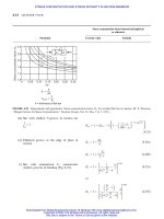
FIGURE 16-18 Power absorption and starting torque for
balanced and unbalanced seals. (M. J. Neale, Tribology Handbook,
Butterworths, London, 1973.)
PACKINGS AND SEALS
16.33
Downloaded from Digital Engineering Library @ McGraw-Hill (www.digitalengineeringlibrary.com)
Copyright © 2004 The McGraw-Hill Companies. All rights reserved.
Any use is subject to the Terms of Use as given at the website.
PACKINGS AND SEALS
REFERENCES
1. Lingaiah, K., and B. R. Narayana Iyengar, Machine Design Data Handbook,Vol. I(SI and Customary Units),
Suma Publishers, Bangalore, India, 1986.
2. Lingaiah, K., Machine Design Data Handbook, Vol. II (SI and Customary Metric Units), Suma Publishers,
Bangalore, India, 1986.
3. Maleev, V. L., and J. B. Hartman, Machine Design, International Textbook Company, Scranton,
Pennsylvania, 1954.
4. The American Society of Mechanical Engineers, ASME Boilers and Pressure Vessel Code, Section VIII,
Division I, 1986.
5. Whalen, J. J., ‘‘How to Select the Right Gasket Material,’’ Product Engineering, Oct. 1860.
6. Shigley, J. E., and C. R. Mischke, Standard Handbook of Machine Design, McGraw-Hill Book Company,
1986.
7. Neale, M. J., Tribology Handbook, Butterworths, London, 1975.
8. Ratelle, W. J., ‘‘Seal Selection, Beyond Standard Practice,’’ Machine Design, Jan. 20, 1977.
9. ‘‘Packings and Seals’’ Issue, Machine Design, Jan. 1977.
10. Faires, V. M., Design of Machine Elements, Macmillan Book Company, 1955.
11. Bureau of Indian Standards.
12. Rothbart, H. A., Mechanical Design and Systems Handbook, McGraw-Hill Book Company, New York, 1985.
13. Lingaiah, K., Machine Design Data Handbook, McGraw-Hill Book Company, New York, 1994.
16.34 CHAPTER SIXTEEN
Downloaded from Digital Engineering Library @ McGraw-Hill (www.digitalengineeringlibrary.com)
Copyright © 2004 The McGraw-Hill Companies. All rights reserved.
Any use is subject to the Terms of Use as given at the website.
PACKINGS AND SEALS
CHAPTER
17
KEYS, PINS, COTTERS, AND JOINTS
SYMBOLS
4;5;6
a addendum for a flat root involute spline profile, m (in)
A area, m
2
(in
2
)
b breadth of key, m (in)
effective length of knuckle pin, m (in)
dedendum for a flat root involute spline profile, m (in)
d diameter, m (in)
d
1
major diameter of internal spline, m (in)
d
2
minor diameter of internal spline, m (in)
d
3
major diameter of external spline, m (in)
d
4
minor diameter of external spline, m (in)
d
c
core diameter of threaded portion of the taper rod, m (in)
d
pl
large diameter of taper pin, m (in)
d
m
(or d
pm
) mean diameter of taper pin, m (in)
d
nom
nominal diameter of thread portion, m (in)
D diameter of shaft, m (in)
pitch diameter, m (in)
F force, kN (lbf)
force on the cotter joint, kN (lbf)
pressure between hub and key, kN (lbf)
F
0
, F
00
force applied in the center of plane of a feather keyed shaft
which do not change the existing equilibrium but give a
couple, kN (lbf)
F
0
2
, F
00
2
two opposite forces applied on the center plane of a double
feather keyed shaft which give two couples, but tending to
rotate the hub clockwise, kN (lbf)
F
t
tangential force, kN (lbf)
F
frictional force, kN (lbf)
h thickness of key, m (in)
minimum height of contact in one tooth, m (in)
l length of key (also with suffixes), m (in)
length of couple (also with suffixes), m (in)
length of sleeve, m (in)
L length of spline, m (in)
l
o
, s
o
space width and tooth thickness of spline, m (in)
m module, mm, m (in)
M
b
bending moment, N m (lbf in)
M
t
twisting moment, N m (lbf in)
17.1
Downloaded from Digital Engineering Library @ McGraw-Hill (www.digitalengineeringlibrary.com)
Copyright © 2004 The McGraw-Hill Companies. All rights reserved.
Any use is subject to the Terms of Use as given at the website.
Source: MACHINE DESIGN DATABOOK
p pressure, MPa (psi)
tangential pressure per unit length, MPa (psi)
p
1
maximum pressure where the shaft enters the hub, MPa (psi)
p
2
pressure at the end of key, MPa (psi)
p
d
(or P) diametral pitch
Q external load, kN (lbf)
R resistance on the key and on the shaft to be overcome when the
hub is shifted lengthwise, kN (lbf)
t thickness of cotter, m (in)
xm profile displacement, m (in)
z number of teeth,
number of splines
stress tensile or compressive (also with suffixes), MPa (psi)
b1
nominal bearing stress at dangerous point, MPa (psi)
shear stress, MPa (psi)
angle of cotter slope, deg
angle of friction, deg
coefficient of friction (also with suffixes)
SUFFIXES
b bearing
c compressive
d design
m mean
p pin
s small end
t tensile, tangential
ROUND OR PIN KEYS
The large diameter of the pin key
STRENGTH OF KEYS
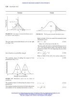
Rectangular fitted key (Fig. 17-1, Table 17-1)
Pressure between key and keyseat
FIGURE 17-1
d ¼ 3:035
ffiffiffiffi
D
p
to 3:45
ffiffiffiffi
D
p
SI ð17-1aÞ
where d and D are in mm
d ¼ 0:6
ffiffiffiffi
D
p
to 0:7
ffiffiffiffi
D
p
USCS ð17-1bÞ
where d and D are in in
d ¼ 0:096
ffiffiffiffi
D
p
to 0:11
ffiffiffiffi
D
p
SI ð17-1cÞ
where d and D are in m
Particular Formula
17.2 CHAPTER SEVENTEEN
Downloaded from Digital Engineering Library @ McGraw-Hill (www.digitalengineeringlibrary.com)
Copyright © 2004 The McGraw-Hill Companies. All rights reserved.
Any use is subject to the Terms of Use as given at the website.
KEYS, PINS, COTTERS, AND JOINTS
TABLE 17-1
Dimensions (in mm) of parallel keys and keyways
For shaft Above 6 8 10 12 17 22 30 38 44 50 58 65 75 85 95 110 130 150 170 200 230 260 290 330 380 440
diameters Up to 8 10 12 17 22 30 38 44 50 58 65 75 85 110 110 130 150 170 200 230 260 290 330 380 440 500
Key cross Width b 2 3 4 5 6 8 10 12 14 16 18 20 22 25 28 32 36 40 45 50 56 63 70 80 90 100
section Height h 2 3 4 5 6 7 8 8 9 10 11 12 14 14 16 18 20 22 25 28 32 32 36 40 45 50
Keyway depth In shaft t
1
1.2 1.8 2.5 3.0 3.5 4.0 5 5 5.5 6 7 7.5 8.5 9.0 10 11 12 13 15 17 19 20 22 25 28 31
(nominal) In hub t
2
1 1.4 1.8 2.3 2.8 3.3 3.3 3.8 3.8 4.3 4.4 4.9 5.4 5.9 6.4 7.4 8.4 9.4 10.4 11.4 12.4 13.4 14.4 15.4 17.4 19.5
t
1
þ0.05 þ0.1 þ0.15
Tolerance on À0.00 À0.0 À0.00
keyway depth t
2
þ0.05 þ0.1 þ0.15
À0.00 À0.0 À0.00
Chamfer or r max 0.25 0.35 0.55 0.80 1.30 2.00 2.95
radius of key r min 0.16 0.25 0.40 0.60 1.00 1.60 2.50
Keyway radius r
2
max 0.16 0.25 0.40 0.60 1.00 1.60 2.50
Length of key L min 6 6 8 10 14 18 22 28 36 45 50 56 63 71 80 90 100 110 125 140 160 180 200 220 250 280
L max 20 36 45 50 71 90 110 140 160 180 200 220 250 280 320 360 400 400 400 400 400 400 400 400 400 400
Source: IS 2048, 1962.
17.3
Downloaded from Digital Engineering Library @ McGraw-Hill (www.digitalengineeringlibrary.com)
Copyright © 2004 The McGraw-Hill Companies. All rights reserved.
Any use is subject to the Terms of Use as given at the website.
KEYS, PINS, COTTERS, AND JOINTS
Crushing strength
The tangential pressure per unit length of the key
at any intermediate distance L from the hub edge
(Fig. 17-1, Table 17-2)
The torque transmitted by the key (Fig. 17-1)
The general expression for torque transmitted accord-
ing to practical experience
For dimensions of tangential keys given here.
Shearing strength
The torque transmitted by the key (Fig. 17-1)
The shear stress at the dangerous point (Fig. 17-1)
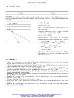
TAPER KEY (Fig. 17-2, Table 17-3)
The relation between the circumferential force F
t
and
the pressure F between the shaft and the hub
The pressure or compressive stress between the shaft
and the hub
The torque
p ¼ p
1
À L tan ð17-2Þ
where tan ¼
p
1
À p
2
L
2
¼
p
1
L
0
M
t
¼
1
2
p
1
DL
2
À DL
2
2
tan ð17-3Þ
M
t
¼
1
4
b1
hDL
2
À
1
18
b1
bL
2
2
ð17-4Þ
where p
2
¼ 0, when L
2
¼ L
o
¼ 2:25D;
tan ¼
p
1
L
o
¼
b1
h
4:5D
Refer to Table 17-2.
M
t
¼
1
2
1
bDL
2
À
1
9
1
bL
2
2
ð17-5Þ
where tan ¼
p
1
L
o
¼
1
b
2:25D
1
¼
M
t
L
2
bð0:5D À0:11L
2
Þ
ð17-6Þ
F
t
¼
1
F ð17-7Þ
F ¼ blp ð17-8Þ
M
t
¼
1
2
1
blpD ð17-9Þ
where
1
¼ coefficient of friction between the shaft
and the hub
¼ 0:25
Particular Formula
FIGURE 17-2
17.4 CHAPTER SEVENTEEN
Downloaded from Digital Engineering Library @ McGraw-Hill (www.digitalengineeringlibrary.com)
Copyright © 2004 The McGraw-Hill Companies. All rights reserved.
Any use is subject to the Terms of Use as given at the website.
KEYS, PINS, COTTERS, AND JOINTS
TABLE 17-2
Dimensions (in mm) of tangential keys and keyways
Keyway Keyway
Shaft Key Shaft Key
diameter, D Height, h Width, b Radius, r chamfer, a diameter, D Height, h Width, b Radius, r chamfer, a
100 10 30 2 3 460 46 138 4 5
110 11 30 2 3 480 48 144 5 6
120 12 36 2 3 500 50 150 5 6
130 13 39 2 3 520 52 156 5 6
140 14 42 2 3 540 54 162 5 6
150 15 45 2 3 560 56 168 5 6
160 16 48 2 3 580 58 174 5 6
170 17 51 2 3 600 60 180 6 7
180 18 54 2 3 620 62 186 6 7
190 19 57 2 3 640 64 192 6 7
200 20 60 2 3 660 66 198 6 7
210 21 63 2 3 680 68 204 6 7
220 22 66 2 4 700 70 210 6 7
230 23 69 3 4 720 72 216 6 7
240 24 72 3 4 740 74 222 6 7
250 25 75 3 4 760 76 228 6 7
260 26 78 3 4 780 78 234 6 7
270 27 81 3 4 800 80 240 6 7
280 28 84 3 4 820 82 246 6 7
290 29 87 3 4 840 84 252 6 7
300 30 90 3 4 860 86 258 6 7
320 32 95 3 4 880 88 264 8 9
340 34 102 3 4 900 90 270 8 9
360 36 108 3 4 920 92 276 8 9
380 38 114 4 5 940 94 282 8 9
400 40 129 4 5 960 96 288 8 9
420 42 126 4 5 980 98 294 8 9
440 44 132 4 5 1000 100 300 8 9
Notes: (1) The dimensions of the keys are based on the formula: width 0.3 shaft diameter, and thickness ¼0.1 shaft diameter; (2) if it is not possible
to fix the keys at 1208, they may be fixed at 1808; (3) it is recommended that for an intermediate diameter of shaft, the key section shall be the same
as that for the next larger size of the shaft in this table.
Source: IS 2291, 1963.
KEYS, PINS, COTTERS, AND JOINTS 17.5
Downloaded from Digital Engineering Library @ McGraw-Hill (www.digitalengineeringlibrary.com)
Copyright © 2004 The McGraw-Hill Companies. All rights reserved.
Any use is subject to the Terms of Use as given at the website.
KEYS, PINS, COTTERS, AND JOINTS
TABLE 17-3
Dimensions (in mm) of taper keys and keyways
Shaft Key Keyway in shaft and hub
Chamfer Keyway
Up to and Width, b or radius width, b Depth in Tolerance Depth in Tolerance Radius, r
2
,
Above including (h9) Height, hr
1
, min (D10) shaft, t
1
on t
1
hub, t
2
on t
2
max
6 8 2 2 0.16 2 1.2 þ0.05 0.5 0.16
8 10 3 3 — 3 1.8 — 0.9
10 12 4 4 4 2.5 1.2
12 17 5 5 5 3.0 1.7 þ0.1 0.25
17 22 6 6 0.25 6 3.5 2.1
22 30 8 7 — 8 4.0 þ0.10 2.5 —
30 38 10 8 10 5.0 2.5
38 44 12 8 12 5.0 2.5 —
44 50 14 9 0.40 14 5.5 2.9 0.40
50 58 16 10 — 16 6.0 — 3.4
58 65 18 11 18 7.0 3.3 —
65 75 20 12 20 7.5 3.8
75 85 22 14 0.60 22 8.5 4.8
85 95 25 14 — 25 9.0 4.3 þ0.2 0.60
95 110 28 18 28 10.0 5.3 —
110 130 32 10 32 11.0 6.2
130 150 36 25 36 12.0 7.2
150 170 40 22 1.00 40 13.0 þ0.15 8.2 1.00
170 200 45 25 — 45 15.0 9.2 — —
200 230 50 28 50 17.0 10.1
230 260 56 32 56 19.0 12.1
260 290 63 32 1.60 63 20.0 11.1 1.60
290 330 70 36 — 70 22.0 13.1 þ0.3 —
330 380 80 40 80 25.0 14.1
380 440 90 45 2.50 90 28.0 16,1 2.50
440 500 100 50 100 31.0 18.1
Source: IS 2292, 1963.
17.6
Downloaded from Digital Engineering Library @ McGraw-Hill (www.digitalengineeringlibrary.com)
Copyright © 2004 The McGraw-Hill Companies. All rights reserved.
Any use is subject to the Terms of Use as given at the website.
KEYS, PINS, COTTERS, AND JOINTS
The necessary length of the key
The axial force necessary to drive the key home
(Fig. 17-2)
The axial force is also given by the equation
FRICTION OF FEATHER KEYS (Fig. 17-3)
The circumferential force (Fig. 17-3)
The resistance to be overcome when a hub connected
to a shaft by a feather, Fig. 17-3a and subjected to
torque M
t
, is moved along the shaft
The equation for resistance R,if and
2
are equal
The equation for torque if two feather keys are used,
Fig. 17-3b
The force F
2
applied at key when two feather keys are
used, Fig. 17-3b
The resistance to be overcome when the hub con-
nected to the shaft by two feather keys Fig. 17-3b
and subjected to torque M
t
is moved along the shaft
For Gib-headed and Woodruff keys and keyways
l ¼
2M
t
1
bpD
ð17-10Þ
F
a
¼ F
þ F
¼ 2
2
F þF tan ð17-11Þ
where
2
¼ 0:10, tan ¼ 0:0104 if the taper is 1 in
100
F
a
¼ 0:21pbl ð17-12Þ
F
t
¼
M
t
a
ð17-13Þ
R ¼ F
t
þ
2
F
0
ð17-14Þ
¼ð þ
2
ÞF
t
ð17-15Þ
and F
0
¼ F
00
¼ F
t
¼force assumed to be acting at the shaft axis
without changing the equilibrium Fig. 17-3a
R ¼ 2F
t
ð17-16Þ
M
t
¼ 2F
2
a ð17-17Þ
F
2
¼
M
t
2a
þ
F
t
2
ð17-18Þ
R
2
¼ 2F
2
¼
R
2
ð17-19Þ
Refer to Tables 17-4 and 17-5.
Particular Formula
FIGURE 17-3 Feather key.
KEYS, PINS, COTTERS, AND JOINTS
17.7
Downloaded from Digital Engineering Library @ McGraw-Hill (www.digitalengineeringlibrary.com)
Copyright © 2004 The McGraw-Hill Companies. All rights reserved.
Any use is subject to the Terms of Use as given at the website.
KEYS, PINS, COTTERS, AND JOINTS
TABLE 17-4
Gib-head keys and keyways (all dimensions in mm)
Shaft diameter, d Key Key in shaft and hub
Chamber or Width of Radius at
Up to and Width, Height Tolerance Height of radius, keyway Depth in Tolerance Depth in Tolerance bottom of
Above including b (h9) (nominal) h on h gib-head, h
1
r
1
(min) (D10) shaft, t
1
on t
1
hub, t
2
on t
2
r
2ðmaxÞ
keyway
10 12 4 4 7 0.16 4 2.5 1.2 0.16
12 17 5 5 þ0.1 8 — 5 3 1.7
17 22 6 6 10 0.25 6 3.5 2.1 0.25
22 30 8 7 11 8 4 2.5
30 38 10 8 12 — 10 5 þ0.1 2.5 þ0.1
38 44 12 8 12 12 5 2.5 —
44 50 14 9 — 14 0.40 14 5.5 2.9
50 58 16 10 16 16 6 — 3.4 0.4
58 65 18 11 18 — 18 7 3.5
65 75 20 12 þ0.2 20 20 7.5 3.8 —
75 85 22 14 22 22 8.5 4.8
85 95 25 14 22 0.60 25 9 4.3 0.60
95 110 28 16 25 — 28 10 5.3 þ0.15
110 130 32 18 28 32 11 6.2 —
130 150 36 20 32 36 12 7.2
150 170 40 22 — 36 1.00 40 13 þ0.15 8.2 1.00
170 200 45 25 40 — 45 15 9.2
200 230 50 28 45 50 17 10.1 —
230 260 56 32 50 56 19 12.1
260 290 63 32 þ0.3 56 1.60 63 20 11.1 1.60
290 330 70 36 63 — 70 22 13.1 þ0.3
330 380 80 40 70 80 25 14.1 —
380 440 90 45 75 2.50 90 28 16.1
440 500 100 50 80 100 31 18.1 2.50
Source: IS 2293, 1963.
17.8
Downloaded from Digital Engineering Library @ McGraw-Hill (www.digitalengineeringlibrary.com)
Copyright © 2004 The McGraw-Hill Companies. All rights reserved.
Any use is subject to the Terms of Use as given at the website.
KEYS, PINS, COTTERS, AND JOINTS
TABLE 17-5
Woodruff keys and keyways (all dimensions in mm)
Range of shaft dia, d
Key Keyslot in shaft Keyslot in hub
Key section Group I Group II
Diameter of Chamfer Depth, t Depth t
1
Radius, r
1
bh Up to and Up to and tolerance Tolerance or Tolerance
(h9) (h12) Over including Over including d
1
on d
1
radius, r on r Length L Series A Series B Tolerance Series A Series B Tolerance Nominal Tolerance
1 1.4 3 4 6 8 4.0 0.2 3.82 1.0 1.0 0.6 0.6 0.2
1.5 2.6 4 6 8 10 7.0 0.2 6.76 2.0 2.0 0.8 0.8 0.2
2 2.6 6 8 10 12 7.0 0.2 6.76 1.8 1.8 1.0 1.0 0.2
2 3.7 6 8 10 12 10.0 0.2 9.66 2.9 2.9 1.0 1.0 0.2
2.5 3.7 8 10 12 17 10.0 0.2 9.66 2.9 2.9 1.0 1.0 0.2
3 3.7 8 10 12 17 10.0 0.2 9.66 2.5 2.8 1.4 1.1 0.2
3 5 8 10 12 17 13.0 0.2 þ0.1 12.65 3.8 4.1 1.4 1.1 0.2 À0. 1
3 6.5 — — 16 17 16.0 0.2 15.72 5.3 5.6 þ0.1 1.4 1.1 0.2
4 5 10 12 17 22 13.0 À0.1 0.2 12.65 3.5 4.1 1.7 1.1 0.2
4 6.5 10 12 17 22 16.0 0.2 15.72 5.0 5.6 1.7 1.1 0.2
4 7.5 — — 17 22 19.0 0.2 18.57 6.0 6.6 1.8 1.1 0.2
5 6.5 12 17 22 30 16.0 0.2 15.72 4.5 5.4 2.2 1.3 þ0.1 0.2
5 7.5 12 17 22 30 19.0 0.2 18.57 5.5 6.4 2.2 1.3 0.2
5 9 — — 22 30 22.0 0.2 21.63 7.0 7.9 þ0.2 2.2 1.3 0.2
6 7.5 17 22 30 38 19.0 0.4 18.57 5.1 6.0 2.6 1.7 0.4
6 9 17 22 30 38 22.0 0.4 21.63 6.6 7.5 þ0.1 2.6 1.7 0.4
6 (10) 17 22 30 38 25.0 À0.2 0.4 24.49 7.6 8.5 2.6 1.7 0.4
6 11 — — 30 38 28.0 À0.1 0.4 27.35 8.6 9.5 2.6 1.7 0.4
8 9 22 30 38 — 22.0 0.4 þ 0.2 21.63 6.2 7.5 3.0 1.7 0.4 À0.2
8 11 22 30 38 — 28.0 0.4 27.35 8.2 9.5 þ0.2 3.0 1.7 0.4
8 13 — — 38 — 32.0 0.4 31.43 10.2 11.5 3.0 1.7 0.4
10 11 30 38 38 — 28.0 À0.2 0.4 27.35 7.8 9.1 3.4 2.1 0.4
10 13 30 38 38 — 32.0 0.4 31.43 9.8 11.1 3.4 2.1 0.4
10 16 — — 38 — 45.0 0.4 43.08 12.8 14.1 3.4 2.1 0.4
Notes:
(1) The dimensions d Àt and d þ t
1
may be specified on workshop drawings; (2) the key size 6 Â10 is nonpreferred; (3) the key size 2:5 Â3:7 shall be used in automobile industries only.
Source: IS 2294, 1963.
17.9
Downloaded from Digital Engineering Library @ McGraw-Hill (www.digitalengineeringlibrary.com)
Copyright © 2004 The McGraw-Hill Companies. All rights reserved.
Any use is subject to the Terms of Use as given at the website.
KEYS, PINS, COTTERS, AND JOINTS
SPLINES
Parallel-sided or straight-sided spline
The torque which an integral multispline shaft can
transmit (Tables 17-6 to 17-12)
M
t
¼
1
2
phliðD À hÞð17-20Þ
Particular Formula
TABLE 17-6
Proportions of SAE standard parallel side splines
Bearing pressure, p
Types of spline fittings Symbols Proportions Fit MPa kpsi
w w ¼ 0:241D
h 4A, h ¼ 0:075D A 20.6 3.00
h 4B, h ¼ 0:125D B 13.7 2.00
w w ¼ 0:250D
h 6A, h ¼ 0:050D A 20.6 3.00
h 6B, h ¼ 0:075D B 13.7 2.00
h 6C, h ¼ 0:100D C 6.9 1.00
w w ¼ 0:156D
h 10A, h ¼ 0:045D A 20.6 3.00
h 10B, h ¼ 0:070D B 13.7 2.00
h 10C, h ¼ 0:095D C 6.9 1.00
w w ¼ 0:098D
h 16A, h ¼ 0:045D A 20.6 3.00
h 16B, h ¼ 0:070D B 13.7 2.00
h 16C, h ¼ 0:095D C 6.9 1.00
17.10 CHAPTER SEVENTEEN
Downloaded from Digital Engineering Library @ McGraw-Hill (www.digitalengineeringlibrary.com)
Copyright © 2004 The McGraw-Hill Companies. All rights reserved.
Any use is subject to the Terms of Use as given at the website.
KEYS, PINS, COTTERS, AND JOINTS
TABLE 17-7
Proportions of involute spline profile (American Standard)
Proportions
Spline characteristics Symbols P ¼
1
2
through
12
24
P ¼
6
32
through
48
96
Pitch diameter D
D ¼ zm ¼
z
P
D ¼ zm ¼ z=P
Circular pitch p p ¼ð=PÞ p ¼ð=PÞ
Tooth thickness t
t ¼
m
2
¼
2P
t ¼ðm=2Þ¼ð=2PÞ
Diametral pitch P
P ¼ð=pÞ P ¼ð=pÞ
Addendum a
a ¼ 0:5m ¼
0:500
P
a ¼ 0:5m ¼ 0:500=P
Dedendum (internal) b
1
b
1
¼ 0:90m ¼
0:900
P
b
1
¼ 0:9m ¼ 0:900=P
Dedendum b
b ¼ 0:5m ¼
0:500
P
b ¼ 0:5m ¼ 0:500=P
Dedendum (external) b
1
b
1
¼ 0:9m ¼ 0:900=Pb
1
¼ 1:0m ¼ 1:000=P
Major diameter (internal) D
oi
D
oi
¼ðz þ 1:8ÞmD
oi
¼ðz þ 1:8Þm
¼ðz þ 1:8Þ=P ¼ðz þ 1:8Þ=P
Minor diameter (external) D
me
D
me
¼ðz À 1:8ÞmD
me
¼ðz À 2:0Þm
¼ðz À 1:8Þ=P ¼ðz À 2:0Þ=P
Source: Courtesy H. L. Horton, ed., Machinery’s Handbook, 15th ed., The Industrial Press, New York, 1957.
KEYS, PINS, COTTERS, AND JOINTS 17.11
Downloaded from Digital Engineering Library @ McGraw-Hill (www.digitalengineeringlibrary.com)
Copyright © 2004 The McGraw-Hill Companies. All rights reserved.
Any use is subject to the Terms of Use as given at the website.
KEYS, PINS, COTTERS, AND JOINTS
TABLE 17-8
Straight sided splines (all dimensions in mm)
Minor Major
Nominal size No. of diameter, diameter, Width, d
1
,
a
e,
a
g, k, r, Centering
i Âd  D splines, id D B min max f
a
max mix max on
Light-Duty Series
6 Â 23 Â26 6 23 26 6 22.1 1.25 3.54 0.3 0.3 0.2
6 Â 26 Â30 6 26 30 6 24.6 1.84 3.85 0.3 0.3 0.2
g
Inside
6 Â 28 Â32 6 28 32 7 26.7 1.77 4.03 0.3 0.3 0.2 diameter
a
8 Â 32 Â36 8 32 36 6 30.4 1.89 2.71 0.4 0.4 0.3
8 Â 36 Â40 8 36 40 7 34.5 1.78 3.46 0.4 0.4 0.3
8 Â 42 Â46 8 42 46 8 40.4 1.68 5.03 0.4 0.4 0.3
8 Â 46 Â50 8 46 50 9 44.6 1.61 5.75 0.4 0.4 0.3
8 Â 52 Â58 8 52 58 10 49.7 2.72 4.89 0.5 0.5 0.5
8 Â 56 Â62 8 56 62 10 53.6 2.76 6.38 0.5 0.5 0.5 Inside
8 Â 62 Â68 8 62 68 12 59.8 2.48 7.31 0.5 0.5 0.5
g
diameter
10 Â 72 Â78 10 72 78 12 69.6 2.54 5.45 0.5 0.5 0.5 or flanks
b
10 Â 82 Â88 10 82 88 12 79.3 2.67 8.62 0.5 0.5 0.5
10 Â 92 Â98 10 92 98 14 89.4 2.36 10.08 0.5 0.5 0.5
10 Â 102 Â108 10 102 108 16 99.9 2.23 11.49 0.5 0.5 0.5
10 Â 112 Â120 10 112 120 18 108.8 3.23 10.72 0.5 0.5 0.5
Medium-Duty Series
6 Â 11 Â14 6 11 14 3 9.9 1.55 0.3 0.3 0.2
6 Â 13 Â16 6 13 16 3.5 12.0 1.50 0.32 0.3 0.3 0.2
6 Â 16 Â20 6 16 20 4 14.5 2.10 0.16 0.3 0.3 0.2
6 Â 18 Â22 6 18 22 5 16.7 1.95 0.45 0.3 0.3 0.2 Inside
6 Â 21 Â25 6 21 25 5 19.5 1.98 1.95 0.3 0.3 0.2
g
diameter
a
6 Â 23 Â28 6 23 28 6 21.3 2.30 1.34 0.3 0.3 0.2
6 Â 26 Â32 6 26 32 6 23.4 2.94 1.65 0.4 0.4 0.3
6 Â 28 Â34 6 28 34 7 25.9 2.94 1.70 0.4 0.4 0.3
8 Â 32 Â38 8 32 38 6 29.4 3.30 0.15 0.4 0.4 0.3
8 Â 36 Â42 8 36 42 7 33.5 3.01 1.02 0.4 0.4 0.3
8 Â 42 Â48 8 42 48 8 39.5 2.91 2.54 0.4 0.4 0.3
8 Â 46 Â54 8 46 54 9 42.7 4.10 0.86 0.5 0.5 0.3
8 Â 52 Â60 8 52 60 10 48.7 4.00 2.44 0.5 0.5 0.5 Inside
8 Â 56 Â65 8 56 65 10 52.2 4.74 2.50 0.5 0.5 0.5
g
diameter
8 Â 62 Â72 8 62 72 12 57.8 5.00 2.40 0.5 0.5 0.5 or flanks
b
10 Â 72 Â82 10 72 82 12 67.4 5.43 2.70 0.5 0.5 0.5
10 Â 82 Â92 10 82 92 12 77.1 5.40 3.00 0.5 0.5 0.5
10 Â 92 Â102 10 92 102 14 87.3 5.20 4.50 0.5 0.5 0.5
10 Â 102 Â112 10 102 112 16 97.7 4.90 6.30 0.5 0.5 0.5
10 Â 112 Â125 10 112 125 18 106.3 6.40 4.40 0.5 0.5 0.5
a
These values are based on the generating process.
b
Inside centering is not always possible with generating processes.
Source: IS 2327, 1963.
17.12
Downloaded from Digital Engineering Library @ McGraw-Hill (www.digitalengineeringlibrary.com)
Copyright © 2004 The McGraw-Hill Companies. All rights reserved.
Any use is subject to the Terms of Use as given at the website.
KEYS, PINS, COTTERS, AND JOINTS
Involute-sided spline
AMERICAN STANDARD (Table 17-7) The adden-
dum a and dedendum b for a flat root, Table 17-7
The area resisting shear, Table 17-7
The minimum height of contact on one tooth
The corresponding area of contact of all z teeth
The torque capacity of teeth in shear
The torque capacity of the spline in bearing with
b
¼ 2
dc
a ¼ b ¼ m ¼
1
P
ð17-21Þ
A
¼
DL
2
ð17-22Þ
h ¼ 0:8m ¼
0:8
P
¼
0:8D
z
ð17-23Þ
A ¼
0:8D
z
zL ¼ 0:8DL ð17-24Þ
M
t
¼
DL
z
D
2
d
¼ 0:7854D
2
L
d
ð17-25Þ
M
tb
¼ 0:8D
2
L
dc
ð17-26Þ
Particular Formula
TABLE 17-9
Tolerances for straight-sided splines (all dimensions in mm)
Tolerance on
Minor Major
diameter of diameter of
hub, d hub, D
Assembly of Width of hub B
splined hub Soft or Soft or
and shaft Soft or hardened hardened hardened
Splined hub For centering on inner
diameter or flanks
Shaft sliding or fixed D9 F10 H7 H11
For centering on inner
diameter
Shaft sliding inside hub h8 e8 f 7 a11
Splined shaft Shaft fixed in hub p6 h6 j6a11
Shaft sliding inside hub h8 e8— a11
For centering on flanks Shaft fixed in hub u6 k6 — a11
KEYS, PINS, COTTERS, AND JOINTS
17.13
Downloaded from Digital Engineering Library @ McGraw-Hill (www.digitalengineeringlibrary.com)
Copyright © 2004 The McGraw-Hill Companies. All rights reserved.
Any use is subject to the Terms of Use as given at the website.
KEYS, PINS, COTTERS, AND JOINTS
TABLE 17-10
Straight-sided splines for machine tools (all dimensions in mm)
4 Splines
Nominal size, Minor Major
i
a
 d  D diameter, d diameter, D Width, B
4 Â 11 Â15 11 15 3
4 Â 13 Â17 13 17 4
4 Â 16 Â20 16 20 6
4 Â 18 Â22 18 22 6
4 Â 21 Â25 21 25 8
4 Â 24 Â28 24 28 8
4 Â 28 Â32 28 32 10
4 Â 32 Â38 32 38 10
4 Â 36 Â42 36 42 12
4 Â 42 Â48 42 48 12
4 Â 46 Â52 46 52 14
4 Â 52 Â60 52 60 14
4 Â 58 Â65 58 65 16
4 Â 62 Â70 62 70 16
4 Â 68 Â78 68 78 16
a
i ¼ number of splines
Source: IS 2610, 1964.
6 Splines
Nominal size, Minor Major
i
a
 d  D diameter, d diameter, D Width, B
6 Â 21 Â 25 21 25 5
6 Â 23 Â 28 23 28 6
6 Â 26 Â 32 26 32 6
6 Â 28 Â 34 28 34 7
6 Â 32 Â 38 32 38 8
6 Â 36 Â 42 36 42 8
6 Â 42 Â 48 42 48 10
6 Â 46 Â 52 46 52 12
6 Â 52 Â 60 52 60 14
6 Â 58 Â 65 58 65 14
6 Â 62 Â 70 62 70 16
6 Â 68 Â 78 68 78 16
6 Â 72 Â 82 72 82 16
6 Â 78 Â 90 78 90 16
6 Â 82 Â 95 82 95 16
6 Â 88 Â 100 88 100 16
6 Â 92 Â 105 92 105 20
6 Â 98 Â 110 98 110 20
6 Â 105 Â 120 105 120 20
6 Â 115 Â 130 115 130 20
6 Â 130 Â 145 130 145 24
17.14 CHAPTER SEVENTEEN
Downloaded from Digital Engineering Library @ McGraw-Hill (www.digitalengineeringlibrary.com)
Copyright © 2004 The McGraw-Hill Companies. All rights reserved.
Any use is subject to the Terms of Use as given at the website.
KEYS, PINS, COTTERS, AND JOINTS
TABLE 17-11
Undercuts, chamfers, and radii for straight-sided splines
a
(all dimensions in mm)
External splines
Type A Type B Type M Internal splines Projected
Designation, tip width
i Âd  DBd
1
,min g, max f ,min hr
1
,max mnr
2
k, max r
3
, max of hub
4 Â 11 Â15 3 9.6 0.2 1.50 5.0 0.10 2.82 1.70 0.3 0.2 0.15 0.5
4 Â 13 Â17 4 11.8 0.2 2.37 5.5 0.10 3.76 1.70 0.3 0.2 0.15 0.5
4 Â 16 Â20 6 15.0 0.3 2.87 6.7 0.15 5.64 1.70 0.3 0.3 0.25 0.7
4 Â 18 Â22 6 16.9 0.3 4.35 7.7 0.15 5.64 1.70 0.3 0.3 0.25 0.7
4 Â 21 Â25 8 20.1 0.3 5.00 8.9 0.15 7.52 1.70 0.6 0.3 0.25 0.7
4 Â 24 Â28 8 23.0 0.3 7.30 10.4 0.15 7.52 1.70 0.6 0.3 0.25 0.7
4 Â 28 Â32 10 26.8 0.5 7.39 12.1 0.25 9.40 1.63 0.6 0.5 0.40 1.0
4 Â 32 Â38 10 30.3 0.5 9.56 14.2 0.25 9.40 2.55 0.6 0.5 0.40 1.0
4 Â 36 Â42 12 34.5 0.5 11.03 15.9 0.25 11.28 2.55 0.6 0.5 0.40 1.0
4 Â 42 Â48 12 40.2 0.5 15.41 19.0 0.25 11.28 2.55 1.0 0.5 0.40 1.0
4 Â 46 Â52 14 44.4 0.5 16.79 20.7 0.25 13.16 2.55 1.0 0.5 0.40 1.3
4 Â 52 Â60 14 49.5 0.5 21.63 23.7 0.25 13.16 3.40 1.0 0.5 0.40 1.3
4 Â 56 Â65 16 56.2 0.5 23.26 26.4 0.25 15.04 2.98 1.0 0.5 0.40 1.6
4 Â 62 Â70 16 59.5 0.5 23.61 28.3 0.25 15.04 3.40 1.0 0.5 0.40 1.6
4 Â 68 Â78 16 64.4 0.5 27.57 31.2 0.25 15.04 4.25 1.0 0.5 0.40 1.6
a
Four splines; see Fig. 17-4a.
Source: IS 2610, 1964
TABLE 17-12
Undercuts, chamfers, and radii for straight-sided splines
a
(all dimensions in mm)
External splines
Type A Type B Type M Internal splines Projected
Designation, tip width
i Âd  DBd
1
,min g, max f ,min hr
1
,max mnr
2
k, max r
3
, max of hub
6 Â 21 Â25 5 19.50 0.3 1.95 9.7 0.15 4.70 1.70 0.6 0.3 0.2 0.7
6 Â 23 Â28 6 21.30 0.3 1.34 11.0 0.15 5.64 2.13 0.6 0.3 0.2 0.7
6 Â 26 Â32 6 23.40 0.4 1.65 11.8 0.15 5.64 2.55 0.6 0.4 0.3 1.0
6 Â 28 Â34 7 25.90 0.4 1.70 12.9 0.25 6.58 2.55 0.6 0.4 0.3 1.0
6 Â 32 Â38 8 29.90 0.5 2.83 14.8 0.25 7.52 2.55 0.6 0.5 0.4 1.0
6 Â 36 Â42 8 33.70 0.5 4.95 16.5 0.25 7.52 2.55 0.6 0.5 0.4 1.0
6 Â 42 Â48 10 39.94 0.5 6.02 19.3 0.25 9.40 2.55 1.0 0.5 0.4 1.0
6 Â 46 Â52 12 44.16 0.5 5.81 21.1 0.25 11.28 2.55 1.0 0.5 0.4 1.3
6 Â 52 Â60 14 49.50 0.5 5.89 23.9 0.25 13.16 3.40 1.0 0.5 0.4 1.3
6 Â 58 Â65 14 55.74 0.5 8.29 26.7 0.25 13.16 3.98 1.0 0.5 0.4 1.6
6 Â 62 Â70 16 59.50 0.5 8.03 28.6 0.25 15.04 3.40 1.0 0.5 0.4 1.6
6 Â 68 Â78 16 64.40 0.5 9.73 31.4 0.25 15.04 4.25 1.0 0.5 0.4 1.6
6 Â 72 Â82 16 68.30 0.5 12.67 33.4 0.25 15.04 4.25 1.6 0.5 0.4 2.0
6 Â 78 Â90 16 73.00 0.5 13.07 36.2 0.25 15.04 5.10 1.6 0.5 0.4 2.0
6 Â 82 Â95 16 79.60 0.5 13.96 38.0 0.25 15.04 5.53 1.6 0.5 0.4 2.0
6 Â 88 Â100 16 82.90 0.5 17.84 41.3 0.25 15.04 5.10 1.6 0.5 0.4 2.0
6 Â 92 Â105 20 87.10 0.6 18.96 43.1 0.30 18.80 5.53 1.6 0.6 0.5 2.0
6 Â 98 Â110 20 93.40 0.6 19.22 46.4 0.30 18.80 5.10 2.0 0.6 0.5 2.0
6 Â 105 Â120 20 98.80 0.6 19.25 49.2 0.30 18.80 6.38 2.0 0.6 0.5 2.4
6 Â 115 Â130 20 108.4 0.6 24.75 54.2 0.30 18.80 6.38 2.5 0.6 0.5 2.4
6 Â 130 Â145 24 123.9 0.6 29.20 61.8 0.30 22.56 6.38 2.5 0.6 0.5 2.4
a
Six splines see Fig. 17-4b.
17.15
Downloaded from Digital Engineering Library @ McGraw-Hill (www.digitalengineeringlibrary.com)
Copyright © 2004 The McGraw-Hill Companies. All rights reserved.
Any use is subject to the Terms of Use as given at the website.
KEYS, PINS, COTTERS, AND JOINTS
The theoretical torque capacity of straight-sided
spline with sliding according to SAE
Equating the strength of the spline teeth in shear to
the shear strength of shaft, the length of spline for a
hollow shaft
The length of spline for a solid shaft
The effective length of spline for a hollow shaft used in
practice according to the SAE
For diametrical pitches used in involute splines (SAE
and ANSI)
INDIAN STANDARD (Figs. 17-4 and 17-5,
Tables 17-14 and 17-15)
The value of profile displacement (Fig. 17-4)
M
t
¼ 6:895 Â10
6
i
D þd
4
hL SI ð17-26aÞ
where
i ¼number of splines
D; d ¼diameter as shown in Table 17-7, m
d ¼inside diameter of spline, m
D ¼pitch diameter of spline, m
L ¼length of spline contact, m
h ¼minimum height of contact in one tooth of
spline, m
M
t
in N m
M
t
¼ 1000i
D þd
4
hL USCS ð17-26bÞ
where M
t
in lb in; d, D, L, and h in in
L ¼
D
3
me
ð1 ÀD
4
i
=D
4
me
Þ
4D
2
ð17-26cÞ
where
D
i
¼internal diameter of a hollow shaft, m (in)
D
me
¼minor diameter (external), m (in)
L ¼
D
3
me
4D
2
ð17-26dÞ
L
e
¼
D
3
me
ð1 ÀD
4
i
=D
4
me
Þ
D
2
ð17-26eÞ
For solid shaft D
i
¼ 0.
Refer to Table 17-13.
xm ¼
1
2
ðd
1
À mz À1:1mÞð17-27Þ
The value xm varies from À0:05m to þ0:45m
TABLE 17-13
Diametral pitches
a
used in involute splines (SAE and ANSI)
2:5
5
3
6
4
8
5
10
6
12
8
16
10
20
12
24
16
32
20
40
24
48
32
64
40
80
48
96
a
Diametral pitches are designated as fractions; the numerator of these fractions is the diametral pitch, P.
Particular Formula
17.16 CHAPTER SEVENTEEN
Downloaded from Digital Engineering Library @ McGraw-Hill (www.digitalengineeringlibrary.com)
Copyright © 2004 The McGraw-Hill Companies. All rights reserved.
Any use is subject to the Terms of Use as given at the website.
KEYS, PINS, COTTERS, AND JOINTS
The number of teeth
The minor diameter of the internal spline (Fig. 17-4a)
The major diameter of the external spline (Fig. 17-4a)
The minor diameter of the external spline (Fig. 17-4a)
z ¼
1
m
ðd
1
À 2xm À 1:1mÞð17-28Þ
d
2
¼ mz þ2xm À0:9m ¼ d
1
À 2m ð17-29Þ
d
3
¼ mz þ2xm þ0:9m ¼ d
1
À 0:2m ð17-30Þ
d
4
À mx þ 2xm À1:1m ¼ d
1
À 2:2m ð17-31Þ
Particular Formula
FIGURE 17-4(a) Reference profile of an involute-sided spline. (Source: IS 3665, 1966.)
FIGURE 17-4(b) Nomenclature of the involute spline profile.
FIGURE 17-5 Measurement between pins and measurement over pins of an involute-sided spline. (Source: IS 3665, 1966.)
KEYS, PINS, COTTERS, AND JOINTS
17.17
Downloaded from Digital Engineering Library @ McGraw-Hill (www.digitalengineeringlibrary.com)
Copyright © 2004 The McGraw-Hill Companies. All rights reserved.
Any use is subject to the Terms of Use as given at the website.
KEYS, PINS, COTTERS, AND JOINTS
TABLE 17-14
Dimensions (in mm) for involute splines of module 2
Internal spline External spline
Tooth
thickness
over z
0
teeth
Measure-
ment Measure- Tooth
Nominal Pin between Deviation Pin ment over Deviation thickness
size diameter, pins, factor, diameter pins, factor, deviation
d
1
 d
2
zd
o
d
b
d
3
d
4
d
5
,min d
6
, max xm l
o
¼ s
o
d Mi fi d Ma fa z
0
factor, 0.866
15 Â 11 6 12 10.392 14.6 10.6 14.68 10.92 þ0.4 3.603 3.5 7.629 2.42 5.5 22.212 1.11 2 9.121
17 Â 13 7 14 12.124 16.6 12.6 16.68 12.92 þ0.4 3.603 3.5 9.324 2.19 5.0 22.695 1.13 2 9.214
18 Â 14 7 14 12.124 17.6 13.6 17.68 13.92 þ0.9 4.181 3.5 10.379 1.61 6.0 25.588 1.06 2 9.714
20 Â 16 8 16 13.856 19.6 15.6 19.68 15.92 þ0.9 4.181 3.5 12.736 1.66 6.0 28.206 1.11 2 9.807
22 Â 18 9 18 15.588 21.6 17.6 21.68 17.92 þ0.9 4.181 3.5 14.460 1.64 5.5 28.790 1.13 — —
25 Â 21 11 22 19.053 24.6 20.6 24.68 20.92 þ0.4 3.603 3.5 17.478 1.96 4.5 29.898 1.28 — —
28 Â 24 12 24 20.785 27.6 23.6 27.68 23.92 þ0.9 4.181 3.5 20.738 1.68 5.0 34.161 1.23 3 15.621
30 Â 26 14 28 24.299 29.6 25.6 29.69 25.91 À0.1 3.326 3.5 22.484 2.41 4.0 34.144 1.46 3 14.807
32 Â 28 14 28 24.249 31.6 27.6 31.69 27.91 þ0.9 4.681 3.5 24.738 1.69 4.5 37.016 1.30 3 15.807
35 Â 31 16 32 27.713 34.6 30.6 34.69 30.91 þ0.4 3.603 3.5 27.711 1.88 4.0 39.000 1.42 3 15.493
38 Â 33 17 34 29.445 36.6 32.6 36.69 32.91 þ0.4 3.603 3.5 29.571 1.86 4.0 40.857 1.42 4 21.028
37 Â 34 18 36 31.177 37.6 33.6 37.69 33.91 À0.1 3.026 3.5 30.566 2.15 4.0 42.181 1.50 3 15.179
40 Â 36 18 36 31.177 39.6 35.6 39.69 35.91 þ0.9 4.181 3.5 32.739 1.70 4.0 45.137 1.15 4 21.621
42 Â 38 20 40 34.641 41.6 37.6 41.69 37.91 À0.1 3.026 3.5 34.589 2.08 4.0 46.195 1.52 4 20.807
45 Â 41 21 42 36.373 44.6 40.6 44.69 40.91 þ0.4 3.603 3.5 37.604 1.84 4.0 48.938 1.46 4 21.400
47 Â 43 22 44 38.105 46.6 42.6 46.69 42.91 þ0.4 3.603 3.5 39.720 1.84 4.0 51.074 1.47 4 21.493
48 Â 44 22 44 38.105 47.6 43.6 47.69 43.91 þ0.9 4.181 3.5 40.740 1.70 4.0 51.912 1.43 5 27.435
50 Â 46 24 48 41.569 49.6 45.6 49.69 45.91 À0.1 3.026 3.5 42.621 2.00 4.0 54.218 1.54 4 21.179
ð52 Â 48Þ 24 48 41.569 51.6 47.6 51.69 47.91 þ0.9 4.181 3.5 44.740 1.71 4.0 55.939 1.44 5 27.621
55 Â 51 26 52 45.033 54.6 50.6 54.70 50.90 þ0.4 3.603 3.5 47.724 1.82 4.0 59.109 1.50 5 27.307
ð58 Â 54Þ 28 56 48.497 57.6 53.6 57.70 53.90 À0.1 3.026 3.5 50.624 1.95 4.0 62.235 1.56 5 26.993
60 Â 56 28 56 48.497 59.6 55.6 59.70 55.90 þ0.9 4.181 3.5 52.740 1.71 4.0 63.984 1.47 6 33.435
ð62 Â 58Þ 30 60 51.962 61.6 57.6 61.70 57.90 À0.1 3.026 3.5 54.650 1.93 4.0 66.242 1.57 5 27.179
65 Â 61 31 62 53.694 64.6 60.6 64.70 60.90 þ0.4 3.600 3.5 57.648 1.80 4.0 69.058 1.53 6 33.214
ð68 Â 64Þ 32 64 55.426 67.6 63.6 67.70 63.90 þ0.9 4.181 3.5 60.740 1.71 4.0 72.021 1.49 6 33.807
70 Â 66 34 68 58.890 69.6 65.6 69.70 65.90 À0.1 3.026 3.5 62.663 1.90 4.0 74.253 1.59 6 32.993
ð72 Â 68Þ 34 68 58.890 71.6 67.6 71.70 67.90 þ0.9 4.181 3.5 64.740 1.71 4.0 76.036 1.50 7 39.435
75 Â 71 36 72 62.354 74.6 70.6 74.70 70.90 þ0.4 3.603 3.5 67.729 1.79 4.0 79.166 1.55 7 39.121
ð78 Â 74Þ 38 76 65.818 77.6 73.6 77.70 73.90 À0.1 3.026 3.5 70.672 1.88 4.0 82.263 1.60 7 38.807
80 Â 76 38 76 65.818 79.6 75.6 79.70 75.90 þ0.9 4.181 3.5 72.740 1.72 4.0 84.063 1.52 7 39.807
ð82 Â 78Þ 40 80 69.283 81.6 77.6 81.70 77.90 À0.1 3.026 3.5 74.676 1.87 4.0 86.267 1.61 7 38.993
Note: Values within parentheses are nonpreferred.
17.18
Downloaded from Digital Engineering Library @ McGraw-Hill (www.digitalengineeringlibrary.com)
Copyright © 2004 The McGraw-Hill Companies. All rights reserved.
Any use is subject to the Terms of Use as given at the website.
KEYS, PINS, COTTERS, AND JOINTS
TABLE 17-15
Dimensions (in mm) for involute spline of module 2.5
Internal spline External spline
Tooth
thickness
over z
0
teeth
Measure-
ment Measure- Tooth
Nominal Pin between Deviation Pin ment over Deviation thickness
size diameter, pins, factor, diameter pins, factor, deviation
d
1
 d
2
zd
o
d
b
d
3
d
4
d
5
,min d
6
, max xm l
o
¼ s
o
d Mi fi d Ma fa z
0
factor, 0.866
20 Â 15 6 15.0 12.990 19.5 14.5 19.58 14.92 þ1.125 5.226 4.6 10.552 1.71 9.0 33.258 1.03 2 12.026
22 Â 17 7 17.5 15.155 21.5 16.5 21.58 16.92 þ0.875 4.937 4.5 12.105 1.85 7.0 30.558 1.08 2 11.892
25 Â 20 8 20.0 17.321 24.5 19.5 24.58 19.92 þ1.125 5.226 4.5 15.552 1.72 7.0 34.113 1.13 2 12.252
28 Â 23 10 25.0 21.651 27.5 22.5 27.58 22.92 þ0.125 4.071 4.55 19.116 2.30 5.0 33.006 1.37 2 11.491
30 Â 25 10 25.0 21.651 29.5 24.5 29.58 24.92 þ1.125 5.226 4.5 20.552 1.72 6.5 38.151 1.19 3 19.293
32 Â 27 11 27.5 23.816 31.5 26.5 31.59 26.91 þ0.875 4.937 4.5 22.265 1.81 6.0 38.835 1.23 3 19.160
35 Â 30 12 30.0 25.981 34.5 29.5 34.59 29.91 þ1.125 5.226 4.5 25.552 1.72 6.0 42.093 1.25 3 19.526
37 Â 32 13 32.5 28.146 36.5 31.5 36.59 31.91 þ0.875 4.937 4.5 27.308 1.80 5.5 42.764 1.30 3 19.392
38 Â 33 14 35.0 30.311 37.5 32.5 37.59 32.91 þ0.125 4.071 4.5 28.316 2.26 5.0 43.096 1 43 3 18.759
40 Â 35 14 35.0 30.311 39.5 34.5 39.59 34.91 þ1.125 5.226 4.5 30.552 1.72 6.0 47.204 1.28 3 19.759
42 Â 37 15 37.5 32.476 41.5 36.5 41.59 36.91 þ0.875 4.937 4.5 32.340 1.79 5.5 47.881 1.33 3 19.625
45 Â 40 16 40.0 34.641 44.5 39.5 44.59 39.91 þ1.125 5.226 4.5 35.552 1.73 5.5 51.035 1.33 4 26.793
47 Â 42 17 42.5 36.806 46.5 41.5 46.59 41.91 þ0.875 4.937 4.5 37.365 1.78 5.5 52.974 1.36 4 26.660
48 Â 43 18 45.0 38.971 47.5 42.5 47.59 42.91 þ0.125 4.071 4.5 38.387 2.07 5.0 53.156 1.47 4 26.026
50 Â 45 18 43.0 38.971 49.5 44.5 49.59 44.91 þ1.125 5.226 4.5 40.552 1.73 5.5 56.100 1.36 4 27.026
ð52 Â 47Þ 19 47.5 41.136 51.5 46.5 51.59 46.91 þ0.875 4.937 4.5 42.384 1.78 5.5 58.052 1.38 4 29.892
55 Â 50 20 50.0 43.301 54.5 49.5 54.59 49.91 þ1.125 5.226 4.5 45.552 1.73 5.5 61.157 1.38 4 27.259
ð58 Â 53Þ 22 55.0 47.631 57.5 52.5 57.60 52.90 þ0.125 4.071 4.5 48.424 1.99 5.0 63.198 1.51 4 26.491
60 Â 55 22 55.0 47.631 59.5 54.5 59.60 54.90 þ1.125 5.226 4.5 50.552 1.73 5.5 66.206 1.40 5 34.193
ð62 Â 57Þ 23 57.5 49.796 61.5 56.5 61.60 56.10 þ0.875 4.937 4.5 52.413 1.77 5.0 66.846 1.45 5 34.160
65 Â 60 24 60.0 51.962 64.5 59.5 64.60 56.90 þ1.125 5.226 4.5 55.552 1.73 5.0 69.924 1.44 5 34.526
ð68 Â 63Þ 26 65.0 56.292 67.5 62.5 67.60 59.90 þ0.125 4.071 4.5 58.448 1.94 5.0 73.229 1.53 5 33.759
70 Â 65 26 65.0 56.292 69.5 64.5 69.60 64.90 þ1.125 5.226 4.5 60.552 1.73 5.0 74.954 1.46 5 34.759
ð72 Â 67Þ 27 67.5 58.457 71.5 66.5 71.60 66.90 þ0.875 4.937 4.5 62.434 1.77 5.0 76.920 1.48 5 34.625
75 Â 70 28 70.0 60.622 74.5 69.5 74.60 69.90 þ1.125 5.226 4.5 65.552 1.73 5.0 79.981 1.47 6 41.793
ð78 Â 73Þ 30 75.0 64.952 77.5 72.5 77.60 72.90 þ0.125 4.071 4.5 62.464 1.90 5.0 83.253 1.55 6 41.026
80 Â 75 30 75.0 64.952 79.5 74.5 79.60 74.90 þ1.125 5.226 4.5 70.552 1.73 5.0 85.004 1.48 6 42.026
ð82 Â 77Þ 31 77.5 67.117 81.5 77.5 81.60 77.90 þ0.875 4.937 4.5 72.449 1.76 5.0 86.978 1.50 6 41.892
85 Â 80 32 80.0 69.282 84.5 79.5 84.60 79.90 þ1.125 5.226 4.5 75.552 1.73 5.0 90.026 1.49 6 42.259
ð88 Â 83Þ 34 85.0 73.612 87.5 82.5 87.60 82.90 þ0.125 4.071 4.5 78.476 1.88 5.0 93.273 1.57 6 41.491
90 Â 85 34 85.0 73.612 89.5 84.5 89.60 84.90 þ1.125 5.226 4.5 80.552 1.73 5.0 95.045 1.50 7 49.293
ð92 Â 87Þ 35 87.5 75.777 91.5 86.5 91.60 86.90 þ0.875 4.937 4.5 82.461 1.76 5.0 97.024 1.52 7 49.160
95 Â 90 36 90.0 77.942 94.5 89.5 94.60 89.90 þ1.125 5.226 4.5 85.552 1.73 5.0 100.063 1.51 7 49.526
ð98 Â 93Þ 38 95.0 82.272 97.5 92.5 97.60 92.90 þ0.125 4.071 4.5 88.485 1.86 5.0 103.288 1.58 7 48.759
100 Â 95 38 95.0 82.272 99.5 94.5 99.60 94.60 þ1.125 5.226 4.5 90.552 1.73 5.0 105.079 1.52 7 49.759
105 Â 100 40 100.0 86.603 104.5 99.5 104.60 99.90 þ1.125 5.226 4.5 95.552 1.73 5.0 110.094 1.53 8 56.793
Note: Values within brackets are nonpreferred.
17.19
Downloaded from Digital Engineering Library @ McGraw-Hill (www.digitalengineeringlibrary.com)
Copyright © 2004 The McGraw-Hill Companies. All rights reserved.
Any use is subject to the Terms of Use as given at the website.
KEYS, PINS, COTTERS, AND JOINTS
The value of tooth thickness and space width of spline
PINS
Taper pins
The diameter at small end (Figs. 17-6 and 17-7, Tables
17-16 and 17-17)
The mean diameter of pin
FIGURE 17-6 Tapered pin.
Sleeve and taper pin joint (Fig. 17-7)
AXIAL LOAD
The axial stress induced in the hollow shaft (Fig. 17-7)
due to tensile force F
The bearing stress in the pin due to bearing against
the shaft an account of force F
The bearing stress in the pin due to bearing against
the sleeve
The shear stress in pin
The shearing stress due to double shear at the end of
hollow shaft
The shear stress due to double shear at the sleeve end
l
o
¼ s
o
¼ m
2
þ 2xm tan ð17-32Þ
d
ps
¼ d
pl
À 0:0208l ð17-33Þ
d
m
¼ 0:20D to 0:25D ð17-34Þ
FIGURE 17-7 Sleeve and tapered pin joint for hollow
shafts.
¼
F
4
ðd
2
2
À d
2
1
ÞÀ2ðd
2
À d
1
Þd
m
ð17-35Þ
c
¼
F
2ðd
2
À d
1
Þd
m
17-36Þ
c
¼
F
2ðd
3
À d
2
Þd
m
ð17-35Þ
¼
2F
d
2
m
ð17-38Þ
¼
F
2ðd
2
À d
1
Þl
2
ð17-39Þ
¼
F
2ðd
3
À d
2
Þl
1
ð17-40Þ
Particular Formula
17.20 CHAPTER SEVENTEEN
Downloaded from Digital Engineering Library @ McGraw-Hill (www.digitalengineeringlibrary.com)
Copyright © 2004 The McGraw-Hill Companies. All rights reserved.
Any use is subject to the Terms of Use as given at the website.
KEYS, PINS, COTTERS, AND JOINTS
TABLE 17-16
Dimensions (in mm) for cylindrical pins
Nominal diameter, d
nom
,mm
1.52 2.53 4 5 6 8 1012162025324050
d
m6
Max 1.61 2.01 2.51 3.01 4.01 5.01 6 01 8.02 10.02 12.02 16.02 20.02 25.02 32.02 40.02 50.02
Min 1.60 2.00 2.50 3.00 4.00 5.00 6.00 8.01 10.01 12.01 16.01 20.01 25.01 32.01 40.01 50.01
d
h6
Max 1.60 2.00 2.50 3.00 4.00 5.00 6.00 8.00 10.00 12.00 16.00 20.00 25.00 32.00 40.00 50.00
Min 1.59 1.99 2.49 2.99 3.98 4.98 5.98 7.98 9.98 11.97 15.97 19.97 24.97 31.96 39.96 49.96
d
h11
Max 1.60 2.00 1.50 3.00 4.00 5.00 6.00 8.00 10.00 12.00 16.00 20.00 25.00 32.00 40.00 50.00
Min 1.54 1.94 2.44 2.94 3.92 4.92 5.92 7.91 9.91 11.89 15.89 19.87 24.87 31.84 39.84 49.84
a
max
0.20 0.25 0.30 0.40 0.50 0.63 0.80 1.00 1.20 1.60 2.00 2.50 3.00 4.00 5.00 6.30
r
nom
1.50 2.00 2.50 3.00 4.00 5.00 6.00 8.00 10.00 12.00 16.00 20.00 25.00 32.00 40.00 50.00
c 0.30 0.35 0.40 0.50 0.63 0.80 1.60 2.00 2.50 3.00 3.50 4.00 5.00 6.30 8.00
Source: IS 2393, 1980.
TABLE 17-17
Dimensions (in mm) for solid and split taper pins
d
nom
1.52 2.53 4 5 6 8 1012162025324050
d
h10
Max 1.50 2.00 2.50 3.00 4.00 5.00 6.00 8.00 10.00 12.00 16.00 20.00 25.00 32.00 40.00 50.00
Min 1.46 1.96 2.46 2.94 3.95 4.95 5.95 7.94 9.94 11.93 15.63 19.92 24.92 31.90 39.90 49.90
a 0.20 0.25 0.30 0.35 0.40 0.63 0.80 1.00 1.20 1.60 2.00 2.50 3.00 4.00 5.00 6.30
Source: IS 549, 1974.
17.21
Downloaded from Digital Engineering Library @ McGraw-Hill (www.digitalengineeringlibrary.com)
Copyright © 2004 The McGraw-Hill Companies. All rights reserved.
Any use is subject to the Terms of Use as given at the website.
KEYS, PINS, COTTERS, AND JOINTS
The axial stress in the sleeve
TORQUE
The shear due to twisting moment applied
For the design of hollow shaft subjected to torsion
Taper joint and nut
The tensile stress in the threaded portion of the rod
(Fig. 17-8) without taking into consideration stress
concentration
FIGURE 17-8 Tapered joint and nut.
The bearing resistance offered by the collar
The diameter of the taper d
2
Provide a taper of 1 in 50 for the length (l À l
1
Þ
Knuckle joint
The tensile stress in the rod (Fig. 17-9)
The tensile stress in the net area of the eye
Stress in the eye due to tear of
¼
F
4
ðd
2
3
À d
2
2
ÞÀ2ðd
3
À d
2
Þd
m
ð17-41Þ
¼
M
t
4
d
2
m
d
2
ð17-42Þ
Refer to Chapter 14.
t
¼
F
4
d
2
c
ð17-43Þ
c
¼
F
4
ðd
2
3
À d
2
2
Þ
ð17-44Þ
d
2
> d
nom
ð17-45Þ
t
¼
4F
d
2
ð17-46Þ
t
¼
F
ðd
4
À d
2
Þb
ð17-47Þ
tn
¼
F
bðd
4
À d
2
Þ
ð17-48Þ
Particular Formula
17.22 CHAPTER SEVENTEEN
Downloaded from Digital Engineering Library @ McGraw-Hill (www.digitalengineeringlibrary.com)
Copyright © 2004 The McGraw-Hill Companies. All rights reserved.
Any use is subject to the Terms of Use as given at the website.
KEYS, PINS, COTTERS, AND JOINTS
Tensile stress in the net area of the fork ends
Stress in the fork ends due to tear of
Compressive stress in the eye due to bearing pressure
of the pin
Compressive stress in the fork due to the bearing
pressure of the pin
Shear stress in the knuckle pin
The maximum bending moment, Fig. 17-9 (panel b)
The maximum bending stress in the pin, based on the
assumption that the pin is supported and loaded as
shown in Fig. 17-9b and that the maximum bending
moment M
b
occurs at the center of the pin
The maximum bending moment on the pin based on
the assumption that the pin supported and loaded
as shown in Fig. 17-10b, which occurs at the center
of the pin
The maximum bending stress in the pin based on the
assumption that the pin is supported and loaded
shown in Fig. 17-10b
i
¼
F
2aðd
4
À d
2
Þ
ð17-49Þ
tr
¼
F
2aðd
4
À d
2
Þ
ð17-50Þ
e
¼
F
d
2
b
ð17-51Þ
c
¼
F
2d
2
a
ð17-52Þ
¼
2F
d
2
2
ð17-53Þ
M
b
¼
Fb
8
ð17-54Þ
b
¼
4Fb
d
3
2
ð17-55Þ
M
b
¼
F
2
b
4
þ
a
3
ðapprox:Þð17-56Þ
b
¼
4ð3b þ4aÞF
3d
3
2
ð17-57Þ
Particular Formula
FIGURE 17-9 Knuckle joint for round rods.
KEYS, PINS, COTTERS, AND JOINTS
17.23
Downloaded from Digital Engineering Library @ McGraw-Hill (www.digitalengineeringlibrary.com)
Copyright © 2004 The McGraw-Hill Companies. All rights reserved.
Any use is subject to the Terms of Use as given at the website.
KEYS, PINS, COTTERS, AND JOINTS