Machine Design Databook Episode 2 part 4 pdf
Bạn đang xem bản rút gọn của tài liệu. Xem và tải ngay bản đầy đủ của tài liệu tại đây (1018.85 KB, 40 trang )
The total frictional torque for V-thread, including
collar friction torque
The mean diameter of collar
Ã
Substituting the value of d
c
in Eq. (18-30a) and after
simplifying
The torque factor
The efficiency of square thread neglecting collar
friction
The efficiency formula for an angular-type thread
with half apex angle and an allowance for nut or
end friction on a radius r
c
The efficiency formula for square thread
LOADING
Lowering the load
The tangential force at mean or pitch radius r
2
¼ r
m
The frictional torque at mean or pitch radius r
2
¼ r
m
The condition for overhauling for square threads
M
t
¼ W
d
2
2
tan þ
cos
1 À
tan
cos
0
B
@
1
C
A
þ
c
d
c
2
2
6
4
3
7
5
ð18-30aÞ
d
c
¼ðd þ 1:5dÞ=2 ð18-30bÞ
M
t
¼ K
F
i
d ð18-30cÞ
where K
is the torque factor
W ¼ F
i
¼ preload, N (lbf)
K
¼
d
2
2d
tan þ
cos
1 À
tan
cos
0
B
@
1
C
A
þ
c
 0:625 ð18-30dÞ
where d
2
¼ d
m
Refer to Table 18-5b for K
.
¼
tan
tanð þ Þ
¼
Wl
2M
t
ð18-31Þ
¼
d
2
tan
tan þ = cos
1 À tan = cos
d
2
þ
c
d
c
ð18-32Þ
¼
d
2
tan
tan þ
1 À tan
d
2
þ
c
d
c
ð18-33Þ
¼
l
½d
2
tanð þ Þþ
c
d
c
ð18-34Þ
F
t
¼ W tanð þ Þð18-35Þ
M
t
¼
Wd
2
2
tanð À Þð18-36Þ
tan !
d
2
þ
c
d
c
d
2
À
c
d
c
ð18-37Þ
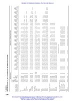
Particular Formula
Ã
Since the flat faces of hexagonal nut is same as the diameter of washer face which is 1.5 times the nominal diameter d.
THREADED FASTENERS AND SCREWS FOR POWER TRANSMISSION
18.13
Downloaded from Digital Engineering Library @ McGraw-Hill (www.digitalengineeringlibrary.com)
Copyright © 2004 The McGraw-Hill Companies. All rights reserved.
Any use is subject to the Terms of Use as given at the website.
THREADED FASTENERS AND SCREWS FOR POWER TRANSMISSION
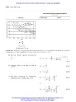
Differential screws (Fig. 18-3G)
The loading efficiency of a differential screw, not
including the collar friction
Compound screws
The loading efficiency of a compound screw, not
including collar friction
The number of threads necessary in the nut
The length of nut
¼
D
o
tan
o
À D
i
tan
i
D
o
tan
o
þ
o
1 À
o
tan
o
À D
i
tan
i
þ
i
1 À
i
tan
i
ð18-38Þ
¼
D
o
tan
o
þ D
i
tan
i
D
o
tan
o
þ
o
1 À
o
tan
o
þ D
i
tan
i
þ
i
1 À
i
tan
i
ð18-39Þ
i ¼
4W
0
b
ðd
2
À d
2
i
Þ
ð18-40Þ
l
n
¼ iP ¼
4WP
0
b
ðd
2
À d
2
1
Þ
ð18-41Þ
TABLE 18-5c
Metric mechanical-property classes for steel bolts, screws, and studs
a
Minimum Minimum Minimum
Size proof tensile yield
Property range strength,
sp
strength,
st
strength,
sy
Head
class inclusive MPa MPa MPa Material marking
4.6 M5–M36 225 400 240 Low or medium carbon
4.8 M1.6–M16 310 420 340 Low or medium carbon
5.8 M5–M24 380 520 420 Low or medium carbon
8.8 M16–M36 600 830 660 Medium carbon, Q and T
9.8 M1.6–M16 650 900 720 Medium carbon, Q and T
10.9 M5–M36 830 1040 940 Low-carbon martensite, Q and T
12.9 M1.6–M36 970 1220 1100 Alloy, Q and T
a
The thread length for bolts and cap screws is
L
T
¼
2d þ 6 L 125
2d þ 12 125 < L 200
2d þ 25 L > 200
8
>
<
>
:
where L is the bolt length. The thread length for structural bolts is slightly shorter than given above.
Particular Formula
18.14 CHAPTER EIGHTEEN
Downloaded from Digital Engineering Library @ McGraw-Hill (www.digitalengineeringlibrary.com)
Copyright © 2004 The McGraw-Hill Companies. All rights reserved.
Any use is subject to the Terms of Use as given at the website.
THREADED FASTENERS AND SCREWS FOR POWER TRANSMISSION
TABLE 18-5d
Grade identification marks and mechanical properties of bolts and screws
Size Min. strength (10
3
psi) Material
range and
Identifier Grade (in) Proof Tensile Yield treatment
A SAE Grade 1
1
4
to 1
1
2
33 60 36 Low or medium carbon
ASTM A307
1
4
to 1
1
2
33 60 36 Low carbon
SAE Grade 2
1
4
to
3
4
55 74 57 Low or medium carbon
7
8
to 1
1
2
33 60 36
SAE Grade 4
1
4
to 1
1
2
65 115 100 Medium carbon, cold drawn
B SAE Grade 5 and
ASTM A449
1
4
to 1 85 120 92 Medium carbon, Q and T
SAE Grade 5, ASTM A449 1
1
8
to 1
1
2
74 105 81
ASTM A449 1
3
4
to 3 55 90 58
C SAE Grade 5.2
1
4
to 1 85 120 92 Low-carbon martensite, Q and T
D ASTM A325, Type 1
1
2
to 1 85 120 92 Medium carbon, Q and T
1
1
8
to 1
1
2
74 105 81
E ASTM A325, Type 2
1
2
to 1 85 120 92 Low carbon martensite, Q and T
1
1
8
to 1
1
2
74 105 81
F ASTM A325, Type 3
1
2
to 1 85 120 92 Weathering steel, Q and T
1
1
8
to 1
1
2
74 105 81
G ASTM A354, Grade BC
1
4
to 2
1
2
105 125 109 Alloy-steel, Q and T
2
3
4
to 4 95 115 99
H SAE Grade 7
1
4
to 1
1
2
105 133 115 Medium carbon alloy, Q and T
I SAE Grade 8
1
4
to 1
1
2
120 150 130 Medium carbon alloy, Q and T
ASTM A354, Grade BD
1
4
to 1
1
2
120 150 130 Alloy-steel, Q and T
J SAE Grade 8.2
1
4
to 1 120 150 130 Low-carbon martensite, Q and T
K ASTM A490, Type 1
1
2
to 1
1
2
120 150 130 Alloy-steel, Q and T
L ASTM A490, Type 3
1
2
to 1
1
2
120 150 130 Weathering steel, Q and T
THREADED FASTENERS AND SCREWS FOR POWER TRANSMISSION
18.15
Downloaded from Digital Engineering Library @ McGraw-Hill (www.digitalengineeringlibrary.com)
Copyright © 2004 The McGraw-Hill Companies. All rights reserved.
Any use is subject to the Terms of Use as given at the website.
THREADED FASTENERS AND SCREWS FOR POWER TRANSMISSION
The required length of engagement for adequate shear
strength (assuming that the load is distributed over
the threads in contact)
Neglecting the radial clearance between threads, or
allowance at the major and minor diameters and con-
sidering the threads as a series of collars the equation
for thread engagement
The normal length of thread engagement as per
Indian standard
Note:
If l
eN
has to be between the limits, the length of the
thread is said to be normal ðNÞ
If l
eN
has to be below the minimum level, length of
thread is said to be short ðSÞ
If l
eN
has to be above the maximum level, length of
thread is said to be long ðLÞ
Eccentric loading
The load on bolt 1, Fig. 18-5 (panel a)
The general expression for the load carried by ith bolt,
F
i
The maximum load on the bolt, Fig. 18-5(b)
The maximum load on the bolt, Fig. 18-5(c)
l
c
¼
nPF
A
ð18-42Þ
l
eðscrewÞ
¼
nPF
d
1
t
1
ðscrewÞ
ð18-43Þ
l
eðnutÞ
¼
nPF
dt
ðnutÞ
ð18-44Þ
l
eNðminÞ
¼ 8:92Pd
0:2
SI ð18-45aÞ
where l
eN
, P, and d in m
l
eNðminÞ
¼ 2:24Pd
0:2
SI ð18-45bÞ
where l
eN
, P, and d in mm
l
eNðmaxÞ
¼ 26:67Pd
0:2
SI ð18-46aÞ
where l
eN
, P, and d in m
l
eNðmaxÞ
¼ 6:7Pd
0:2
SI ð18-46bÞ
where l
eN
, P, and d in mm
F
1
¼
Fll
1
l
2
1
þ l
2
2
þ l
2
3
þ l
2
4
¼ F
lða Àb cos Þ
4a
2
þ 2b
2
ð18-47Þ
F
i
¼ F
2lða Àb cos Þ
ð2a
2
þ b
2
Þi
ð18-48Þ
F
max
¼
2Flða þbÞ
ð2a
2
þ b
2
Þi
ð18-49Þ
F
max
¼
2Fl a þ b cos
1808
i
"#
ð2a
2
þ b
2
Þi
ð18-50Þ
Particular Formula
18.16 CHAPTER EIGHTEEN
Downloaded from Digital Engineering Library @ McGraw-Hill (www.digitalengineeringlibrary.com)
Copyright © 2004 The McGraw-Hill Companies. All rights reserved.
Any use is subject to the Terms of Use as given at the website.
THREADED FASTENERS AND SCREWS FOR POWER TRANSMISSION
Fastening of a bracket
Bracket with no preload
Tensile load taken by the bolts, Fig. 18-6(a)
Shear stresses
(i) If shear load is taken completely by the lug, shear
load on lug is given by
(ii) If shear load is taken completely by the bolt shear
load on each bolt is given by
(iii) If shear load is shared equally between the bolt
and the lug
Shear load due to the eccentricity e, Fig. 18-6(b), in
each bolt is given by
Resultant shear load
F
1
¼
Fll
1
2ðl
2
1
þ l
2
2
þ l
2
3
Þ
ð18-51Þ
F
2
¼
Fll
2
2ðl
2
1
þ l
2
2
þ l
2
3
Þ
ð18-52Þ
F
3
¼
Fll
3
2ðl
2
1
þ l
2
2
þ l
2
3
Þ
ð18-53Þ
F
1
¼ F ð18-54Þ
F
b
¼
F
i
ð18-55Þ
F
0
1
¼
F
2
ð18-56Þ
F
0
b
¼
F
2i
ð18-57Þ
F
0
ei
¼
Fex
i
P
x
2
i
ð18-58Þ
where x
i
¼ distance between the center of bolts and
the center of the particular bolt
F
r
¼ F
b
ðor F
0
b
Þþ
Fex
i
P
x
2
i
ð18-59Þ
Particular Formula
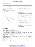
FIGURE 18-5 Fastening of a flanged bearing.
THREADED FASTENERS AND SCREWS FOR POWER TRANSMISSION
18.17
Downloaded from Digital Engineering Library @ McGraw-Hill (www.digitalengineeringlibrary.com)
Copyright © 2004 The McGraw-Hill Companies. All rights reserved.
Any use is subject to the Terms of Use as given at the website.
THREADED FASTENERS AND SCREWS FOR POWER TRANSMISSION
Preloaded bracket
Compression stress in contact area between the
bracket base and the wall, Fig. 18-6(c)
Bending stress due to eccentric load, Fig. 18-6(d)
Resultant compressive stress in the contact area
Tensile stress in any individual bolt is given by
Condition to avoid separation of the base and wall
With a 25% margin on the preload to account for
overloads, condition to avoid separation of the base
and wall
Bolt load taking into consideration 25% margin on
the preload to account for overloads
c
¼
iF
i
A
c
ð18-60Þ
0
b
¼
M
b
c
1
I
c
¼
Flc
1
I
c
ð18-61Þ
0
c
¼
iF
i
A
c
À
M
b
c
1
I
c
¼
iF
i
A
c
À
Flc
1
I
c
ð18-62Þ
0
b
¼
F
i
A
b
þ
M
b
c
b
I
c
ð18-63Þ
F
i
>
M
b
c
1
A
c
iI
c
ð18-64Þ
F
i
¼
1:25M
b
c
1
A
c
iI
c
ð18-65Þ
F
b
¼
1:25M
b
c
1
A
c
iI
c
þ
M
b
c
b
I
c
ð18-66Þ
Particular Formula
FIGURE 18-6 Preloaded bracket.
18.18 CHAPTER EIGHTEEN
Downloaded from Digital Engineering Library @ McGraw-Hill (www.digitalengineeringlibrary.com)
Copyright © 2004 The McGraw-Hill Companies. All rights reserved.
Any use is subject to the Terms of Use as given at the website.
THREADED FASTENERS AND SCREWS FOR POWER TRANSMISSION
With an additional horizontal load F
h
, the preload F
i
is given by
With the addition of a horizontal load F
h
, the bolt
load is given by
Moment on the bracket
Shear loads
Shear load due to the eccentricity e in each of the bolts
with no horizontal load
Shear load due to eccentricity e in each of the bolts
with a horizontal load, F
h
Vertical applied load due to the friction component of
the preload
Condition for the nonexistence of the support for the
shearload
F
i
¼
1:25M
b
c
1
A
c
iI
c
Æ
F
h
i
ð18-67Þ
where (þ) is used when F
h
is away from the wall
and (À) when F
h
is toward the wall
F
b
¼
1:25M
b
c
1
A
c
iI
c
Æ
F
h
i
þ
M
b
c
b
I
c
Æ
F
h
A
b
A
c
ð18-68Þ
M
b
¼ Fl Æ F
h
e
0
ð18-69Þ
F
i
¼
M
1
x
i
P
x
2
i
ð18-70Þ
where
M
1
¼ Fe À
M
b
c
1
16I
c
ffiffiffiffiffiffiffiffiffiffiffiffiffiffiffi
a
2
þ b
2
p
À
0:25M
b
P
x
0
i
c
1
A
2
b
I
c
A
c
ð88-70aÞ
where x
0
i
¼ distance of the center of a particular
bolt to the center of the base of the
bracket
F
i
¼
M
1
x
i
P
x
2
i
ð18-71Þ
where
M
1
¼ Fe
"
4
0:25M
b
c
1
I
c
Æ
F
h
A
c
ffiffiffiffiffiffiffiffiffiffiffiffiffiffiffi
a
2
þ b
2
p
À
A
b
A
c
0:25M
b
c
1
I
c
Æ
F
h
A
c
X
x
0
i
#
F
v
¼
1:25M
b
c
1
A
c
Æ F
h
iI
c
ð18-72Þ
F <
1:25M
b
c
1
A
c
iI
c
Æ F
h
ð18-73Þ
Particular Formula
THREADED FASTENERS AND SCREWS FOR POWER TRANSMISSION
18.19
Downloaded from Digital Engineering Library @ McGraw-Hill (www.digitalengineeringlibrary.com)
Copyright © 2004 The McGraw-Hill Companies. All rights reserved.
Any use is subject to the Terms of Use as given at the website.
THREADED FASTENERS AND SCREWS FOR POWER TRANSMISSION
GENERAL
See Tables 18-6 to 18-22 and Figs. 18-7 to 18-16 for
further particulars on threaded fasteners and screws
for power transmission.
For British Standard ISO metric precision hexagon
bolts, screws and nuts, and machine screws and
machine screw nuts.
For hexagon bolts, finished hexagon bolts, regular
square nuts, hexagon and hexagon jam nuts, finished
hexagon slotted nuts, regular hexagon and hexagon
jam nuts, carriage bolts, countersunk, buttonhead
and step bolts, machine screw heads, pan, truss and
1008 flat heads, slotted head cap screws, square head
setscrews, slotted headless setscrews, etc.
For bolts, screws and nuts metric series—American
National Standards hexagon cap screws, formed hex
screws, heavy hex screws, recommended diameter–
length combinations for screws, hexagon bolts,
heavy hex bolts, heavy hex structural bolts, hexagon
nuts, slotted hex nuts, etc.
Refer to Tables 18-23 and 18-24.
Refer to Tables from 18-25 to 18-42.
All dimensions in inches.
Refer to Tables from 18-43 to 18-52.
Particular Formula
TABLE 18-6
Allowable bearing pressure for screws,
0
b
Material Safe bearing pressure,
0
b
Type Screw Nut MPa psi Rubbing velocity, m/s [fpm ¼(ft/min)]
Hand press Steel Bronze 17.2–24.0 2500–3500 Low speed, well lubricated
Jack screw Steel Cast iron 12.3–17.2 1800–2500 Low speed, not over 0.04 (8)
Jack screw Steel Bronze 10.8–17.2 1600–2500 Low speed, not over 0.05 (10)
Hoisting screw Steel Cast iron 4.4–6.9 600–1000 Medium speed, 0.1 to 0.2 (20–40)
Hoisting screw Steel Bronze 5.4–9.8 800–1400 Medium speed, 0.1 to 0.2 (20–40)
Lead screw Steel Bronze 1.0–1.5 150–240 High speed, 0.25 and over (50)
18.20 CHAPTER EIGHTEEN
Downloaded from Digital Engineering Library @ McGraw-Hill (www.digitalengineeringlibrary.com)
Copyright © 2004 The McGraw-Hill Companies. All rights reserved.
Any use is subject to the Terms of Use as given at the website.
THREADED FASTENERS AND SCREWS FOR POWER TRANSMISSION
H ¼ 0:86603 P;
D
1
¼ d
2
À
H
2
¼ d À2H
1
¼ d À1:082 P;
D
2
¼ d
2
¼ d À
3
4
H ¼ d À0:64952 P;
d
1
¼ d
2
À
H
3
¼ d À1:22687 P;
H
1
¼
D À D
1
2
¼
5
8
H ¼ 0:54127 P;
h
3
¼
d À d
1
2
¼
17
24
H ¼ 0:61343 P;
r ¼
H
6
¼ 0:1443 P; r
c
¼ 0:10825 P;
stress area ¼ A
c
¼
4
d
1
þ d
2
2
2
Designation: A pitch diameter combination of thread
size 8 mm and pitch 1 mm shall be designated as
M8 Â 1. M8 shall designate pitch diameter combina-
tion of thread size 8 mm and pitch 1.25 mm.
FIGURE 18-7 Basic profile ISO metric screw threads.
D
d
d
2
h
3
d
1
D
2
H
1
D
1
Internal thread
diameters
External thread
diameters
Internal
threads.
External
threads.
r
P
In practice the root is
rounded and cleared
beyond a width of
H
H
4
H
6
P
8
H
8
H
2
H
2
FIGURE 18-8 ISO metric screw thread design profiles of
external and internal threads.
Particular Formula
THREADED FASTENERS AND SCREWS FOR POWER TRANSMISSION
18.21
Downloaded from Digital Engineering Library @ McGraw-Hill (www.digitalengineeringlibrary.com)
Copyright © 2004 The McGraw-Hill Companies. All rights reserved.
Any use is subject to the Terms of Use as given at the website.
THREADED FASTENERS AND SCREWS FOR POWER TRANSMISSION
TABLE 18-7
Basic dimensions for design profiles of ISO metric screw threads
Minor diameter, mm Lead angle at basic
Basic Major Pitch pitch diameter Tensile
diameter, Pitch, P, diameter, diameter, External threads, Internal threads, stress area,
mm mm d,mm d
2
,mm d
1
D
1
deg min A
c
,mm
2
1 0.25 1.0 0.837620 0.693283 0.729367 5 27 0.46
0.20 1.0 0.870096 0.754626 0.783494 4 11 0.53
2 0.40 2.0 1.740192 1.509252 1.566987 4 11 2.07
0.25 2.0 1.837620 1.693283 1.729367 2 29 2.45
2.5 0.45 2.5 2.207716 1.947909 2.012861 3 43 3.39
0.35 2.5 2.272668 2.070596 2.121114 2 20 3.70
3.0 0.50 3.0 2.675240 2.386565 2.458734 3 24 5.03
0.35 3.0 2.772668 2.570596 2.621114 2 18 5.61
4.0 0.70 4.0 3.545337 3.141191 3.242228 3 36 8.78
0.50 4.0 3.675240 3.386565 3.458734 2 29 9.79
5.0 0.80 5.0 4.480385 4.018505 4.133975 3 15 14.2
0.50 5.0 4.675240 4.386565 4.458734 2 57 16.1
6.0 1.00 6.0 5.350481 4.773131 4.917468 3 24 20.1
0.75 6.0 5.512861 5.079848 5.188101 2 29 22.0
7.0 1.00 7.0 6.350481 5.773131 5.917408 2 52 28.9
0.75 7.0 6.512861 6.079848 6.188101 2 6 31.3
8.0 1.25 8.0 7.188101 6.466413 6.646835 3 10 36.6
1.00 8.0 7.350481 6.773131 6.917468 2 29 39.2
10 1.50 10.0 9.025721 8.159696 8.376202 3 2 58.0
1.25 10.0 9.188101 8.466413 8.646835 2 29 61.2
1.00 10.0 9.350481 8.773131 8.917468 1 57 64.5
12 1.75 12 10.863342 9.852979 10.105569 2 56 84.3
1.50 12 11.025721 10.159686 10.376202 2 29 88.1
1.25 12 11.188101 10.466413 10.646835 2 2 92.1
1.00 12 11.350481 10.773131 10.917468 1 36 96.1
14 2.00 14 12.700962 11.546261 11.834936 2 52 115
1.50 14 13.025721 12.159696 12.376202 2 6 125
1.25 14 13.188101 12.466413 12.646835 1 44 129
16 2.00 16 14.700962 13.546261 13.834936 2 29 157
1.50 16 15.025721 14.159696 14.376202 1 49 167
18 2.50 15 16.376202 14.932827 15.293671 2 47 192
2.00 18 16.700962 15.546261 15.834936 2 11 204
1.50 18 17.025721 15.159696 16.376202 1 36 216
20 2.50 20 18.376202 16.932827 17.293671 2 29 245
2.00 20 18.700962 17.516261 17.834936 1 57 258
1.50 20 19.025721 18.159696 18.376202 1 26 272
22 2.50 22 20.376202 18.932827 19.293671 2 14 303
2.00 22 20.700962 19.546261 19.834936 1 46 318
1.50 22 21.025721 20.159696 20.376202 1 18 333
24 3.00 24 22.051443 20.319392 20.752405 2 49 353
2.00 24 22.700962 21.556261 21.834936 1 39 384
1.50 24 23.025721 22.159696 22.376202 1 11 401
25 3.00 25 23.051443 21.319392 21.752405 2 36 385
18.22 CHAPTER EIGHTEEN
Downloaded from Digital Engineering Library @ McGraw-Hill (www.digitalengineeringlibrary.com)
Copyright © 2004 The McGraw-Hill Companies. All rights reserved.
Any use is subject to the Terms of Use as given at the website.
THREADED FASTENERS AND SCREWS FOR POWER TRANSMISSION
TABLE 18-7
Basic dimensions for design profiles of ISO metric screw threads (Cont.)
Minor diameter, mm Lead angle at basic
Basic Major Pitch pitch diameter Tensile
diameter, Pitch, P, diameter, diameter, External threads, Internal threads, stress area,
mm mm d,mm d
2
,mm d
1
D
1
deg min A
c
,mm
2
30 3.50 30 27.726683 25.705957 26.211139 2 18 561
3.00 30 28.051443 26.319392 26.752405 1 57 581
2.00 30 28.700962 27.546261 27.834936 1 16 621
1.50 30 29.025721 28.159696 28.376202 0 57 642
35 1.50 35 34.055721 33.159696 33.376202 0 48 860
42 4.5 42 39.072114 36.479088 37.128607 2 6 1120
4.0 42 39.401924 37.092523 37.669873 1 51 1150
3.0 42 40.051443 38.319392 38.752405 1 22 1210
2.0 42 40.700962 39.546261 39.834936 0 52 1260
1.5 42 41.025771 40.159696 40.376202 0 40 1290
45 4.5 45 42.077164 39.479088 40.128607 1 57 1300
4.0 45 42.401924 40.092523 40.669873 1 43 1340
3.0 45 43.051443 41.319392 41.752405 1 16 1400
2.0 45 43.700962 42.546261 42.834936 0 50 1460
1.5 45 44.025771 43.159696 43.376202 0 37 1490
52 5.0 52 48.752405 45.865653 46.587341 1 52 1760
4.0 52 49.401924 47.092523 47.669873 1 29 1830
3.0 52 50.051443 48.319392 48.752405 1 6 1900
2.0 52 50.700962 49.546261 49.834936 0 43 1970
1.5 52 51.025721 50.159696 50.376202 0 32 2010
60 5.5 60 56.427645 53.252219 54.046075 1 47 2360
4.0 60 57.401924 55.092523 55.669873 1 16 2490
3.0 60 58.051443 56.319392 56.752405 0 57 2570
2.0 60 58.700962 57.546261 57.834936 0 37 2650
1.5 60 59.025721 58.159696 58.376202 0 28 2700
72 6 72 68.102886 64.638784 66.504809 1 36 3460
4 72 69.401924 67.092523 67.669873 1 3 3660
3 72 70.051443 68.319392 68.752405 0 47 3760
2 72 70.700962 69.546261 69.834936 0 31 3860
80 6 80 76.102886 72.638724 73.504809 1 26 4340
4 80 77.401924 75.092523 75.669873 0 57 4570
3 80 78.051443 76.319392 76.752405 0 42 4680
2 80 78.700962 77.546261 77.834936 0 28 4790
90 6 90 86.102886 82.638784 83.504809 1 16 5590
4 90 87.401924 85.092523 85.669873 0 50 5840
3 90 88.051449 86.319292 86.752405 0 37 5970
2 90 88.700962 87.546261 87.834936 0 25 6100
100 6 100 96.102886 92.638784 93.504809 1 8 7000
4 100 97.401924 95.092523 95.669873 0 45 7280
3 100 98.051443 96.319392 96.752405 0 33 7420
2 100 98.700962 97.546261 97.834936 0 22 7560
110 6 110 106.102886 102.638784 103.504809 1 2 8560
4 110 107.401924 105.092523 105.669873 0 41 8870
3 110 108.051443 106.319392 106.752405 0 30 9020
THREADED FASTENERS AND SCREWS FOR POWER TRANSMISSION
18.23
Downloaded from Digital Engineering Library @ McGraw-Hill (www.digitalengineeringlibrary.com)
Copyright © 2004 The McGraw-Hill Companies. All rights reserved.
Any use is subject to the Terms of Use as given at the website.
THREADED FASTENERS AND SCREWS FOR POWER TRANSMISSION
TABLE 18-7
Basic dimensions for design profiles of ISO metric screw threads (Cont.)
Minor diameter, mm Lead angle at basic
Basic Major Pitch pitch diameter Tensile
diameter, Pitch, P, diameter, diameter, External threads, Internal threads, stress area,
mm mm d,mm d
2
,mm d
1
D
1
deg min A
c
,mm
2
120 6 120 116.102886 112.638784 113.504819 0 57 10300
4 120 117.401924 115.092523 115.669873 0 37 10600
3 120 118.051443 116.319392 116.752405 0 28 10800
150 6 150 146.102886 142.538784 143.504809 0 45 16400
4 150 147.401924 145.092523 145.669873 0 30 16800
3 150 148.051443 146.319392 146.752405 0 22 17000
160 6 160 156.102886 152.638784 153.504809 0 42 18700
4 160 157.401924 155.092523 155.669873 0 28 19200
3 160 158.051443 156.319392 156.752405 0 21 19400
180 6 180 176.102886 172.638784 173.504809 0 37 23900
4 180 177.401924 175.092523 175.669873 0 25 24400
3 180 178.051443 176.319392 176.752405 0 18 24700
200 6 200 196.102886 192.638784 193.504809 0 33 29700
4 200 197.401924 195.092523 195.669873 0 22 30200
3 200 198.051453 196.319392 196.752405 0 17 30500
250 6 250 246.102886 242.638784 243.504809 0 27 46900
4 250 247.401924 245.092523 245.669873 0 18 47600
3 250 248.051443 246.319392 246.752405 0 13 48000
300 6 300 296.102886 295.638784 293.504809 0 22 68100
4 300 297.401924 292.092523 295.669873 0 15 68900
Source: IS: 4218-1967 (Part III).
FIGURE 18-9 Basic profile of square threads.
18.24 CHAPTER EIGHTEEN
Downloaded from Digital Engineering Library @ McGraw-Hill (www.digitalengineeringlibrary.com)
Copyright © 2004 The McGraw-Hill Companies. All rights reserved.
Any use is subject to the Terms of Use as given at the website.
THREADED FASTENERS AND SCREWS FOR POWER TRANSMISSION
TABLE 18-8
Basis dimensions (in mm) for square threads
Major diameter Minor Area of
Nominal diameter, core, A
c
,
diameter Bolt, d Nut, Dd
1
Pitch, Perh
2
bh
1
aHmm
2
10 10 10.5 8 50.3
14 14 14.5 12 2 1 0.12 0.75 0.25 1 0.25 1.25 113
20 20 20.5 18 201
26 26 26.5 23 415
30 30 30.5 27 573
36 36 36.5 33 3 1.5 0.12 1.25 0.25 1.5 0.25 1.75 855
40 40 40.5 37 1075
44 45 44.5 41 1320
50 50 50.5 47 1735
55 55 55.5 52 3 1.5 0.12 1.25 0.25 1.5 0.25 1.75 2124
60 60 60.5 57 2552
75 65 65.5 61 2922
80 70 70.5 66 3421
85 75 75.5 71 3959
90 80 80.5 76 4536
95 85 85.5 84 4 2 0.12 1.75 0.25 2 0.25 2.25 5153
90 90 90.5 86 5809
95 95 95.5 91 5504
100 100 100.5 96 7248
110 110 110.5 106 8825
120 120 120.5 114 10207
130 130 130.5 124 12076
140 140 140.5 134 6 3 0.25 2.5 0.5 3 0.25 3.25 14103
150 150 150.5 144 16286
160 160 160.5 154 18627
170 170 170.5 164 21124
180 180 180.5 172 23235
190 190 190.5 182 26016
200 200 200.5 192 8 4 0.25 3.5 0.5 4 0.25 4.25 28953
220 220 220.5 212 35299
240 240 240.5 232 42273
Normal Series
22 22 22.5 17 227
24 24 24.5 19 5 2.5 0.25 2 0.5 2.5 0.25 2.75 284
26 26 26.5 21 346
28 28 28.5 23 415
30 30 30.5 24 6 3 0.25 2.5 0.5 3 0.25 3.25 452
36 36 36.5 30 707
40 40 40.5 33 7 3.5 0.25 3 0.5 3.5 0.25 3.75 855
44 44 44.5 37 1075
50 50 50.5 42 8 4 0.25 3.5 0.5 4 0.25 4.25 1385
52 52 52.5 44 1521
55 55 55.5 46 9 4.5 0.25 4 0.5 4.5 0.25 4.75 1662
60 60 60.5 51 2043
65 65 65.5 55 2376
70 70 70.5 60 10 5 0.25 4.5 0.5 5 0.25 5.25 2827
THREADED FASTENERS AND SCREWS FOR POWER TRANSMISSION
18.25
Downloaded from Digital Engineering Library @ McGraw-Hill (www.digitalengineeringlibrary.com)
Copyright © 2004 The McGraw-Hill Companies. All rights reserved.
Any use is subject to the Terms of Use as given at the website.
THREADED FASTENERS AND SCREWS FOR POWER TRANSMISSION
TABLE 18-8
Basis dimensions (in mm) for square threads (Cont.)
Major diameter Minor Area of
Nominal diameter, core, A
c
,
diameter Bolt, d Nut, Dd
1
Pitch, Perh
2
bh
1
aHmm
2
75 75 75.5 65 3318
80 80 80.5 70 3848
85 85 85.5 73 4185
90 90 90.5 78 4778
95 95 95.5 83 12 6 0.25 5.5 0.5 6 0.25 6.25 5411
100 100 100.5 88 6082
110 110 110.5 98 7543
120 120 121 106 8825
130 130 131 116 14 7 0.5 6 1 7 0.5 7.5 10568
140 140 141 126 12469
150 150 151 134 14103
160 160 161 144 16 8 0.5 7 1 8 0.5 8.5 16286
170 170 171 154 18627
180 180 181 162 20612
190 190 191 172 18 9 0.5 8 1 9 0.5 9.5 23235
200 200 201 182 26016
300 300 301 274 26 13 0.5 12 1 13 0.5 13.5 58965
Coarse Series
22 22 22.5 14 164
24 24 24.5 16 8 4 0.25 3.5 0.5 4 0.25 4.25 201
26 26 26.5 18 254
28 28 28.5 20 314
30 30 30.5 20 314
36 36 36.5 26 10 5 0.25 4.5 0.5 5 0.25 5.25 531
40 40 40.5 28 616
50 50 50.5 38 12 6 0.25 5.5 0.5 6 0.25 6.25 1134
60 60 61 46 14 7 0.5 6 1 7 0.5 7.5 1662
70 70 71 54 2290
75 75 76 59 16 8 0.5 7 1 8 0.5 8.5 2734
80 80 81 64 3217
90 90 91 72 18 9 0.5 8 1 9 0.5 9.5 4072
120 120 121 98 22 11 0.5 10 1 11 0.5 11.5 8332
150 150 151 126 24 12 0.5 11 1 12 0.5 12.5 12469
180 180 181 152 28 14 0.5 13 1 14 0.5 14.5 18146
200 200 201 168 32 16 0.5 15 1 16 0.5 16.5 22167
300 300 301 256 44 24 0.5 21 1 22 0.5 22.5 51472
400 400 401 352 48 24 0.5 23 1 24 0.5 24.5 97314
18.26 CHAPTER EIGHTEEN
Downloaded from Digital Engineering Library @ McGraw-Hill (www.digitalengineeringlibrary.com)
Copyright © 2004 The McGraw-Hill Companies. All rights reserved.
Any use is subject to the Terms of Use as given at the website.
THREADED FASTENERS AND SCREWS FOR POWER TRANSMISSION
Depth of Depth of
Pitch, mm thread, mm engagement, mm e,mm b,mm r,mm
2 1.736 1.5 0.528 0.236 0.249
3 2.603 2.25 0.792 0.353 0.373
4 3.471 3 1.055 0.471 0.497
5 4.339 3.75 1.319 0.589 0.621
6 5.207 4.5 1.583 0.707 0.746
7 6.074 5.25 1.847 0.824 0.870
8 6.942 6 2.111 0.942 0.994
9 7.810 6.75 2.375 1.060 1.118
10 8.678 7.5 2.638 1.178 1.243
12 10.413 9 3.166 1.413 1.491
14 12.149 10.5 3.694 1.649 1.740
16 13.884 12 4.221 1.884 1.988
18 15.620 13.5 4.749 2.120 2.237
20 17.355 15 5.277 2.355 2.485
22 19.091 16.5 5.804 2.591 2.734
24 20.826 18 6.332 2.826 2.982
26 22.562 19.5 6.860 3.062 3.231
28 24.298 21 7.388 3.298 3.480
32 27.769 24 8.443 3.769 3.977
36 31.240 27 9.498 4.240 4.474
40 34.711 30 10.554 4.711 4.971
44 38.182 33 11.609 5.182 5.468
48 41.653 36 12.664 5.653 5.965
Designation: A sawtooth thread of nominal diameter 48 mm and pitch 3 mm shall be desig nated as ST 48 Â 3.
FIGURE 18-10 Basic profile of sawtooth threads. (Source: IS 4696, 1968.)
THREADED FASTENERS AND SCREWS FOR POWER TRANSMISSION
18.27
Downloaded from Digital Engineering Library @ McGraw-Hill (www.digitalengineeringlibrary.com)
Copyright © 2004 The McGraw-Hill Companies. All rights reserved.
Any use is subject to the Terms of Use as given at the website.
THREADED FASTENERS AND SCREWS FOR POWER TRANSMISSION
TABLE 18-9
Basic dimensions (in mm) for sawtooth threads
Bolt Nut
Nominal Major Minor Area of core, Pitch Major Minor
diameter diameter, d diameter, d
1
mm
2
diameter, d
2
Pitch, P diameter, D diameter, D
1
Fine Series
10 10 6.528 33.5 8.636 2 10 7
12 12 8.528 57.1 10.636 2 12 9
14 14 10.538 87.1 12.636 2 14 11
16 16 12.528 123 14.636 2 16 13
20 20 16.528 215 18.636 2 20 17
22 22 16.794 222 19.954 3 22 17.5
30 30 24.794 483 27.954 3 30 25.5
36 36 30.794 745 32.954 3 36 31.5
40 40 34.794 951 37.954 3 40 35.5
50 50 44.794 1576 42.954 3 50 45.5
55 55 49.794 1947 57.954 3 55 50.5
60 60 54.794 2358 57.954 3 60 55.5
65 65 58.058 2647 62.272 4 65 59
70 70 63.058 3123 67.272 4 70 64
75 75 68.058 3638 72.272 4 75 69
80 80 73.058 4192 77.272 4 80 74
85 85 78.058 4785 82.272 4 85 79
90 90 83.058 5418 87.272 4 90 84
95 95 88.058 6090 92.272 4 95 89
100 100 93.058 6801 97.272 4 100 94
120 120 109.586 9432 115.909 6 120 111
150 150 139.586 15303 145.909 6 150 141
180 180 166.116 21673 174.545 8 180 168
200 200 186.116 27206 194.545 8 200 188
Normal Series
22 22 13.322 139 18.590 5 22 14.5
24 24 15.322 184 20.590 5 24 16.5
26 26 17.322 236 22.590 5 26 18.5
30 30 19.586 301 25.909 6 30 21
36 36 25.586 514 31.909 6 36 27
40 40 27.852 709 35.227 7 42 31.5
44 44 31.852 797 39.227 7 44 33.5
50 50 36.116 1024 44.545 8 50 38
55 55 39.380 1218 48.863 9 55 41.5
60 60 44.380 1547 53.863 9 60 46.5
70 70 52.644 2177 63.181 10 70 55
80 80 62.644 3082 73.181 10 80 65
90 90 69.174 3758 81.817 12 90 72
100 100 79.174 4923 91.817 12 100 82
110 110 89.174 6246 101.817 12 110 92
130 130 102.702 8775 120.459 14 130 109
150 150 122.232 11734 139.089 16 150 126
180 180 148.760 17381 167.726 18 180 153
200 200 168.760 22368 187.726 18 200 173
18.28 CHAPTER EIGHTEEN
Downloaded from Digital Engineering Library @ McGraw-Hill (www.digitalengineeringlibrary.com)
Copyright © 2004 The McGraw-Hill Companies. All rights reserved.
Any use is subject to the Terms of Use as given at the website.
THREADED FASTENERS AND SCREWS FOR POWER TRANSMISSION
TABLE 18-9
Basic dimensions (in mm) for sawtooth threads (Cont.)
Bolt Nut
Nominal Major Minor Area of core, Pitch Major Minor
diameter diameter, d diameter, d
1
mm
2
diameter, d
2
Pitch, P diameter, D diameter, D
1
Coarse Series
22 22 8.116 51.4 16.545 8 22 10
24 24 10.116 80.7 18.545 8 24 12
26 26 12.116 115 20.545 8 26 14
30 30 12.644 126 23.181 10 30 15
40 40 19.174 289 31.817 12 40 22
50 50 29.174 668 41.817 12 50 32
60 60 35.702 1001 50.453 14 60 39
70 70 42.232 1401 59.089 16 70 46
80 80 52.232 2143 69.089 16 80 56
90 90 58.760 2712 77.726 18 90 63
100 100 65.290 3348 86.362 20 100 70
150 150 108.348 9220 138.634 24 150 114
200 200 144.462 16391 178.179 32 200 152
Radii, mm
Nominal Depth of Depth of Nut
diameter, thread, engagement,
d, mm Pitch, P,mm h
1
,mm h
2
, mm Bolt, rR R
1
8–12 2.550 1.270 0.212 0.606 0.650 0.561
14–38 3.175 1.588 0.265 0.757 0.813 0.702
40–100 4.233 2.117 0.353 1.010 1.084 0.936
105–200 6.350 3.175 0.530 1.515 1.625 1.404
Designation: A knuckle thread of nominal diameter 10 mm and pitch of 2.54mm shall be designated as K10 Â 2:54.
FIGURE 18-11 Basic profile of knuckle threads. (Source: IS 4695: 1968.)
THREADED FASTENERS AND SCREWS FOR POWER TRANSMISSION
18.29
Downloaded from Digital Engineering Library @ McGraw-Hill (www.digitalengineeringlibrary.com)
Copyright © 2004 The McGraw-Hill Companies. All rights reserved.
Any use is subject to the Terms of Use as given at the website.
THREADED FASTENERS AND SCREWS FOR POWER TRANSMISSION
TABLE 18-10
Basic dimensions (in mm) for knuckle threads
Bolt Nut
Nominal Major Minor Area of Pitch Major Minor
diameter diameter, d diameter, d
1
core, mm
2
diameter, d
2
diameter, D diameter, D
1
8 8 5.460 23.4 6.730 8.254 5.714
9 9 6.460 32.8 7.730 9.254 6.714
10 10 7.460 43.7 8.730 10.254 7.714
12 12 9.460 70.3 10.730 12.254 9.714
14 14 10.825 92.0 12.412 14.318 11.142
16 16 12.825 129.2 14.412 16.318 16.142
20 20 16.825 222.3 18.412 20.318 17.142
24 24 20.825 340.6 22.412 24.318 21.142
30 30 26.825 565.2 28.412 30.318 27.142
36 36 32.825 846.3 34.412 36.318 33.142
40 40 35.767 1005 37.883 40.423 36.190
44 44 39.767 1242 41.883 44.423 40.190
50 50 45.767 1645 47.883 50.423 46.190
55 55 50.767 2024 52.883 55.423 51.190
60 60 55.767 2443 57.883 60.423 56.190
65 65 60.767 2900 62.883 65.423 61.190
70 70 65.767 3397 67.883 70.423 66.190
75 75 70.767 3933 72.883 75.423 71.190
80 80 75.767 4509 77.883 80.423 76.190
85 85 80.767 5123 82.883 85.423 81.190
90 90 85.767 5777 87.883 90.423 86.190
95 95 90.767 6471 92.883 95.423 91.190
100 100 95.767 7203 97.883 100.423 96.190
110 110 103.650 8438 106.825 110.635 104.285
120 120 113.650 10145 116.885 120.635 114.985
130 130 123.650 12008 126.825 130.635 124.285
140 140 133.650 14029 136.825 140.635 134.285
150 150 143.650 16207 146.825 150.635 144.285
160 160 153.650 18542 156.825 160.635 154.285
170 170 163.650 21034 166.825 170.635 164.285
180 180 173.650 23683 176.825 180.635 174.285
190 190 183.650 26489 186.825 190.635 184.285
200 200 193.650 29453 196.825 200.635 194.285
Source: IS 4695, 1968.
TABLE 18-11
Pitch-diameter combinations for ISO metric threads
Pitch, P, mm Maximum diameter, mm
0.5 22
0.75 33
1.00 80
1.50 150
2.00 200
3.00 300
TABLE 18-12
Tolerance grades 3, 4, 5 for precision; 6 for medium;
and 7, 8, and 9 for coarse qualities for bolts and nuts
Minor diameter of nut threads 45678
Major diameter of bolt threads 4 6 8
Pitch diameter of nut threads 45678
Pitch diameter of bolt threads 3456789
18.30 CHAPTER EIGHTEEN
Downloaded from Digital Engineering Library @ McGraw-Hill (www.digitalengineeringlibrary.com)
Copyright © 2004 The McGraw-Hill Companies. All rights reserved.
Any use is subject to the Terms of Use as given at the website.
THREADED FASTENERS AND SCREWS FOR POWER TRANSMISSION
All dimensions in mm
Basic diameter, internal Basic diameter, internal
and external threads and external threads
Designation Pitch, P Major, d
2
Pitch, P Minor, d
1
Designation Pitch, P Major, d
2
Pitch, P Minor, d
1
FP
1
8
0.907 9.728 9.147 8.566 FP 2 2.309 59.614 58.135 56.656
FP
1
4
1.337 13.157 15.301 11.445 FP 2
1
4
2.309 62.710 64.231 62.752
FP
3
8
1.337 16.662 19.806 14.940 FP 2
1
4
2.309 75.184 73.705 72.226
FP
1
2
1.814 20.955 25.793 18.631 FP 3 2.309 87.884 86.407 84.926
FP
3
4
1.814 26.441 25.279 24.117 FP 3
1
2
2.309 100.330 98.851 97.372
FP 1 2.309 33.249 31.770 30.291 FP 4 2.309 113.030 111.551 110.072
FP 1
1
4
2.309 41.910 40.431 38.952 FP 5 2.309 138.430 136.951 135.472
FP 1
1
2
2.309 47.803 46.324 44.845 FP 6 2.309 193.830 162.351 160.872
Designation: An external pipe thread for fastening purposes of size 2 with class B tolerance shall be designated as Ext-FP 2B, and an internal pipe thread of size 2 shall be designated as
Int-FP 2.
FIGURE 18-12 Pipe threads for fastening purposes. (Source: IS 2643, 1964.)
THREADED FASTENERS AND SCREWS FOR POWER TRANSMISSION 18.31
Downloaded from Digital Engineering Library @ McGraw-Hill (www.digitalengineeringlibrary.com)
Copyright © 2004 The McGraw-Hill Companies. All rights reserved.
Any use is subject to the Terms of Use as given at the website.
THREADED FASTENERS AND SCREWS FOR POWER TRANSMISSION
TABLE 18-13
Tolerance for crest and pitch diameters of bolts and nuts
a
Tolerance grades
Unit of Value of
Diameter Bolt/nut tolerance tolerance unit 3456789
Crest diameter Bolt Td (6)
180P
2=3
À
3:15
ffiffiffiffi
P
p
— 0.63 Td (6) — Td (6) — 1.6 Td (6) —
Nut Td
1
(6) 433P À190P
1:22
for P
from 0.2 to 0.8 mm
———————
230P
0:7
for P from 1 mm
and above
Pitch diameter Bolt Td
2
(6) 90P
0:4
d
0:1
0.5 Td
2
(6) 0.63 Td
2
(6) 0.8 Td
2
(6) Td
2
(6) 1.25 Td
2
(6) 1.6 Td
2
(6) 2 Td
2
(6)
Nut Td
2
(6) 90P
0:4
d
0:1
— 0.85 Td
2
(6) 1.06 Td
2
(6) 1.32 Td
2
(6) 1.7 Td
2
(6) 2.12 Td
2
(6) —
a
T
d
in mm; P in mm; Td
2
in mm; d in mm.
Source: IS 4218 (Part IV), 1967.
TABLE 18-14
Preferred tolerance classes for nuts
Small allowance No allowance
position G position H
Tolerance
quality S N L S N L
Fine 4H 5H 6H
Medium 5G 6G 7G 5H 6H 7H
Coarse 7G 8G 7H 8H
Source: IS 4218 (Part IV), 1967.
TABLE 18-15
Preferred tolerance classes for bolts
Large allowance position e Small allowance position g No allowance position h
Tolerance
quality S N L S N L S N L
Fine 3h 4h 4h 5h 4h
Medium 6e 7e 6e 7g 6g 6g 7g 6g 5h 6h 6h 7h 6h
Coarse 8g 9g 8g
Source: IS 4218 (Part IV), 1967.
18.32
Downloaded from Digital Engineering Library @ McGraw-Hill (www.digitalengineeringlibrary.com)
Copyright © 2004 The McGraw-Hill Companies. All rights reserved.
Any use is subject to the Terms of Use as given at the website.
THREADED FASTENERS AND SCREWS FOR POWER TRANSMISSION
TABLE 18-16
Coarse-threaded series—UNC and NC (dimensions in inches)
Minor diameter internal
thread classes 1B, 2B,
Basic minor and 3B for engagement
Basic major diameter Root
2
3
D to
3
2
D
(nominal) Threads Basic pitch external area
b
in
Sizes
a
diameter, D per inch diameter thread in
2
, A Minimum Maximum
1 0.0730 64 0.0629 0.0538 0.0023 0.0585 0.0623
2 0.0860 56 0.0744 0.0641 0.0032 0.0699 0.0737
3 0.0990 48 0.0855 0.0734 0.0042 0.0805 0.0845
4 0.1120 40 0.0958 0.0813 0.0052 0.0894 0.0939
5 0.1250 40 0.1088 0.0943 0.0070 0.1021 0.1062
6 0.1380 32 0.1177 0.0997 0.0078 0.1091 0.1140
8 0.1640 32 0.1437 0.1257 0.0124 0.1346 0.1389
10 0.1900 24 0.1629 0.1389 0.0152 0.1502 0.1555
12 0.2160 24 0.1889 0.1649 0.0214 0.1758 0.1807
1
4
UN 0.2500 20 0.2175 0.1887 0.0280 0.2013 0.2067
5
16
UN 0.3125 18 0.2764 0.2443 0.0469 0.2577 0.2630
3
8
UN 0.3750 16 0.3344 0.2983 0.0699 0.3128 0.3182
7
16
UN 0.4375 14 0.3911 0.3499 0.0962 0.3659 0.3717
1
2
0.5000 13 0.4500 0.4056 0.1292 0.4226 0.4284
1
2
UN 0.5000 12 0.4459 0.3978 0.1243 0.4160 0.4223
9
16
UN 0.5625 12 0.5084 0.4603 0.1664 0.4783 0.4843
5
8
UN 0.6250 11 0.5660 0.5135 0.2071 0.5329 0.5391
3
4
UN 0.7500 10 0.6850 0.6273 0.3091 0.6481 0.6545
7
8
UN 0.8750 9 0.8028 0.7387 0.4286 0.7614 0.7681
1 UN 1.0000 8 0.9188 0.8466 0.5629 0.8722 0.8797
1
1
8
UN 1.1250 7 1.0322 0.9497 0.7178 0.9789 0.9875
1
1
4
UN 1.2500 7 1.1572 1.0747 0.9071 1.1039 1.1125
1
3
8
UN 1.3750 6 1.2667 1.1705 1.0760 1.2046 1.2146
1
1
2
UN 1.5000 6 1.3917 1.2955 1.3182 1.3296 1.3396
1
3
4
UN 1.7500 5 1.6201 1.5046 1.7780 1.5455 1.5575
2 UN 2.0000 4
1
2
1.8557 1.7274 2.3436 1.7728 1.7861
2
1
4
UN 2.2500 4
1
2
2.1057 1.9774 3.0610 2.0228 2.0361
2
1
2
UN 2.5000 4 2.3376 2.1933 3.7782 2.2444 2.2594
2
3
4
UN 2.7500 4 2.5876 2.4433 4.6886 2.4944 2.5094
3 UN 3.0000 4 2.8376 2.6933 5.6972 2.7444 2.7594
3
1
4
UN 3.2500 4 3.0876 2.9433 6.8039 2.9944 3.0094
3
1
2
UN 3.5000 4 3.3376 3.1933 8.0088 3.2444 3.2594
3
3
4
UN 3.7500 4 3.5876 3.4433 9.3119 3.4944 3.5094
4 UN 4.0000 4 3.8376 3.6933 10.7132 3.7444 3.7594
a
Unified diameter-pitch relationships are marked UN.
b
The actual root area of a screw will be somewhat less than A, but, since the tensile strength of a screw of ductile material is greater than that of a
plain specimen of the same material and of a diameter equal to the root diameter of the screw, the tensile strength of a screw may be assumed to
correspond to A as given.
For complete manufacturing information and tolerances, see ASA Standard B1.1, 1949.
THREADED FASTENERS AND SCREWS FOR POWER TRANSMISSION 18.33
Downloaded from Digital Engineering Library @ McGraw-Hill (www.digitalengineeringlibrary.com)
Copyright © 2004 The McGraw-Hill Companies. All rights reserved.
Any use is subject to the Terms of Use as given at the website.
THREADED FASTENERS AND SCREWS FOR POWER TRANSMISSION
TABLE 18-17
Fine-thread series UNF and NF (dimensions in inches)
Minor diameter internal
thread classes 1B, 2B,
Basic minor and 3B for engagement
Basic major diameter Root
2
3
D to
3
2
D
(nominal) Threads Basic pitch external area
b
in
Sizes
a
diameter, D per inch diameter thread in
2
, A Minimum Maximum
0 0.0600 80 0.0519 0.0447 0.0016 0.0479 0.0514
1 0.0730 72 0.0640 0.0560 0.0025 0.0602 0.0635
2 0.0860 64 0.0759 0.0668 0.0035 0.0720 0.0753
3 0.0990 56 0.0874 0.0771 0.0047 0.0831 0.0865
4 0.1120 48 0.0985 0.0864 0.0059 0.0931 0.0968
5 0.1250 44 0.1102 0.0971 0.0074 0.1042 0.1079
6 0.1380 40 0.1218 0.1073 0.0090 0.1147 0.1186
8 0.1640 36 0.1460 0.1299 0.0133 0.1358 0.1416
10 0.1900 32 0.1697 0.1517 0.0181 0.1601 0.1641
12 0.2160 28 0.1928 0.1722 0.0233 0.1815 0.1857
1
4
UN 0.2500 28 0.2268 0.2062 0.0334 0.2150 0.2190
5
16
UN 0.3125 24 0.2854 0.2614 0.0541 0.2714 0.2754
3
8
UN 0.3750 24 0.3479 0.3239 0.0824 0.3332 0.3372
7
16
UN 0.4375 20 0.4050 0.3762 0.1112 0.3875 0.3916
1
2
UN 0.5000 20 0.4675 0.4387 0.1512 0.4497 0.4537
9
16
UN 0.5625 18 0.5264 0.4943 0.1919 0.5065 0.5106
5
8
UN 0.6250 18 0.5889 0.5568 0.2435 0.5690 0.5730
3
4
UN 0.7500 16 0.7094 0.6733 0.3560 0.6865 0.6908
7
8
UN 0.8750 14 0.8286 0.7874 0.4869 0.8023 0.8068
1 UN 1.000 12 0.9459 0.8978 0.6331 0.9148 0.9198
1
1
8
UN 1.1250 12 1.0709 1.0228 0.8216 1.0398 1.0448
1
1
4
UN 1.2500 12 1.1959 1.1478 1.0347 1.1648 1.1698
1
3
8
UN 1.3750 12 1.3209 1.2728 1.2724 1.2893 1.2948
1
1
2
UN 1.5000 12 1.4459 1.3978 1.5346 1.4148 1.4198
a
Unified diameter-pitch relationships are marked UN.
b
The actual root area of a screw will be somewhat less than A, but, since the tensile strength of a screw of ductile material is greater than that of a
plain specimen of the same material and of a diameter equal to the root diameter of the screw, the tensile strength of a screw may be assumed to
correspond to A as given.
For complete manufacturing information and tolerances, see ASA Standard B1.1, 1949.
18.34 CHAPTER EIGHTEEN
Downloaded from Digital Engineering Library @ McGraw-Hill (www.digitalengineeringlibrary.com)
Copyright © 2004 The McGraw-Hill Companies. All rights reserved.
Any use is subject to the Terms of Use as given at the website.
THREADED FASTENERS AND SCREWS FOR POWER TRANSMISSION
TABLE 18-18
Extra-fine thread series—NEF
Minor diameter internal
thread classes 1B, 2B,
Basic major Basic minor and 3B for engagement
(nominal) diameter Root
2
3
D to
3
2
D,in
diameter, D, Threads Basic pitch external area
b
in
Sizes
a
in per inch diameter, in thread, in in
2
, A Minimum Maximum
12 0.2160 32 0.1957 0.1777 0.0248 0.1855 0.1895
1
4
0.2500 32 0.2297 0.2117 0.0352 0.2189 0.2229
5
16
0.3125 32 0.2922 0.2742 0.0591 0.2807 0.2847
3
8
0.3750 32 0.3547 0.3367 0.0890 0.3429 0.3469
7
16
UN 0.4375 28 0.4143 0.3937 0.1217 0.4011 0.4051
1
2
UN 0.5000 28 0.4768 0.4562 0.1635 0.4636 0.4676
9
16
0.5625 24 0.5354 0.5114 0.2054 0.5204 0.5244
5
8
0.6250 24 0.5979 0.5739 0.2587 0.5829 0.5869
11
16
0.6875 24 0.6604 0.6364 0.3181 0.6454 0.6494
3
4
UN 0.7500 20 0.7175 0.6887 0.3725 0.6997 0.7037
13
16
UN 0.8125 20 0.7800 0.7512 0.4432 0.7622 0.7662
7
8
UN 0.8750 20 0.8425 0.8137 0.5200 0.8247 0.8287
15
16
UN 0.9375 20 0.9050 0.8762 0.6030 0.8872 0.8912
1 UN 1.0000 20 0.9675 0.9387 0.6921 0.9497 0.9537
1
1
16
1.0625 18 1.0264 0.9943 0.7765 1.0064 1.0105
1
1
8
1.1250 18 1.0889 1.0568 0.8772 1.0689 1.0730
1
3
16
1.1875 18 1.1514 1.1193 0.9840 1.1314 1.1355
1
1
4
1.2500 18 1.2139 1.1818 1.0969 1.1939 1.1980
1
5
16
1.3125 18 1.2764 1.2443 1.2160 1.2564 1.2605
1
3
8
1.3750 18 1.3389 1.3068 1.3413 1.3189 1.3230
1
7
16
1.4375 18 1.4014 1.3693 1.4726 1.3814 1.3855
1
1
2
1.5000 18 1.4639 1.4318 1.6101 1.4439 1.4480
1
9
16
1.5625 18 1.5264 1.4943 1.7538 1.5064 1.5105
1
5
8
1.6250 18 1.5889 1.5568 1.9035 1.5689 1.5730
1
11
16
1.6875 18 1.6514 1.6193 2.0594 1.6314 1.6355
1
3
4
UN 1.7500 16 1.7094 1.6733 2.1991 1.6865 1.6908
2 UN 2.0000 16 1.9594 1.9233 2.9053 1.9365 1.9408
a
Unified diameter-pitch relationships are marked UN.
b
The actual root area of a screw will be somewhat less than A, but, since the tensile strength of a screw of ductile material is greater than that of a
plain specimen of the same material and of a diameter equal to the root diameter of the screw, the tensile strength of a screw may be assumed to
correspond to A as given.
For complete manufacturing information and tolerances, see ASA Standard B1.1, 1949.
THREADED FASTENERS AND SCREWS FOR POWER TRANSMISSION 18.35
Downloaded from Digital Engineering Library @ McGraw-Hill (www.digitalengineeringlibrary.com)
Copyright © 2004 The McGraw-Hill Companies. All rights reserved.
Any use is subject to the Terms of Use as given at the website.
THREADED FASTENERS AND SCREWS FOR POWER TRANSMISSION
TABLE 18-19
8-pitch thread series—8N (dimensions in inches)
Minor diameter internal thread Minor diameter internal thread
Size
a
also Basic minor classes 1B, 2B, and 3B for Size
a
also Basic minor classes 1B, 2B, and 3B for
basic major diameter engagement
2
3
D to
3
2
D basic major diameter engagement
2
3
D to
3
2
D
(normal) external (nominal) external
diameter, D thread Minimum Maximum diameter, D thread Minimum Maximum
1 UN 0.8466 0.8722 0.8797 3 2.8466 2.8722 8.8797
1
1
8
0.9716 0.9972 1.0047 3
1
4
3.0966 3.1222 3.1297
1
1
4
1.0966 1.1222 1.1297 3
1
2
3.3466 3.3722 3.3797
1
3
8
1.2216 1.2472 1.2547 3
3
4
3.5966 3.6222 3.6297
1
1
2
1.3466 1.3722 1.3797 4 3.8466 3.8722 3.8797
1
5
8
1.4716 1.4972 1.5047 4
1
4
4.0966 4.1222 4.1297
1
3
4
1.5966 1.6222 1.6297 4
1
2
4.3466 4.3722 4.3797
1
7
8
1.7216 1.7472 1.7547 4
3
4
4.5966 4.6222 4.6297
2 1.8466 1.8722 1.8797 5 4.8466 4.8722 4.8797
2
1
8
1.9716 1.9972 2.0047 5
1
4
5.0966 5.1222 5.1297
2
1
4
2.0966 2.1222 2.1297 5
1
2
5.3466 5.3722 5.3797
2
1
2
2.3466 2.3722 2.3797 5
3
4
5.5966 5.6222 5.6297
2
3
4
2.5966 2.6222 2.6297 6 5.8466 5.8722 5.8797
a
Unified diameter-pitch relationships are marked UN.
For complete manufacturing information and tolerances, see ASA Standard B1.1, 1949.
FIGURE 18-13 608 unified and American Standard
screw-thread forms.
FIGURE 18-14 American Standard screw thread.
FIGURE 18-15 Whitworth screw thread.
FIGURE 18-16 British Association screw thread.
18.36 CHAPTER EIGHTEEN
Downloaded from Digital Engineering Library @ McGraw-Hill (www.digitalengineeringlibrary.com)
Copyright © 2004 The McGraw-Hill Companies. All rights reserved.
Any use is subject to the Terms of Use as given at the website.
THREADED FASTENERS AND SCREWS FOR POWER TRANSMISSION
TABLE 18-20
12-pitch thread series—12N (dimensions in inches)
Minor diameter internal thread Minor diameter internal thread
Size
a
also Basic minor classes 1B, 2B, and 3B for Size
a
also Basic minor classes 1B, 2B, and 3B for
basic major diameter engagement
2
3
D to
3
2
D basic major diameter engagement
2
3
D to
3
2
D
(normal) external (nominal) external
diameter, D thread Minimum Maximum diameter, D thread Minimum Maximum
1
2
0.3978 0.4160 0.4223 2 UN 1.8978 1.9148 1.9198
9
16
0.4603 0.4783 0.4843 2
1
8
2.0228 2.0398 2.0448
5
8
0.0228 0.5405 0.5463 2
1
4
UN 2.1478 2.1648 2.1698
11
16
0.5853 0.6029 0.6085 2
3
8
2.2728 2.2898 2.2948
3
4
0.6478 0.6653 0.6707 2
1
2
UN 2.3978 2.4148 2.4198
13
16
0.7103 0.7276 0.7329 2
5
8
2.5228 2.5398 2.5M8
7
8
0.7728 0.7900 0.7952 2
3
4
UN 2.6478 2.6648 2.6698
15
16
UN 0.8353 0.8524 0.8575 2
7
8
2.7728 2.7898 2.7948
1 0.8978 0.9148 0.9198 3 UN 2.8978 2.9148 2.9198
1
1
16
UN 0.9603 0.9773 0.9823 3
1
8
3.0228 3.0398 3.0448
1
1
8
1.0228 1.0398 1.0448 3
1
4
UN 3.1478 3.1648 3.1698
1
3
16
UN 1.0853 1.1023 1.1073 3
3
8
3.2728 3.2898 3.2948
1
1
4
1.1478 1.1648 1.1698 3
1
2
UN 3.3978 3.4148 3.4198
1
5
16
UN 1.2103 1.2273 1.2323 3
5
8
3.5228 3.5398 3.5448
1
3
8
1.2728 1.2898 1.2948 3
3
4
UN 3.6478 3.6648 3.6698
1
7
16
UN 1.3353 1.3523 1.3573 3
7
8
3.7728 3.7898 3.7948
1
1
2
1.3978 1.4148 1.4198 4 UN 3.8978 3.9148 3.9198
1
5
8
1.5228 1.5398 1.5448 4
1
4
UN 4.1478 4.1648 4.1698
1
3
4
UN 1.6478 1.6648 1.6698 4
1
2
UN 4.3978 4.4148 4.4198
1
7
8
1.7728 1.7898 1.7948 4
3
4
UN 4.6478 4.6648 4.6698
5 UN 4.8978 4.9148 4.9198
5
1
4
UN 5.1478 5.1648 5.1698
5
1
2
UN 5.3978 5.4148 5.4198
5
3
4
UN 5.6478 5.6648 5.6698
6 UN 5.8978 5.9148 5.9198
a
Unified diameter-pitch relationships are marked UN.
For complete manufacturing information and tolerances, see ASA Standard B1.1, 1949.
THREADED FASTENERS AND SCREWS FOR POWER TRANSMISSION 18.37
Downloaded from Digital Engineering Library @ McGraw-Hill (www.digitalengineeringlibrary.com)
Copyright © 2004 The McGraw-Hill Companies. All rights reserved.
Any use is subject to the Terms of Use as given at the website.
THREADED FASTENERS AND SCREWS FOR POWER TRANSMISSION