Machine Design Databook Episode 1 part 4 pptx
Bạn đang xem bản rút gọn của tài liệu. Xem và tải ngay bản đầy đủ của tài liệu tại đây (1.21 MB, 40 trang )
TABLE 2-10
Mechanical and physical constants of some materials
1;2
Modulus of
elasticity, E
Modulus of
rigidity, G
Poisson’s
Density,
a
,
Unit weight,
b
Material GPa Mpsi GPa Mpsi ratio, Mg/m
3
kfg/m
3
kN/m
3
lbf/in
3
lbf/ft
3
Aluminum 69 10.0 26 3.8 0.334 2.69 2,685 26.3 0.097 167
Aluminum cast 70 10.15 30 4.35 2,650 26.0 0.096 166
Aluminum (all alloys) 72 10.4 27 3.9 0.320 2.80 2,713 27.0 0.10 173
Beryllium copper 124 18.0 48 7.0 0.285 8.22 8,221 80.6 0.297 513
Carbon steel 206 30.0 79 11.5 0.292 7.81 7,806 76.6 0.282 487
Cast iron, gray 100 14.5 41 6.0 0.211 7.20 7,197 70.6 0.260 450
Malleable cast iron 170 24.6 90 13.0 7,200
Inconel 214 31.0 76 11.0 0.290 8.42 8,418 83.3 0.307 530
Magnesium alloy 45 6.5 16 2.4 0.350 1.80 1,799 17.6 0.065 117
Molybdenum 331 48.0 117 17.0 0.307 10.19 10,186 100.0 0.368 636
Monet metal 179 26.0 65 9.5 0.320 8.83 8,830 86.6 0.319 551
Nickel-silver 127 18.5 48 7.0 0.332 8.75 8,747 85.80 0.316 546
Nickel alloy 207 30 79 11.5 0.30 8.3 0.300 518
Nickel steel 207 30.0 79 11.5 0.291 7.75 7,751 76.0 0.280 484
Phosphor bronze 111 16.0 41 6.0 0.349 8.17 8,166 80.1 0.295 510
Steel (18-8), stainless 190 27.5 73 10.6 0.305 7.75 7,750 76.0 0.280 484
Titanium (pure) 103 15.0 4.47 4,470 43.9 0.16 279
Titanium alloy 114 16.5 43 6.2 0.33 6.6
Brass 106 15.5 40 5.8 0.324 8.55 8,553 83.9 0.309 534
Bronze 96 14.0 38 5.5 0.349 8.30 8,304 81.4
Bronze cast 80 11.6 35 5.0 8,200
Copper 121 17.5 46 6.6 0.326 8.90 8,913 87,4 0.322 556
Tungsten 345 50.0 138 20.0 18.82 18,822 184.6
Douglas fir 11 1.6 4 0.6 0.330 4.43 443 4.3 0.016 28
Glass 46 6.7 19 2.7 0.245 2.60 2,602 25.5 0.094 162
Lead 36 5.3 13 1.9 0.431 11.38 11,377 111.6 0.411 710
Concrete (compression) 14–28 2.0–4.0 2.35 2,353 23.1 147
Wrought iron 190 27.5 70 10.2 7,700
Zinc alloy 83 12 31 4.5 0.33 6.6 0.24 415
a
¼ mass density:
b
¼ weight density; w is also the symbol used for unit weight of materials.
Sources: K. Lingaiah and B. R. Narayana Iyengar, Machine Design Data Handbook, Vol. I (SI and Customary Metric Units), Suma Publishers,
Bangalore, India, and K. Lingaiah, Machine Design Data Handbook, Vol. II (SI and Customary Metric Units), Suma Publishers, Bangalore, India.
1986.
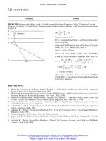
STATIC STRESSES IN MACHINE ELEMENTS 2.39
Downloaded from Digital Engineering Library @ McGraw-Hill (www.digitalengineeringlibrary.com)
Copyright © 2004 The McGraw-Hill Companies. All rights reserved.
Any use is subject to the Terms of Use as given at the website.
STATIC STRESSES IN MACHINE ELEMENTS
TABLE 2-11
Relations between strain rosette readings and principal stresses
Rosette type
Required solutions
Maximum normal
stress,
max
E
1 À
2
ð"
1
þ "
2
Þ
E
2
"
1
þ "
3
1 À
þ
1
1 þ
 E
"
1
þ "
2
þ "
3
3ð1 ÀÞ
þ
1
1 þ
Â
E
2
"
1
þ "
4
1 À
þ
1
1 þ
Â
ffiffiffiffiffiffiffiffiffiffiffiffiffiffiffiffiffiffiffiffiffiffiffiffiffiffiffiffiffiffiffiffiffiffiffiffiffiffiffiffiffiffiffiffiffiffiffiffiffiffiffiffiffiffiffiffiffiffiffiffiffi
ð"
1
À "
3
Þ
2
þ½2"
2
Àð"
1
þ "
3
Þ
2
q
ffiffiffiffiffiffiffiffiffiffiffiffiffiffiffiffiffiffiffiffiffiffiffiffiffiffiffiffiffiffiffiffiffiffiffiffiffiffiffiffiffiffiffiffiffiffiffiffiffiffiffiffiffiffiffiffiffiffiffiffiffiffiffiffiffiffiffiffiffiffiffiffiffi
"
1
À
"
1
þ "
2
þ "
3
3
2
þ
"
2
À "
3
ffiffiffi
3
p
2
s
ffiffiffiffiffiffiffiffiffiffiffiffiffiffiffiffiffiffiffiffiffiffiffiffiffiffiffiffiffiffiffiffiffiffiffiffiffiffiffiffiffiffiffiffiffiffiffiffiffi
ð"
1
À "
4
Þ
2
þ
4
3
ð"
2
À "
3
Þ
2
r
Minimum normal
stress,
min
E
1 À
2
ð"
2
þ "
1
Þ
E
2
"
1
þ "
3
1 À
À
1
1 þ
 E
"
1
þ "
2
þ "
3
3ð1 ÀÞ
À
1
1 þ
Â
E
2
"
1
þ "
4
1 À
À
1
1 þ
Â
ffiffiffiffiffiffiffiffiffiffiffiffiffiffiffiffiffiffiffiffiffiffiffiffiffiffiffiffiffiffiffiffiffiffiffiffiffiffiffiffiffiffiffiffiffiffiffiffiffiffiffiffiffiffiffiffiffiffiffiffiffi
ð"
1
À "
3
Þ
2
þ½2"
2
Àð"
1
þ "
3
Þ
2
q
ffiffiffiffiffiffiffiffiffiffiffiffiffiffiffiffiffiffiffiffiffiffiffiffiffiffiffiffiffiffiffiffiffiffiffiffiffiffiffiffiffiffiffiffiffiffiffiffiffiffiffiffiffiffiffiffiffiffiffiffiffiffiffiffiffiffiffiffiffiffiffiffiffi
"
1
À
"
1
þ "
2
þ "
3
3
2
þ
"
2
À "
3
ffiffiffi
3
p
2
s
ffiffiffiffiffiffiffiffiffiffiffiffiffiffiffiffiffiffiffiffiffiffiffiffiffiffiffiffiffiffiffiffiffiffiffiffiffiffiffiffiffiffiffiffiffiffiffiffiffi
ð"
1
À "
4
Þ
2
þ
4
3
ð"
2
À "
3
Þ
2
r
Maximum shearing
stress,
max
E
2ð1 þÞ
ð"
1
À "
2
Þ
E
2ð1 þÞ
Â
E
1 þ
Â
E
2ð1 þÞ
Â
ffiffiffiffiffiffiffiffiffiffiffiffiffiffiffiffiffiffiffiffiffiffiffiffiffiffiffiffiffiffiffiffiffiffiffiffiffiffiffiffiffiffiffiffiffiffiffiffiffiffiffiffiffiffiffiffiffiffiffiffiffi
ð"
1
À "
3
Þ
2
þ½2"
2
Àð"
1
þ "
3
Þ
2
q
ffiffiffiffiffiffiffiffiffiffiffiffiffiffiffiffiffiffiffiffiffiffiffiffiffiffiffiffiffiffiffiffiffiffiffiffiffiffiffiffiffiffiffiffiffiffiffiffiffiffiffiffiffiffiffiffiffiffiffiffiffiffiffiffiffiffiffiffiffiffiffiffiffi
"
1
À
"
1
þ "
2
þ "
3
3
2
þ
"
2
À "
3
ffiffiffi
3
p
2
s
ffiffiffiffiffiffiffiffiffiffiffiffiffiffiffiffiffiffiffiffiffiffiffiffiffiffiffiffiffiffiffiffiffiffiffiffiffiffiffiffiffiffiffiffiffiffiffiffiffi
ð"
1
À "
4
Þ
2
þ
4
3
ð"
2
À "
3
Þ
2
r
Angle from gauge 1
axis to maximum
normal stress angle,
’
p
0
1
2
tan
À1
2"
2
Àð"
1
þ "
3
Þ
"
1
À "
3
1
2
tan
À1
1
ffiffiffi
3
p
ð"
2
À "
3
Þ
"
1
À
"
1
þ "
2
þ "
3
3
2
6
6
4
3
7
7
5
1
2
tan
À1
2ð"
2
À "
3
Þ
ffiffiffi
3
p
ð"
1
À "
4
Þ
Ã
Poisson’s ratio. The author has used as symbol for Poisson’s ratio.
Source: Perry, C. C., and H. R. Lissner, The Strain Gage Primer, 2nd ed., McGraw-Hill Publishing Company, New York, p. 147, 1962.
2.40
Downloaded from Digital Engineering Library @ McGraw-Hill (www.digitalengineeringlibrary.com)
Copyright © 2004 The McGraw-Hill Companies. All rights reserved.
Any use is subject to the Terms of Use as given at the website.
STATIC STRESSES IN MACHINE ELEMENTS
Table 2-12
Singularity functions
Function Graph of f
n
ðxÞ Meaning
Concentrated moment
hx Àai
À2
¼
1 x ¼ a
0 x 6¼ a
ð
x
À1
hx Àai
À2
dx ¼hx À ai
À1
Concentrated force
hx Àai
À1
¼
1 x ¼ a
0 x 6¼ a
ð
x
À1
hx Àai
À1
dx ¼hx À ai
0
Unit step
hx Àai
0
¼
0 x < a
1 x ! a
ð
x
À1
hx Àai
0
dx ¼hx À ai
1
Rump
hx Àai
1
¼
0 x < a
x Àax! a
ð
x
À1
hx Àai
1
dx ¼
hx Àai
2
2
Parabolic
hx Àai
2
¼
0 x < a
ðx ÀaÞ
2
x ! a
ð
x
À1
hx Àai
2
dx ¼
hx Àai
3
3
STATIC STRESSES IN MACHINE ELEMENTS
2.41
Downloaded from Digital Engineering Library @ McGraw-Hill (www.digitalengineeringlibrary.com)
Copyright © 2004 The McGraw-Hill Companies. All rights reserved.
Any use is subject to the Terms of Use as given at the website.
STATIC STRESSES IN MACHINE ELEMENTS
TABLE 2-13
Summary of strain and stress equations due to different types of loads
Symbols: a ¼ major semi-axis of ellipse of area of contact, mm (in), and also radius of band of contact in case of spheres, mm (in); b ¼ minor semi-axis of ellipse of area of contact,
mm (in), and also half-bandwidth of rectangle contact between cylinders with parallel axis, mm (in); d
1
, d
2
¼ diameters of small and large spheres respectively, mm (in); E
1
,
E
2
¼ moduli of elasticities of bodies in contact respectively, GPa (psi); F ¼ load, kN (lbf); F
0
¼ðF=‘ Þ¼load per unit length, kN/m (lbf/in); k
1
, k
2
¼ material constants for
small and large solid elastic bodies in contact; L ¼ length of cylinder, m (in); p
max
¼ maximum pressure on surfaces of contact, MPa (psi);
c max
¼ maximum contact
compressive stress, MPa (psi); ¼ normal stress, also with subscripts, MPa (psi); ¼ shear stress, also with subscripts MPa (psi);
1
,
2
¼ Poisson’s ratio of materials of small
and large elastic bodies in contact respectively; ¼ approach distance along the line of action of the load between two points on the elastic bodies in contact, mm (in);
¼ hoop or circumferential or tangential stress, MPa (psi);
a
¼ axial or longitudinal stress, MPa (psi); h ¼ thickness of cylinder/vessel/shell, mm (in). Meaning of other
symbols used in this Table are given under Symbols introduced at the beginning of this Chapter.
d
o
¼
d
1
d
2
d
1
þ d
2
; d
0
o
¼
d
1
d
2
d
1
À d
2
; k
1
¼
1 À
2
1
E
1
; k
2
¼
1 À
2
2
E
2
; ¼
b
a
; e ¼
ffiffiffiffiffiffiffiffiffiffiffiffiffiffiffi
a
2
À b
2
p
a
Figure showing Type of
Applied stresses
Strain equations/Area
Maximum stress produced
loads loads Figure showing stress
x
y
z
/Approach distance
max
max
Principal stresses
1
Axial
load
F
A
000
"
x
¼ "
1
¼
E
¼
x
E
"
y
¼ "
2
¼À"
1
¼À"
x
;
"
z
¼ "
3
¼À"
1
¼À"
z
;
x
¼
max
x
2
¼
max
2
1
¼ E"
1
;
2
¼ 0;
3
¼ 0
2
Bending
load
sn
b
¼
M
b
c
I
000
"
x
¼ "
1
¼
bx
E
;
"
y
¼ "
2
¼À"
1
;
"
z
¼ "
3
¼À"
1
bx
bx
2
3
Bending
and axial
load
R
¼
F
A
þ
M
b
l
000
"
x
¼ "
1
¼
E
;
"
y
¼ "
2
¼Àv"
1
;
"
z
¼ "
3
¼Àv"
1
bx
bx
2
4
Torsion 000
M
t
r
J
¼
M
t
Z
p
¼
G
¼
r
L
1t
¼À
1c
¼
at 458 to the shaft axis
2.42
Downloaded from Digital Engineering Library @ McGraw-Hill (www.digitalengineeringlibrary.com)
Copyright © 2004 The McGraw-Hill Companies. All rights reserved.
Any use is subject to the Terms of Use as given at the website.
STATIC STRESSES IN MACHINE ELEMENTS
TABLE 2-13
Summary of strain and stress equations due to different types of loads (Cont.)
Figure showing Type of
Applied stresses
Strain equations/Area
Maximum stress produced
loads loads Figure showing stress
x
y
z
/Approach distance
max
max
Principal stresses
5
Torsion and
axial load
F
A
00
M
t
r
J
¼
M
t
Z
p
"
x
¼
x
E
and
¼
G
¼
r
L
max
¼
x
2
h
þ
1
2
ffiffiffiffiffiffiffiffiffiffiffiffiffiffiffiffiffiffi
z
x
þ 4
2
q
max
¼
1
2
ffiffiffiffiffiffiffiffiffiffiffiffiffiffiffiffiffiffi
2
x
þ 4
2
q
1;2
¼
1
2
at
þ
ffiffiffiffiffiffiffiffiffiffiffiffiffiffiffiffiffiffiffi
2
at
þ 4
2
q
6 Torsion and
bending
load
M
b
c
I
00
M
t
r
J
¼
M
t
Z
p
"
x
¼
x
E
and
¼
G
¼
r
L
max
¼
x
2
h
þ
1
2
ffiffiffiffiffiffiffiffiffiffiffiffiffiffiffiffiffiffi
z
x
þ 4
2
q
max
¼
1
2
ffiffiffiffiffiffiffiffiffiffiffiffiffiffiffiffiffiffi
2
x
þ 4
2
q
1
¼
1
2
ab
þ
ffiffiffiffiffiffiffiffiffiffiffiffiffiffiffiffiffiffiffiffi
2
ab
þ 4
2
q
¼
16
D
3
M
b
Æ
ffiffiffiffiffiffiffiffiffiffiffiffiffiffiffiffiffiffiffiffi
M
2
b
þ M
2
t
q
7
Axial, bending
and torsion
load
M
b
c
l
þ
F
A
00
M
t
r
J
¼
M
t
Z
p
¼
G
¼
r
L
max
¼
x
2
þ
max
max
¼
1
2
ffiffiffiffiffiffiffiffiffiffiffiffiffiffiffiffiffiffi
2
x
þ 4
2
q
1;2
¼
1
2
at
þ
ab
½
Æ
1
2
ffiffiffiffiffiffiffiffiffiffiffiffiffiffiffiffiffiffiffiffiffiffiffiffiffiffiffiffiffiffiffiffiffiffiffi
at
À
ab
ðÞ
2
þ4
2
q
8
Thin-walled
cylinder under
internal
pressure with
closed ends
¼
pd
2h
a
¼
pd
4h
0 0 General biaxial
"
a
¼
1
E
a
À
ðÞ
"
¼
1
E
À
a
ðÞ
x
x
2
General biaxial:
1
¼ E
"
1
À "
2
ðÞ
1 À
2
2
¼ E
"
2
À "
1
ðÞ
1 À
2
3
¼ 0
9
Thin-walled
cylinder under
internal
pressure and
axial tensile
load with
closed ends
¼
pd
2h
a
¼
pd
4h
þ
F
A
00
"
a
¼
1
E
a
À
ðÞ
"
¼
1
E
À
a
ðÞ
x
or
y
whichever
is larger
max
2
1
¼ E
"
1
À "
2
ðÞ
1 À
2
2
¼ E
"
2
À "
1
ðÞ
1 À
2
3
¼ 0
10
Thin walled
cylinder under
internal
pressure and
compressive
load with
closed ends.
¼
pd
2h
a
¼
pd
4h
À
F
A
00
"
a
¼
1
E
a
À
ðÞ
"
¼
1
E
À
a
ðÞ
x
x
2
; if
y
> 0
x
À
y
2
; if
y
< 0
1
¼ E
"
1
À "
2
ðÞ
1 À
2
2
¼ E
"
2
À "
1
ðÞ
1 À
2
3
¼ 0
2.43
Downloaded from Digital Engineering Library @ McGraw-Hill (www.digitalengineeringlibrary.com)
Copyright © 2004 The McGraw-Hill Companies. All rights reserved.
Any use is subject to the Terms of Use as given at the website.
STATIC STRESSES IN MACHINE ELEMENTS
TABLE 2-13
Summary of strain and stress equations due to different types of loads (Cont.)
Figure showing Type of
Applied stresses
Strain equations/Area
Maximum stress produced
loads loads Figure showing stress
x
y
z
/Approach distance
max
max
Principal stresses
11 Closed walled
spherical shell
under internal
pressure
¼
pd
4h
a
¼
pd
4h
0 0 Biaxial hoop stress:
Volume strain
"
¼
3pd
4hE
1 À ðÞ
12
M
t
A thin-walled
cylinder under
internal
pressure and
torsion with
closed ends
x
¼
y
¼
a
0
M
t
r
J
"
¼
1
E
À
a
ðÞ
"
a
¼
1
E
a
À
ðÞ
¼
G
¼
r
L
max
¼
À
a
2
12
¼
1
2
h
þ
a
ðÞ
Æ:
ffiffiffiffiffiffiffiffiffiffiffiffiffiffiffiffiffiffiffiffiffiffiffiffiffiffiffiffiffiffiffiffi
À
a
ðÞ
2
þ4
2
q
13
h: THICKNESS
Thick-walled
cylinder under
internal and
external
pressure with
closed ends
¼ a þ
b
r
2
where
a ¼
p
1
d
2
1
À p
0
d
2
0
d
2
0
À d
2
1
b ¼
p
1
À p
0
ðÞd
2
1
d
2
0
4 d
2
0
À d
2
1
y
¼ a À
b
r
2
-p General triaxial
"
¼
1
E
À
r
þ
a
ðÞ½
"
a
¼
1
E
a
À
þ
r
ðÞ½
À
r
2
1
¼
E 1 À
ðÞ
"
1
þ "
2
þ "
3
ðÞ½
1 À À 2
2
2
¼
E 1 À ðÞ"
2
þ "
3
þ "
1
ðÞ½
1 À À 2
2
3
¼
E 1 À ðÞ"
3
þ "
2
þ "
1
ðÞ½
1 À À 2
2
14 Hydraulic
pressure
Àp Àp Àp 0
0
2.44
Downloaded from Digital Engineering Library @ McGraw-Hill (www.digitalengineeringlibrary.com)
Copyright © 2004 The McGraw-Hill Companies. All rights reserved.
Any use is subject to the Terms of Use as given at the website.
STATIC STRESSES IN MACHINE ELEMENTS
TABLE 2-13
Summary of strain and stress equations due to different types of loads (Cont.)
Figure showing Type of
Applied stresses
Strain equations/Area
Maximum stress produced
loads loads Figure showing stress
x
y
z
/Approach distance
max
max
Principal stresses
15 ++General
case of loading
(Triaxial stress
including shear
stress)
The three principal stresses
1
;
2
and
3
are given by the three roots of the cubic equation in
3
À
þ
y
þ
x
2
À
y
þ
y
z
þ
z
x
À
2
À
2
yz
À
2
zx
À
x
y
z
þ 2
xy
yz
zx
À
x
2
yz
À
y
2
zx
À
z
2
xy
¼ 0
The direction of each principal stress is defined by the cosines of the angles it makes with 0x,0y, and 0z. The maximum shear stress
occurs in each two planes inclined at 458 to the principal stress.
The maximum shear stresses are:
max
ðÞ
1
¼
2
À
3
2
;
max
ðÞ
2
¼
3
À
1
2
;
max
ðÞ
3
¼
2
À
1
2
For details of general cases of stress, strains and direction cosines refer to Handbook and Theory of Elasticity.
16
General case of
contact of two
elastic bodies
under
compressive
load
The auxiliary angle
defines the two coefficients
p and q and is given by
¼ cos
À1
ð=Þ. p, q and
are obtained from table
given below for various
values of :
av
¼
F
ab
A ¼ ab
a ¼ p
3
4
Fk
1
þ k
2
ðÞ
1=3
; b ¼ q
3
4
Fk
1
þ k
2
ðÞ
1=3
¼ðA þBÞ¼
1
2
1
1
þ
1
0
1
þ
1
2
þ
1
0
2
¼ðB ÀAÞ¼
1
2
1
1
À
1
0
1
2
þ
"
1
2
À
1
0
2
2
þ
2
1
1
À
1
0
1
þ
1
2
À
1
0
2
cos 2
1=2
¼
9F
2
128
k
1
þ k
2
ðÞ
2
"#
1=3
c max
¼
3
2
F
ab
max
ðÞ
z¼0:63a
¼ 0:34
c max
½
1
¼
x
ðÞ¼
À2
c max
À
ð1 À2Þ
c max
b
a þb
2
¼
y
¼
À2
c max
À
ð1 À2Þ
c max
a
a þb
3
¼
z
ðÞ¼À
c max
:
ðÞ
x¼Æa
y¼0
¼
ð1 À 2Þ
c max
Â
e
2
1
e
tanh
À1
e À1
ðÞ
x¼0
y¼Æb
¼
ð1 À2Þ
c max
Â
e
2
1 À
e
tan
À1
"
, deg 10 20 30 35 40 45 50 55 60 65 70 75 80 85 90
p 6.612 3.778 2.731 2.397 2.136 1.926 1.754 1.611 1.486 1.378 1.286 1.202 1.128 1.061 1.000
q 0.319 0.408 0.493 0.530 0.567 0.604 0.641 0.678 0.717 0.750 0.802 0.845 0.893 0.944 1.000
0.851 1.220 1.453 1.550 1.637 1.709 1.772 1.828 1.875 1.912 1.944 1.967 1.985 1.996 2.000
2.45
Downloaded from Digital Engineering Library @ McGraw-Hill (www.digitalengineeringlibrary.com)
Copyright © 2004 The McGraw-Hill Companies. All rights reserved.
Any use is subject to the Terms of Use as given at the website.
STATIC STRESSES IN MACHINE ELEMENTS
TABLE 2-13
Summary of strain and stress equations due to different types of loads (Cont.)
Figure showing Type of
Applied stresses
Strain equations/Area
Maximum stress produced
loads loads Figure showing stress
x
y
z
/Approach distance
max
max
Principal stresses
17 Contact of a
solid sphere on
a solid plane
surface under
compressive
load
av
¼
F
a
2
c max
¼À
3
2
F
a
2
A ¼ a
2
a ¼ 0:721 Fd k
1
þ k
2
ðÞ½
1=3
¼ 1:78
ffiffiffiffiffiffiffiffiffiffiffiffiffiffiffiffiffiffiffiffiffiffiffiffiffiffiffiffiffiffi
2F
2
d
k
1
þ k
2
ðÞ
2
3
s
cðmaxÞ
¼
0:918 Â
F
d
2
k
1
þ k
2
ðÞ
2
"#
1=3
9
=
;
18
Contact of a
solid sphere on
solid sphere
under
compressive
load
av
¼
F
a
2
e max
¼À
3
2
F
a
2
A ¼ a
2
a ¼
3
8
Fd
0
k
1
þ k
2
ðÞ
1=3
¼
9F
2
k
1
þ k
2
ðÞ
2
8d
0
"#
1=3
cðmaxÞ
¼
24F
a
3
d
2
0
k
1
þ k
2
ðÞ
2
"#
1=3
The three principal stresses at the point of contact are:
r
¼
¼
¼
y
¼À
p
max
2
ð1 þ 2ÞÀ2ð1 þ Þ
z
ffiffiffiffiffiffiffiffiffiffiffiffiffiffiffi
a
2
þ z
2
p
þ
z
ffiffiffiffiffiffiffiffiffiffiffiffiffiffiffi
a
2
þ z
2
p
3
"#
z
¼
c
ðÞ¼Àp
max
1 À
z
3
a
2
þ z
2
ðÞ
3=2
"#
The maximum Hertz contact stress is
z max
ðÞ
z¼0
¼Àp
max
¼
c max
¼À
3F
2a
2
The maximum shear stress is
13
¼
xz
¼
p
max
2
1 À2
2
þð1 þÞ
z
ffiffiffiffiffiffiffiffiffiffiffiffiffiffiffi
a
2
þ z
2
p
À
3
2
z
ffiffiffiffiffiffiffiffiffiffiffiffiffiffiffi
a
2
þ z
2
p
3
"#
The distance from the surface of contact on the line of action of the load at which the maximum shear stress accurse z ¼ a
ffiffiffiffiffiffiffiffiffiffiffiffiffiffi
2 þ2
7 À2
r
The maximum sub-surface shear stress at z ¼ 0:63a is
max
ðÞ
z¼0:63a
¼ 0:34
c max
For principal stresses and variation of stresses along the line of action of load refer to Figure 2-28
À
max
z¼0
¼
y max
z¼0
¼À
1 þ 2
2
p
max
¼À
1 þ 2
2
c
m
13 max
¼
xz max
¼
p
max
2
1 À 2
2
þ
2
9
ð1 þÞ
ffiffiffiffiffiffiffiffiffiffiffiffiffiffiffiffiffi
2ð1 þÞ
p
19
Contact of a
solid sphere
with a spherical
socket subject
to compressive
load.
av
¼
F
a
2
c max
¼
3
2
F
a
2
a ¼ 0:721 Fd
0
0
k
1
þ k
2
ðÞ
1=3
¼ 1:04 F
2
k
1
þ k
2
ðÞ
d
0
1=3
cðmaxÞ
24
3
F
d
0
2
0
1
k
1
þ k
2
ðÞ
2
"#
1=3
2.46
Downloaded from Digital Engineering Library @ McGraw-Hill (www.digitalengineeringlibrary.com)
Copyright © 2004 The McGraw-Hill Companies. All rights reserved.
Any use is subject to the Terms of Use as given at the website.
STATIC STRESSES IN MACHINE ELEMENTS
TABLE 2-13
Summary of strain and stress equations due to different types of loads (Cont.)
Figure showing Type of
Applied stresses
Strain equations/Area
Maximum stress produced
loads loads Figure showing
stress
x
y
z
/Approach distance
max
max
Principal stresses
A ¼ 2Lb
20
Contact of a
solid cylinder
on a solid
cylinder under
compressive
load with axes
parallel.
av
¼
z
¼
F
2Lb
b ¼ 1:6
F
L
d
0
k
1
þ k
2
ðÞ
1=2
¼
2F
L
k
1
ln
d
1
b
þ 0:41
þ
k
2
ln
d
2
b
þ 0:41
cðmaxÞ
¼ 0:798
F
Ld
1
k
1
þ k
2
1=2
21 Contact of
solid cylinder
on a solid
cylinder under
compressive
load with axes
perpendicular
av
¼
z
¼
F
ab
A ¼ ab
¼ 1:41C
r
ffiffiffiffiffiffiffiffiffiffiffiffiffiffiffiffiffiffiffiffiffiffiffiffiffiffiffiffiffiffiffiffiffiffiffiffiffiffiffiffiffiffiffiffiffiffiffiffi
2F
2
2d
2
þ d
1
d
1
d
2
k
1
þ k
2
ðÞ
2
3
s
Ã
Refer to Table C
r
for
various ratios of
i
p
¼
1
d
2
1
d
1
c max
¼
s
¼À
1:5F
ab
max
ðÞ
z¼0:63a
¼ :034
c max
22 Contact of a
solid sphere
with cylindrical
groove/socket
under
compressive
load.
av
¼
z
¼
F
ab
A ¼ ab
2b ¼ 1:6
F
L
k
1
þ k
2
d
0
0
1=2
¼ 1:41C
r
ffiffiffiffiffiffiffiffiffiffiffiffiffiffiffiffiffiffiffiffiffiffiffiffiffiffiffiffiffiffiffiffiffiffiffiffiffiffiffiffiffiffiffiffiffiffiffiffi
2F
2
2d
2
À d
1
d
1
d
2
k
1
þ k
2
ðÞ
2
3
s
Ã
Refer to Table C
r
for
various ratios of
i
p
¼
1
d
1
À
1
d
2
1
d
1
cðmaxÞ
¼ 0:798
F
L
d
0
0
k
2
þ k
2
1=2
23 Contact of a
solid cylinder
with a flat
surface subject
to compressive
load
av
¼
a
¼
F
2Lb
A ¼ 2Lb
b ¼ 1:6
Fd
L
k
1
þ k
2
ðÞ
1=2
¼ 4
F
L
k
1
ln
2d
b
þ 0:41
cðmaxÞ
¼ 0:798
F
Ld
1
k
1
þ k
2
1=2
2.47
Downloaded from Digital Engineering Library @ McGraw-Hill (www.digitalengineeringlibrary.com)
Copyright © 2004 The McGraw-Hill Companies. All rights reserved.
Any use is subject to the Terms of Use as given at the website.
STATIC STRESSES IN MACHINE ELEMENTS
TABLE 2-13
Summary of strain and stress equations due to different types of loads (Cont.)
Figure showing Type of
Applied stresses
Strain equations/Area
Maximum stress produced
loads loads Figure showing stress
x
y
z
/Approach distance
max
max
Principal stresses
24 Contact of a
solid sphere
on a solid
cylinder
under
compressive
load
av
¼
z
¼
F
ab
A ¼ ab
a ¼
3
8
Fd
0
k
1
þ k
2
ðÞ
1=3
¼ 1:4C
r
ffiffiffiffiffiffiffiffiffiffiffiffiffiffiffiffiffiffiffiffiffiffiffiffiffiffiffiffiffiffiffiffiffiffiffiffiffiffiffiffiffiffiffiffiffiffiffiffiffiffiffiffi
2F
2
2d
2
þ d
1
ðÞ
d
1
d
2
k
1
þ k
2
ðÞ
2
3
s
ÃÃ
Refer to Table C
r
for
various ratios of
i
¼ 2
1
d
1
1
d
1
þ
1
d
2
c max
¼
2AF
3
d
4
0
1
k
1
þ k
2
ðÞ
2
"#
1=3
25 Cylinder
between two
flat plates
under
compressive
load
av
¼
z
¼
F
2Lb
Total deformation due to compression
of cylinder is
cy
Approach distance of two points along
the line of action of load in two plates
is ,ifE
1
¼ E
2
¼ E and
1
¼
2
¼
A ¼ 2Lb
b ¼ 1:6
Fd
L
ðk
1
þ k
2
Þ
1=2
cy
¼ 4
F
L
k
1
0:41 þln
2d
b
¼ 4
F
L
1 À
2
E
!
ln
EL
F 1 À
2
ðÞ
c max
¼ 0:798
ffiffiffiffiffiffiffiffiffiffiffiffiffiffiffiffiffiffiffiffiffiffiffiffiffi
F
Ld k
1
þ k
2
ðÞ
s
**TABLE: C
rv
values for various ratios of i
i
1.00 0.404 0.250 0.160 0.085 0.067 0.044 0.032 0.020 0.015 0.003
C
rv
1.00 0.957 0.905 0.845 0.751 0.716 0.655 0.607 0.546 0.510 0.358
ÃÃ
Source: Roark, R.J., and W. C. Young, Formulas for Stress and Strain, McGraw-Hill Publishing Company, New York, 1975.
+ Hertz. H., On the Contact of Elastic Solids, J. Math. (Crelle’s J.) vol. 92, pp 156-171, 1981
Hertz. H., On Gesammelte werke, Vol 1., p 155, Leipzig, 1895.
2.48
Downloaded from Digital Engineering Library @ McGraw-Hill (www.digitalengineeringlibrary.com)
Copyright © 2004 The McGraw-Hill Companies. All rights reserved.
Any use is subject to the Terms of Use as given at the website.
STATIC STRESSES IN MACHINE ELEMENTS
REFERENCES
1. Maleev, V. L. and J. B. Hartman, Machine Design, International Textbook Company, Scranton,
Pennsylvania, 1954.
2. Shigley, J. E., Mechanical Engineering Design , 3rd edition, McGraw-Hill Book Company, New York, 1977.
3. Lingaiah, K., and B. R. Narayana Iyengar, Machine Design Data Handbook, Vol. 1 (SI and Customary Metric
Units), Suma Publishers, Bangalore, India, 1986.
4. Lingaiah, K., Machine Design Data Handbook, Vol II (SI and Customary Metric Units), Suma Publishers,
Bangalore, India, 1986.
5. Lingaiah, K., Machine Design Data Handbook, McGraw-Hill Publishing Company, New York, 1994.
6. Ashton, J. E, J. C. Halpin and P. H. Petit, Primer on Composite Materials-Analysis, Technomic Publishing
Co., Inc., 750 Summer St., Stanford, Conn. 06901, 1969.
7. Roark, R. J., and W. C. Young, Formulas for Stress and Strain, McGraw-Hill Publishing Company, New
York, 1975.
8. Hertz, H., On the Contact of Elastic Solids, J. Math. (Crelle’s J.) Vol. 92, pp. 156–171, 1981.
9. Hertz, H., On Gesammelte werke, Vol I., p. 155, Leipzig, 1895.
10. Timoshenko, S., and J. N. Goodier, Theory of Elasticity, McGraw-Hill Book Company, New York, 1951.
BIBLIOGRAPHY
1. Black, P. H., and O. Eugene Adams, Jr., Machine Design, McGraw-Hill Book Company, New York, 1965.
2. Lingaiah, K, and B. R. Narayana Iyengar, Machine Design Data Handbook (fps units), Engineering College Co-
Operative Society, Bangalore, India, 1962.
3. Norman, C. A., E. S. Ault, and I. F. Zarobsky, Fundamentals of Machine Design, The Macmillan Company,
New York, 1951.
4. Vallance, A. E., and V. L. Doughtie, Design of Machine Members, McGraw-Hill Book Company, New York,
1951.
5. Timosheko, S., and J. N. Goodier, Theory of Elasticity, McGraw-Hill Book Company, New York, 1951.
6. Timoshenko, S., and J. M. Gere, Mechanics of Materials, Van Nostrand Reinhold Company, New York, 1972.
7. George Lubin, Editor, Handbook of Composites, Van Nostrand Reinhold Company, New York, 1982.
8. John Murphy, Reinforced Plastic Handbook, 2nd edition, Elsevier, Advanced Technology, 1998.
9. Hamcox, N. L., and R. M. Mayer, Design Data for Reinforced Plastics, Chapman and Hall, 1994.
STATIC STRESSES IN MACHINE ELEMENTS 2.49
Downloaded from Digital Engineering Library @ McGraw-Hill (www.digitalengineeringlibrary.com)
Copyright © 2004 The McGraw-Hill Companies. All rights reserved.
Any use is subject to the Terms of Use as given at the website.
STATIC STRESSES IN MACHINE ELEMENTS
CHAPTER
3
DYNAMIC STRESSES IN MACHINE
ELEMENTS
2
SYMBOLS
2;3
A area of cross-section, m
2
a, b coefficients
b width of bar or beam, m
c distance from neutral axis to extreme fibre, m
velocity of propagation of plane wave along a thin bar, m/s
c
L
velocity of propagation of plane longitudinal waves in an
infinite plate, m/s
c
T
velocity of propagation of plane transverse waves in an infinite
plate, m/s
d diameter of bar, m
E modulus of elasticity, GPa
F force or load, kN
force acting on piston due to steam or gas pressure corrected for
inertia effects of the piston and other reciprocating parts, kN
F
centrifugal force per unit volume, kN/m
3
F
c
the component of F acting along the axis of connecting rod, kN
F
d
dynamic load, kN
F
g
gas load, kN
F
i
inertia force, kN
F
ic
inertia force due to connecting rod, kN
F
ir
inertia force due to reciprocating parts of piston, kN
F
s
static load, kN
g acceleration due to gravity, 9.8066 m/s
2
h depth of bar or beam, m
height of fall of weight, m
J polar moment of inertia, m
4
(cm
4
)
k radius of gyration, m
k
p
radius of gyration, polar, m
K kinetic energy, N m
l length, m
m mass, kg
moving mass, kg
M ¼ m=A ratio of moving mass to area of cross-section of bar
M
b
bending moment, N m
3.1
Downloaded from Digital Engineering Library @ McGraw-Hill (www.digitalengineeringlibrary.com)
Copyright © 2004 The McGraw-Hill Companies. All rights reserved.
Any use is subject to the Terms of Use as given at the website.
Source: MACHINE DESIGN DATABOOK
M
t
torque, m N
n speed, rpm
n
0
speed, rps
n
0
¼ l=r ratio of length of connecting rod to radius of crank
p pressure
P power, kW
r radius of crank, m
radius of curvature of the path of motion of mass, m
the moment arm of the load, m
t time, s
u displacement in x-direction
modulus of resilience, N m/m
3
u, v, w displacement components in x, y,andz-directions respectively, m
U resilience, N m
internal elastic energy, N m
U
i
work done in case of suddenly applied load, N m
U
max
maximum internal elastic energy, N m
U
p
potential energy, N m
v velocity, m/s
V velocity of particle in the stressed zone of the bar, m/s
volume, m
3
V
0
initial velocity at the time of impact, m/s
w specific weight of material, kN/m
3
W total weight, kN
Z section modulus, m
3
(cm
3
)
angle between the crank and the centre line of connecting rod, deg
unit shear strain, rad/rad
weight density, kN/m
3
deflection/deformation, m (mm)
i
deformation/deflection under impact action, m (mm)
s
static deformation/deflection under the action of weight, m (mm)
" unit strain also with subscripts, mm/m
"
x
, "
y
, "
z
strains in x, y, and z-directions, mm/m
xy
,
yz
,
zx
shearing-strains in rectangular coordinates, rad/rad
angle between the crank and the centre line of the cylinder
measured from the head-end dead-centre position, deg
static angular deflection, deg
angle of twist, deg
i
angular deflection under impact load, deg
, Lame
´
’s constants
Poisson’s ratio
mass density, kg/m
3
normal stress (also with subscripts), MPa
i
impact stress (also with subscripts), MPa
0
initial stress at the time of impact and velocity V
0
,MPa
x
,
y
,
z
normal stress components parallel to x, y, and z-axis
shearing stress, MPa
l
time of load application, s
n
period of natural frequency, s
xy
,
yz
,
zx
shearing stress components in rectangular coordinates, MPa
! angular velocity, rad/s
Note:
s
and
s
with first subscript s designate strength properties of material used in the design which will be used and followed throughout the
book. Other factors in performance or in special aspects which are included from time to time in this book and being applicable only in their
immediate context are not given at this stage.
3.2 CHAPTER THREE
Downloaded from Digital Engineering Library @ McGraw-Hill (www.digitalengineeringlibrary.com)
Copyright © 2004 The McGraw-Hill Companies. All rights reserved.
Any use is subject to the Terms of Use as given at the website.
DYNAMIC STRESSES IN MACHINE ELEMENTS
INERTIA FORCE
Power
Velocity
Centrifugal force per unit volume
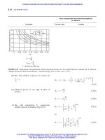
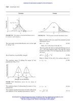
ENERGY METHOD
The internal elastic energy or work done when a
machine member is subjected to a gradually applied
load, Fig. 3.1.
The work done in case of suddenly applied load on an
elastic machine member (Fig. 3-2)
FIGURE 3-1 Plot of force against deflection in case of elas-
tic machine member subject to gradually applied load.
The relation between suddenly applied load and gra-
dually applied load on an elastic machine member to
produce the same magnitude of deflection.
P ¼
Fv
1000
SI ð3-1aÞ
where F is in newtons (N), v in m/s, and P in kW.
¼
Fv
33000
US Customary System units ð3-1bÞ
where F is in lbf, v in ft/min, and P in hp.
v ¼
2rn
12
US Customary System units (3-2a)
where r in in, v in ft/min, and n in rpm.
v ¼
2rn
60
SI ð3-2aÞ
where r in m, v in m/s, and n in rpm.
F
cv
¼
wv
2
rg
ð3-3Þ
U
¼
1
2
F ð3-4Þ
U
d
¼ F
d
ð3-5Þ
FIGURE 3-2 Plot of force against deflection in case of sud-
denly applied load on a machine member.
U
p
¼ U
d
ð3-6aÞ
F
d
¼
1
2
F ð3-6bÞ
Particular Formula
DYNAMIC STRESSES IN MACHINE ELEMENTS
3.3
Downloaded from Digital Engineering Library @ McGraw-Hill (www.digitalengineeringlibrary.com)
Copyright © 2004 The McGraw-Hill Companies. All rights reserved.
Any use is subject to the Terms of Use as given at the website.
DYNAMIC STRESSES IN MACHINE ELEMENTS
The static deformation or deflection
IMPACT STRESSES
Impact from direct load
Kinetic energy
Impact energy of a body falling from a height h
The height of fall of a body that would develop the
velocity v.
The maximum stresses produced due to fall of weight
W through the height h from rest without taking into
account the weight of shaft and collar (Fig. 3-3)
FIGURE 3-3 Striking impact of an elastic machine
member by a body of weight W falling through a height h.
The maximum deflection or deformation of shaft due
to fall of weight W through the height h from rest
neglecting the weight of shaft and collar
The stress produced due to suddenly applied load
The maximum deflection or deformation produced by
suddenly applied load
st
¼
W
k
ð3-7Þ
where k ¼ spring constant of the elastic machine
member, kN/m (lbf/in).
K ¼
Wv
2
2g
ð3-8Þ
K ¼ Wh ð3-9Þ
h ¼
v
2
2g
ð3-10Þ
i
¼
max
¼
W
A
1 þ
ffiffiffiffiffiffiffiffiffiffiffiffiffiffiffiffiffiffiffiffi
1 þ
2hEA
WL
r
"#
ð3-11aÞ
¼
st
1 þ
ffiffiffiffiffiffiffiffiffiffiffiffiffiffiffiffiffiffiffiffi
1 þ
2hEA
WL
r
"#
ð3-11bÞ
¼
st
1 þ
ffiffiffiffiffiffiffiffiffiffiffiffiffiffi
1 þ
2h
st
s
2
4
3
5
ð3-11cÞ
max
¼
i
¼
st
1 þ
ffiffiffiffiffiffiffiffiffiffiffiffiffiffiffiffiffiffiffiffi
1 þ
2hAE
WL
r
"#
ð3-12aÞ
¼
st
1 þ
ffiffiffiffiffiffiffiffiffiffiffiffiffiffi
1 þ
2h
st
s
2
4
3
5
ð3-12bÞ
ð
max
Þ
sud
¼ 2ð
max
Þ
stat
ð3-13Þ
ð
max
Þ
sud
¼ 2
st
ð3-14Þ
where subscript stat ¼ st ¼ static and
sud ¼ suddenly
Particular Formula
3.4 CHAPTER THREE
Downloaded from Digital Engineering Library @ McGraw-Hill (www.digitalengineeringlibrary.com)
Copyright © 2004 The McGraw-Hill Companies. All rights reserved.
Any use is subject to the Terms of Use as given at the website.
DYNAMIC STRESSES IN MACHINE ELEMENTS
The kinetic energy taking into account the weight of
shaft or bar and collar
The relation between , , F and W
The maximum stress due to fall of weight W through
the height h from rest taking into account the weight
of shaft/bar and collar
The maximum deflection due to fall of weight W
through the height h from rest taking into considera-
tion the weight of shaft/bar and collar
Internal elastic energy of weight W whose velocity v is
horizontal
Internal elastic energy of weight W whose velocity has
random direction
K ¼
WV
2
c
2g
1 þ
W
b
3W
ð3-15Þ
where V
c
¼ velocity of collar and weight W after
the load striking the collar, m/s.
where W
b
¼ weight of shaft or bar
F
W
¼
max
st
¼
max
st
¼ 1 þ
ffiffiffiffiffiffiffiffiffiffiffiffiffiffiffiffiffiffiffiffiffiffi
1 þ
2hAE
WL
r
"#
ð3-16aÞ
¼ 1 þ
ffiffiffiffiffiffiffiffiffiffiffiffiffiffi
1 þ
2h
st
s
2
4
3
5
ð3-16bÞ
i
¼
max
¼
W
A
1 þ
ffiffiffiffiffiffiffiffiffiffiffiffiffiffiffiffiffiffiffiffiffiffiffiffiffiffiffiffiffiffiffiffiffiffiffiffiffiffiffiffiffiffiffiffiffiffiffiffiffiffiffiffiffiffiffiffiffi
1 þ
2EAh
WL
1
1 þðW
b
=3WÞ
s
2
4
3
5
ð3-17aÞ
¼
W
A
1 þ
ffiffiffiffiffiffiffiffiffiffiffiffiffiffiffiffiffiffiffiffiffiffiffi
1 þ
2EAh
WL
r
"#
ð3-17bÞ
¼
st
1 þ
ffiffiffiffiffiffiffiffiffiffiffiffiffiffiffiffiffi
1 þ
2h
st
s
2
4
3
5
ð3-17cÞ
where ¼
1
1 þð=3Þ
and ¼
W
b
W
max
¼
WL
AE
1 þ
ffiffiffiffiffiffiffiffiffiffiffiffiffiffiffiffiffiffiffiffiffiffiffiffiffiffiffiffiffiffiffiffiffiffiffiffiffiffiffiffiffiffiffiffiffiffiffiffiffiffiffiffiffiffiffiffiffiffi
1 þ
2hEA
WL
1
1 þðW
b
=3WÞ
s
2
4
3
5
ð3-18aÞ
¼
WL
AE
1 þ
ffiffiffiffiffiffiffiffiffiffiffiffiffiffiffiffiffiffiffiffiffiffiffi
1 þ
2hAE
WL
r
"#
ð3-18bÞ
¼
st
1 þ
ffiffiffiffiffiffiffiffiffiffiffiffiffiffiffiffiffi
1 þ
2h
st
s
2
4
3
5
ð3-18cÞ
U ¼
Wv
2
2g
ð3-20Þ
U ¼
Wv
2
2g
þ W sin ð3-21Þ
where ¼ angle of velocity, v, to the horizontal
plane, deg.
Particular Formula
DYNAMIC STRESSES IN MACHINE ELEMENTS
3.5
Downloaded from Digital Engineering Library @ McGraw-Hill (www.digitalengineeringlibrary.com)
Copyright © 2004 The McGraw-Hill Companies. All rights reserved.
Any use is subject to the Terms of Use as given at the website.
DYNAMIC STRESSES IN MACHINE ELEMENTS
FIGURE 3-4 Impact by a falling body
The equation for energy balance for an impact by a
falling body (Fig. 3-4)
Another form of equation for deformation or deflec-
tion in terms of velocity v at impact
Equivalent static force that would produce the same
maximum values of deformation or deflection due
to impact
BENDING STRESS IN BEAMS DUE TO
IMPACT
Impact stress due to bending
FIGURE 3-5 Impact by a falling body on a c antilever beam
Deflection of the end of cantilever beam under impact
(Fig. 3-5)
The maximum bending stress for a cantilever beam
taking into account the total weight of beam
Fig. Fig. Fig.
Energy 3-4a 3-4b 3-4c Equation
U
p
Wðh þÞ W 0 (3-22a)
K 0
Wv
2
2g
0 (3-22b)
U 00Wðh þÞ (3-22c)
ðU
p
þ K þ UÞ
a
¼ðU
p
þ K þ UÞ
b
¼ðU
p
þ K þ UÞ
c
ð3-23Þ
max
¼
st
1 þ
ffiffiffiffiffiffiffiffiffiffiffiffiffiffiffiffi
1 þ
v
2
g
st
s
0
@
1
A
ð3-24Þ
F
eq
¼ W 1 þ
ffiffiffiffiffiffiffiffiffiffiffiffiffiffi
1 þ
2h
st
s
0
@
1
A
¼ W 1 þ
ffiffiffiffiffiffiffiffiffiffiffiffiffiffiffiffi
1 þ
v
2
g
st
s
0
@
1
A
ð3-25Þ
ð
b
Þ
max
¼
bi
¼
Wlc
I
1 þ
ffiffiffiffiffiffiffiffiffiffiffiffiffiffiffiffiffiffiffi
1 þ
6hEI
Wl
3
r
"#
ð3-26aÞ
¼
Wlc
I
1 þ
ffiffiffiffiffiffiffiffiffiffiffiffiffiffi
1 þ
2h
st
s
2
4
3
5
ð3-26bÞ
¼ð
b
Þ
st
1 þ
ffiffiffiffiffiffiffiffiffiffiffiffiffiffi
1 þ
2h
st
s
0
@
1
A
ð3-26cÞ
where ð
b
Þ
st
¼
Wlc
I
¼
M
b
c
I
¼
M
b
Z
b
:
max
¼
st
1 þ
ffiffiffiffiffiffiffiffiffiffiffiffiffiffi
1 þ
2h
st
s
0
@
1
A
ð3-27Þ
ð
b
Þ
max
¼ð
b
Þ
st
1 þ
2h
st
ð3-28Þ
where ¼
m
b
m
¼
W
b
W
and ¼
1
1 þð33=140Þ
Particular Formula
3.6 CHAPTER THREE
Downloaded from Digital Engineering Library @ McGraw-Hill (www.digitalengineeringlibrary.com)
Copyright © 2004 The McGraw-Hill Companies. All rights reserved.
Any use is subject to the Terms of Use as given at the website.
DYNAMIC STRESSES IN MACHINE ELEMENTS
The maximum deflection at the end of a cantilever
beam due to fall of weight W through the height h
from rest taking into consideration the weight of beam
The maximum bending stress for a simply supported
beam due to fall of a load/weight W from a height h
at the midspan of the beam taking into account the
total weight of the beam (Fig. 3-6)
FIGURE 3-6 Simply supported beam
The maximum deflection for a simply supported beam
due to fall of a weight W from a height h at the mid-
span of the beam taking into account the weight of
beam. (Fig. 3-6)
TORSION OF BEAM/BAR DUE TO IMPACT
(Fig. 3-7)
The equation for maximum shear stress in the bar due
to impact load at a radius r of a falling weight W from
a height h neglecting the weight of bar
FIGURE 3-7 Twist of a beam/bar
max
¼
st
1 þ
ffiffiffiffiffiffiffiffiffiffiffiffiffiffiffiffiffi
1 þ
2h
st
s
2
4
3
5
ð3-28aÞ
ð
b
Þ
max
¼ð
b
Þ
st
1 þ
ffiffiffiffiffiffiffiffiffiffiffiffiffiffiffiffiffiffiffiffiffiffiffiffiffiffiffiffiffiffiffiffiffiffiffiffiffiffiffiffiffiffiffiffiffiffiffiffiffi
1 þ
2h
st
1
1 þð17=35Þ
s
2
4
3
5
ð3-29aÞ
¼ð
b
Þ
st
1 þ
ffiffiffiffiffiffiffiffiffiffiffiffiffiffiffiffiffi
1 þ
2h
st
s
2
4
3
5
ð3-29bÞ
where ¼
1
1 þð17=35Þ
and ¼
W
b
W
max
¼
st
1 þ
ffiffiffiffiffiffiffiffiffiffiffiffiffiffiffiffiffi
1 þ
2h
st
s
2
4
3
5
ð3-30Þ
max
¼
st
1 þ
ffiffiffiffiffiffiffiffiffiffiffiffiffiffiffiffi
1 þ
2h
r
st
s
2
4
3
5
ð3-31Þ
FIGURE 3-8 Displacements due to forces acting on an ele-
ment of an elastic media.
Particular Formula
DYNAMIC STRESSES IN MACHINE ELEMENTS
3.7
Downloaded from Digital Engineering Library @ McGraw-Hill (www.digitalengineeringlibrary.com)
Copyright © 2004 The McGraw-Hill Companies. All rights reserved.
Any use is subject to the Terms of Use as given at the website.
DYNAMIC STRESSES IN MACHINE ELEMENTS
The equation for angular deflection or angular twist
of bar due to impact load W at radius r and falling
through a height h neglecting the weight of bar
LONGITUDINAL STRESS-WAVE IN
ELASTIC MEDIA (Fig. 3-8)
One-dimensional stress-wave equation in elastic
media (Fig. 3-8)
For velocity of propagation of longitudinal stress-
wave in elastic media
The solution of stress-wave Eq. (3-33a)
The value of circular frequency p
The frequency
LONGITUDINAL IMPACT ON A LONG
BAR
The velocity of particle in the compression zone
The uniform initial compressive stress on the free end
of a bar (Fig. 3-9)
The variation of stress at the end of bar at any time t
max
¼
st
1 þ
ffiffiffiffiffiffiffiffiffiffiffiffiffiffiffiffi
1 þ
2h
r
st
s
2
4
3
5
ð3-32Þ
@
2
u
@t
2
¼ c
2
@
2
u
@x
2
ð3-33aÞ
where c ¼
ffiffiffiffiffiffi
Eg
s
¼
ffiffiffiffi
E
s
ð3-33bÞ
¼ velocity of propagation of stress
waves, m/s:
Refer to Table 3-1.
x ¼
A sin
p
c
x þ B cos
p
c
x
ðc sin pt þ D cos ptÞð3-34Þ
where A, B, C and D are arbitrary constants
which can be found from initial or boundary
condition of the problem.
p ¼
nc
l
¼
n
l
ffiffiffiffiffiffi
Eg
s
¼
n
l
ffiffiffiffi
E
s
ð3-35aÞ
where n is an integer ¼ 1; 2; 3;
f ¼
p
2
¼
n
2l
ffiffiffiffi
E
s
¼
c
ð3-35bÞ
where ¼ wave length ¼ 2l=n, c ¼ speed of
sound or stress wave velocity, m/s.
V ¼
ffiffiffiffiffiffiffi
g
E
r
¼
ffiffiffiffiffiffi
E
p
ð3-36Þ
0
¼ V
0
ffiffiffiffiffiffiffi
E
g
s
¼ V
0
ffiffiffiffiffiffi
E
p
ð3-37Þ
where V
0
¼ initial velocity of the moving weight/
mass at the time of impact, m/s.
¼
0
exp À
ffiffiffiffiffiffi
E
p
M
t
0 < t <
2l
c
ð3-38Þ
Particular Formula
3.8 CHAPTER THREE
Downloaded from Digital Engineering Library @ McGraw-Hill (www.digitalengineeringlibrary.com)
Copyright © 2004 The McGraw-Hill Companies. All rights reserved.
Any use is subject to the Terms of Use as given at the website.
DYNAMIC STRESSES IN MACHINE ELEMENTS
The equations of motion in terms of t hree displace-
ment components assuming that there are no body
forces.
FIGURE 3-9 Prismatic bar subject to suddenly applied
uniform compressive stress
Dilatational and distortional waves in
isotropic elastic media
From the classical theory of elasticity equations for
irrotational or dilatational waves
Equations for distortional waves
Equations (3-40) to (3-41) are one-dimensional stress
wave equations of the form
The velocity of stress wave propagation for the case of
no rotation
ð þ GÞ
@"
@x
þ Gr
2
u ¼
@
2
u
@t
2
ð3-39aÞ
ð þ GÞ
@"
@y
þ Gr
2
v ¼
@
2
v
@t
2
ð3-39bÞ
ð þ GÞ
@"
@z
þ Gr
2
w ¼
@
2
w
@t
2
ð3-39cÞ
where
" ¼ "
x
þ "
y
þ "
z
r¼
@
2
@x
2
þ
@
2
@y
2
þ
@
2
@z
2
¼ the Laplacian operator
¼
E
ð1 þ Þð1 À 2Þ
and
¼ G ¼
E
2ð1 þ Þ
are Lam
ee’s constants
@
2
u
@t
2
¼
þ 2G
r
2
u ð3-40aÞ
@
2
v
@t
2
¼
þ 2G
r
2
v ð3-40bÞ
@
2
w
@t
2
¼
þ 2G
r
2
w ð3-40cÞ
@
2
u
@t
2
¼
G
r
2
u ð3-41aÞ
@
2
v
@t
2
¼
G
r
2
v ð3-41bÞ
@
2
w
@t
2
¼
G
r
2
w ð3-41cÞ
@
2
@t
2
¼ a
2
r
2
ð3-42Þ
a ¼ c
1
¼
ffiffiffiffiffiffiffiffiffiffiffiffiffiffiffi
þ 2G
s
¼
ffiffiffiffiffiffiffiffiffiffiffiffiffiffiffiffiffiffiffiffiffiffiffiffiffiffiffiffiffiffiffiffiffiffi
Eð1 À Þ
ð1 þ Þð1 À 2Þ
s
ð3-43Þ
Particular Formula
DYNAMIC STRESSES IN MACHINE ELEMENTS
3.9
Downloaded from Digital Engineering Library @ McGraw-Hill (www.digitalengineeringlibrary.com)
Copyright © 2004 The McGraw-Hill Companies. All rights reserved.
Any use is subject to the Terms of Use as given at the website.
DYNAMIC STRESSES IN MACHINE ELEMENTS
The velocity of stress wave propagation for the case of
zero volume change
The ratio of c
1
to c
2
The velocity of stress wave propagation for a trans-
verse stress wave, i.e. distortional wave in an infinite
plate
The velocity of stress wave propagation for plane
longitudinal stress wave in case of an infinite plate
TORSIONAL IMPACT ON A BAR
Equation of motion for torsional impact on a bar
(Fig. 3-10)
Torsional wave propagation in a bar subjected to
torsion.
For velocity of propagation of torsional stress-wave
in an elastic bar
FIGURE 3-10 Torsional impact on a uniform bar showing
torque on two faces of an element
The angular velocity of the end of a bar subject to tor-
sion relative to the unstressed region
The shear stress from Eq. (3-50)
The initial shear stress, if the rotating body strikes the
end of the bar with an angular velocity !
0
a ¼ c
2
¼
ffiffiffiffi
G
s
¼
ffiffiffiffiffiffiffiffiffiffiffiffiffiffiffiffiffiffiffiffi
E
2ð1 À Þ
s
ð3-44Þ
c
1
c
2
¼
ffiffiffiffiffiffiffiffiffiffiffiffiffiffiffiffiffi
2ð1 À Þ
ð1 À 2Þ
s
¼
ffiffiffi
3
p
for Poisson’s ratio of ¼ 0:25 ð3-45Þ
c
T
¼
ffiffiffiffi
G
s
¼
ffiffiffiffiffiffiffiffiffiffiffiffiffiffiffiffiffiffiffiffi
E
2ð1 þ Þ
s
ð3-46Þ
c
L
¼
ffiffiffiffiffiffiffiffiffiffiffiffiffiffiffiffiffiffiffiffiffiffi
4Gð þ GÞ
ð þ 2GÞ
s
¼
ffiffiffiffiffiffiffiffiffiffiffiffiffiffiffiffiffiffiffi
E
ð1 À
2
Þ
s
ð3-47Þ
@
2
@t
2
¼ c
2
t
@
2
@x
2
ð3-48Þ
c
t
¼
ffiffiffiffiffiffi
Gg
s
¼
ffiffiffiffi
G
s
ð3-49Þ
Refer to Table 3-1.
FIGURE 3-11 Torsional striking impact
! ¼
t
¼
2
t
d
ffiffiffiffiffiffi
G
p
t
t
¼
2
t
d
ffiffiffiffiffiffi
G
p
ð3-50Þ
¼
!d
2
ffiffiffiffiffiffi
G
p
ð3-51aÞ
0
¼
!
0
d
2
ffiffiffiffiffiffi
G
p
ð3-51bÞ
Particular Formula
3.10 CHAPTER THREE
Downloaded from Digital Engineering Library @ McGraw-Hill (www.digitalengineeringlibrary.com)
Copyright © 2004 The McGraw-Hill Companies. All rights reserved.
Any use is subject to the Terms of Use as given at the website.
DYNAMIC STRESSES IN MACHINE ELEMENTS
The maximum shear stress for the case of a shaft fixed
or attached to a very large mass/weight at one end and
suddenly applied rotational load at the other end by
means of some mechanical device such as a jaw
clutch (Fig. 3-11)
FIGURE 3-12 A striking rotating weight with mass-
moment of inertia I rotating at !
0
engages with one end of
shaft and the other end of shaft fixed to a mass-moment of
inertia I
f
The more accurate equation for the
max
which is
based on stress wave propagation
The initial/maximum (
i
¼
max
) shear stress for the
case of a system shown in Fig. 3-12
A similar equation to Eq. (3-54) for maximum stress
for longitudinal impact
Accurate maximum stress for longitudinal impact
stress based on stress wave propagation as suggested
by Prof. Burr
Accurate maximum stress for torsional impact shear
stress based on stress-wave propagation as suggested
by Prof. Burr
max
¼
0
ffiffiffiffiffiffiffiffiffiffiffiffiffiffiffiffiffiffiffiffiffiffiffi
1
1
1 þ
3
0
@
1
A
v
u
u
u
t
2
6
6
4
3
7
7
5
¼
0
ffiffiffiffi
r
"#
ð3-52Þ
where ¼
I
b
I
:
I
b
¼ mass moment of inertia of bar ¼ m
b
d
2
8
I ¼ mass moment of inertia of striking rotating weight
I
b
and I correspond to W
b
and W of the weight of the
bar and the rotating mass or weight respectively.
max
¼
0
1 þ
ffiffiffiffiffiffiffiffiffiffiffi
1
þ
2
3
s
2
4
3
5
ð3-53Þ
i
¼
max
¼
0
ffiffiffiffiffiffiffiffiffiffiffiffiffiffiffiffiffiffiffiffiffiffiffiffiffiffi
ð1 þ Þ
ð1 þ þ Þ
s
ð3-54Þ
where ¼
I
b
I
;¼
I
I
f
and I
b
¼ Jl:
i
¼
max
¼
0
ffiffiffiffiffiffiffiffiffiffiffiffiffiffiffiffiffiffiffiffiffiffiffiffiffiffi
ð1 þ Þ
ð1 þ þ Þ
s
ð3-55Þ
where ¼
W
b
W
¼
m
b
m
and ¼
m
m
f
i
¼
max
¼
0
1:1 þ
ffiffiffiffiffiffiffiffiffiffiffiffiffiffiffiffiffiffiffiffiffiffiffiffiffiffi
ð1 þ Þ
ð1 þ þ Þ
s
2
4
3
5
ð3-56Þ
i
¼
max
¼
0
1:1 þ
ffiffiffiffiffiffiffiffiffiffiffiffiffiffiffiffiffiffiffiffiffiffiffiffiffiffi
ð1 þ Þ
ð1 þ þ Þ
s
2
4
3
5
ð3-57Þ
Particular Formula
DYNAMIC STRESSES IN MACHINE ELEMENTS
3.11
Downloaded from Digital Engineering Library @ McGraw-Hill (www.digitalengineeringlibrary.com)
Copyright © 2004 The McGraw-Hill Companies. All rights reserved.
Any use is subject to the Terms of Use as given at the website.
DYNAMIC STRESSES IN MACHINE ELEMENTS
INERTIA IN COLLISION OF ELASTIC
BODIES
When a body having weight W strikes another body
that has a weight W
0
, impact energy Wh is reduced
to nWh, according to law of collision of two perfectly
inelastic bodies, the formula for the value of n
RESILIENCE
The expression for resilience in compression or
tension
The modulus of resilience
The area under the stress-strain curve up to yielding
point represents the modulus of resilience (Fig. 1.1)
The resilience in bending
The modulus of resilience in bending
Resilience in direct shear
The modulus of resilience in direct shear
Resilience in torsion
The modulus of resilience in torsion
The equation for strain energy due to shear in bending
The modulus of resilience due to shear in bending
n ¼
1 þ am
ð1 þ bmÞ
2
ð3-58Þ
where m ¼
W
0
W
; a and b are taken from Table 3-3
U ¼
2
2
V
E
¼
1
2
2
AL
E
ð3-59Þ
u ¼
2
2E
ð3-60Þ
u ¼
1
2
" ð3-61Þ
U
b
¼
k
c
2
2
b
AL
6E
ð3-62Þ
u
b
¼
k
c
2
2
b
6E
ð3-63Þ
where ðk=cÞ
2
¼
1
3
for rectangular cross-section
¼
1
4
for circular section
c ¼ distance from extreme fibre to
neutral axis
U
¼
2
e
V
2G
ð3-64Þ
u
¼
2
e
2G
ð3-65Þ
U
¼
2
e
AL
2G
k
0
c
2
ð3-66Þ
where k
0
¼
ffiffiffiffiffiffiffiffiffiffiffiffiffiffiffiffiffiffi
D
2
1
À D
2
0
q
=8 and c ¼
1
2
D
0
for hollow
shaft.
u
¼
2
e
2G
k
0
c
2
ð3-67Þ
U
b
¼
ð
l
0
k
F
2
2GA
dx ð3-68Þ
u
b
¼
k
2
e
2G
ð3-69Þ
Particular Formula
3.12 CHAPTER THREE
Downloaded from Digital Engineering Library @ McGraw-Hill (www.digitalengineeringlibrary.com)
Copyright © 2004 The McGraw-Hill Companies. All rights reserved.
Any use is subject to the Terms of Use as given at the website.
DYNAMIC STRESSES IN MACHINE ELEMENTS
The equation for shear or distortional strain energy
per unit volume associated with distortion, without
change in volume
The equation for dilatational or volumetric strain
energy per unit volume without distortion, only a
change in volume
For maximum resilience per unit volume (i.e., for
modulus of resilience), resilience in tension for var-
ious engineering materials and coefficients a and b;
velocity of propagation c and c
t
.
U
¼
1
6G
½
2
1
þ
2
2
þ
2
3
Àð
1
2
þ
2
3
þ
3
1
Þ
ð3-70aÞ
¼
1
12G
½ð
1
À
2
Þ
2
þð
2
À
3
Þ
2
þð
3
À
1
Þ
2
ð3-70bÞ
U
v
¼
ð1 À 2Þ
6E
½ð
1
þ
2
þ
3
Þ
2
ð3-71Þ
Refer to Tables 3-1 to 3-4.
Particular Formula
TABLE 3-1
Longitudinal velocity of longitudinal wave c and torsional wave c
t
propagation in elastic media
Density
Modulus of
elasticity, E
Modulus of
rigidity, G
c ¼
ffiffiffiffi
E
s
¼
ffiffiffiffiffiffi
Eg
s
#
c
t
¼
ffiffiffiffi
G
s
¼
ffiffiffiffiffiffi
Gg
s
#
Material g/cm
3
lb
m
/in
3
kN/m
3
GPa Mpsi GPa Mpsi m/s ft/s m/s ft/s
Aluminum alloy 2.71 0.098 26.6 71.0 10.3 26.2 3.8 5116 16785 3110 10466
Brass 8.55 0.309 83.9 106.2 15.4 40.1 5.82 3523 11560 2165 7106
Carbon steel 7.81 0.282 76.6 206.8 30.0 79.3 11.5 5145 16887 3200 10485
Cast iron, gray 7.20 0.260 70.6 100.0 14.5 41.4 6.0 3727 12223 2407 7865
Copper 8.91 0.320 87.4 118.6 17.7 44.7 6.49 3648 12176 2240 7373
Glass 2.60 0.094 25.5 46.2 6.7 18.6 2.7 4214 13823 2675 8775
Lead 11.38 0.411 111.6 36.5 5.3 13.1 1.9 1796 5879 1073 3520
Inconel 8.42 0.307 83.3 213.7 31.0 75.8 11.0 5016 16452 2987 9800
Stainless steel 7.75 0.280 76.0 190.3 27.6 73.1 10.6 4955 15972 3071 10074
Tungsten 18.82 0.680 184.6 344.7 50.0 137.9 20.0 4279 14039 2707 8880
#
Note: ¼ Mass density, g/cm
3
(lb
m
/in
3
), ¼ weight density (specific weight), kN/m
3
(lbf/in
3
), g ¼ 9:8066 m/s
2
in SI units, g ¼ 980 in=s
2
¼ 32:2ft=s
2
in fps units.
DYNAMIC STRESSES IN MACHINE ELEMENTS 3.13
Downloaded from Digital Engineering Library @ McGraw-Hill (www.digitalengineeringlibrary.com)
Copyright © 2004 The McGraw-Hill Companies. All rights reserved.
Any use is subject to the Terms of Use as given at the website.
DYNAMIC STRESSES IN MACHINE ELEMENTS
TABLE 3-2
Maximum resilience per unit volume (2, 1)
Type of loading Modulus of resilience, J (in lbf)
Tension or compression
2
e
2E
Shear, simple transverse
2
e
2G
Bending in beams
With simply supported ends:
Concentrated center load and rectangular cross-section
2
e
18E
Concentrated center load and circular cross-section
2
e
24E
Concentrated center load and I-beam section
3
2
e
32E
Uniform load and rectangular section
4
2
e
45E
Uniform-strength beam, concentrated load, and rectangular section
2
e
6E
Fixed at both ends:
Concentrated load and rectangular cross-section
2
e
18E
Uniform load and rectangular cross-section
2
e
30E
Cantilever beam:
End load and rectangular cross-section
2
e
18E
Uniform load and rectangular cross-section
2
e
30E
Torsion
Solid round bar
2
e
4G
Hollow round bar with D
0
greater than D
i
1 þ
D
i
D
o
2
2
4G
Springs
Laminated with flat leaves of uniform strength
2
e
6E
Flat spiral with rectangular section
2
e
24E
Helical with round section and axial load
2
e
4G
Helical with round section and axial twist
2
e
8E
Helical with rectangular section and axial twist
2
e
6E
Sources: K. Lingaiah and B. R. Narayana Iyengar, Machine Design Data Handbook,VolI(SI and Customary Metric Units), Suma Publishers,
Bangalore, India, 1986; K. Lingaiah, Machine Design Data Hand book, Vol II (SI and Customary Metric Units), Suma Publishers, Bangalore, India,
1986; V. L. Maleev and J. B. Hartman, Machine Design, International Textbook Company, Scranton, Pennsylvania, 1954.
3.14 CHAPTER THREE
Downloaded from Digital Engineering Library @ McGraw-Hill (www.digitalengineeringlibrary.com)
Copyright © 2004 The McGraw-Hill Companies. All rights reserved.
Any use is subject to the Terms of Use as given at the website.
DYNAMIC STRESSES IN MACHINE ELEMENTS