Machine Design Databook Episode 2 part 5 docx
Bạn đang xem bản rút gọn của tài liệu. Xem và tải ngay bản đầy đủ của tài liệu tại đây (747.92 KB, 40 trang )
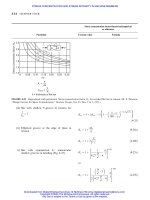
TABLE 18-35
Machine screw heads—pan, hexagon, truss, and 1008 Flat heads
Pan head Hexagon head
Height Height
of of Height
Head slotted Width Depth recessed Head of Width Depth
Max diam, head, of slot, of slot, head diam, head, of slot, of slot,
Nominal diam max, max, min, min, Radius max, max, max, min, min,
size DAHJ TROAHJ T
No. 2 0.086 0.167 0.053 0.023 0.023 0.035 0.062 0.125 0.050
No. 3 0.099 0.193 0.060 0.027 0.027 0.037 0.071 0.187 0.055
No. 4 0.112 0.219 0.068 0.031 0.030 0.042 0.080 0.187 0.060 0.031 0.025
No. 5 0.125 0.245 0.075 0.035 0.032 0.044 0.089 0.187 0.070 0.035 0.030
No. 6 0.138 0.270 0.082 0.039 0.038 0.046 0.097 0.250 0.080 0.039 0.033
No. 8 0.164 0.322 0.096 0.045 0.043 0.052 0.115 0.250 0.110 0.045 0.052
No. 10 0.190 0.373 0.110 0.050 0.050 0.061 0.133 0.312 0.120 0.050 0.057
No. 12 0.216 0.425 0.125 0.056 0.060 0.078 0.151 0.312 0.155 0.056 0.077
1
4
0.250 0.492 0.144 0.064 0.070 0.087 0.175 0.375 0.190 0.064 0.083
5
16
0.3125 0.615 0.178 0.072 0.092 0.099 0.218 0.500 0.230 0.072 0.100
3
8
0.375 0.740 0.212 0.081 0.113 0.143 0.261 0.562 0.295 0.081 0.131
THREADED FASTENERS AND SCREWS FOR POWER TRANSMISSION
18.53
Downloaded from Digital Engineering Library @ McGraw-Hill (www.digitalengineeringlibrary.com)
Copyright © 2004 The McGraw-Hill Companies. All rights reserved.
Any use is subject to the Terms of Use as given at the website.
THREADED FASTENERS AND SCREWS FOR POWER TRANSMISSION
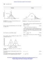
TABLE 18-35
Machine screw heads—pan, hexagon, truss, and 1008 Flat heads (Cont.)
Truss head 1008 flat head
Height Height
of of Height
Head slotted Width Depth recessed Head of Width Depth
Max diam, head, of slot, of slot, head diam, head, of slot, of slot,
Nominal diam max, max, min, min, Radius max, max, max, min, min,
size DAHJ TROAHJ T
No. 2 0.086 0.194 0.053 0.023 0.022 0.129
No. 3 0.099 0.226 0.061 0.027 0.026 0.151
No. 4 0.112 0.257 0.069 0.031 0.030 0.169 0.225 0.048 0.031 0.017
No. 5 0.125 0.289 0.078 0.035 0.034 0.191
No. 6 0.138 0.321 0.086 0.039 0.037 0.211 0.279 0.060 0.039 0.022
No. 8 0.164 0.384 0.102 0.045 0.045 0.254 0.332 0.072 0.045 0.027
No. 10 0.190 0.448 0.118 0.050 0.053 0.283 0.385 0.083 0.050 0.031
No. 12 0.216 0.511 0.134 0.056 0.061 0.336
1
4
0.250 0.573 0.150 0.064 0.070 0.375 0.507 0.110 0.064 0.042
5
16
0.3125 0.698 0.183 0.072 0.085 0.457 0.635 0.138 0.072 0.053
3
8
0.375 0.823 0.215 0.081 0.100 0.538 0.762 0.165 0.081 0.064
7
16
0.4375 0.948 0.248 0.081 0.116 0.619
1
2
0.500 1.073 0.280 0.091 0.131 0.701
9
16
0.5625 1.198 0.312 0.102 0.146 0.783
5
8
0.625 1.323 0.345 0.116 0.162 0.863
3
4
0.750 1.573 0.410 0.131 0.182 1.024
Note: Radius of fillet at base of truss- and pan-head machine screws shall not exceed one-half the pitch of the screw thread.
Truss-, pan-, and 1008 flat-head machine screws may be furnished with cross-recessed heads.
Hexagon-head machine screws are usually not slotted; the slot is optional. Also optional is an upset-head type for hexagon-head machine screws of
sizes 4, 5, 8, 12, and
1
4
in.
18.54 CHAPTER EIGHTEEN
Downloaded from Digital Engineering Library @ McGraw-Hill (www.digitalengineeringlibrary.com)
Copyright © 2004 The McGraw-Hill Companies. All rights reserved.
Any use is subject to the Terms of Use as given at the website.
THREADED FASTENERS AND SCREWS FOR POWER TRANSMISSION
TABLE 18-36
Machine-screw heads—binding head
Total Diam Depth
Head height Width Depth Height of of
Max diam, of head, of slot, of slot, of oval, undercut,
a
undercut,
Nominal diam max, max, min, min, max, min, min,
size DA O J T F U X
No. 2 0.086 0.181 0.046 0.023 0.024 0.018 0.124 0.005
No. 3 0.099 0.208 0.054 0.027 0.029 0.022 0.143 0.006
No. 4 0.112 0.235 0.063 0.031 0.034 0.025 0.161 0.007
No. 5 0.125 0.263 0.071 0.035 0.039 0.029 0.180 0.009
No. 6 0.138 0.290 0.080 0.039 0.044 0.032 0.199 0.010
No. 8 0.164 0.344 0.097 0.045 0.054 0.039 0.236 0.012
No. 10 0.190 0.399 0.114 0.050 0.064 0.045 0.274 0.015
No. 12 0.216 0.454 0.130 0.056 0.074 0.052 0.311 0.018
1
4
0.250 0.513 0.153 0.064 0.088 0.061 0.360 0.021
5
16
0.3125 0.641 0.193 0.072 0.112 0.077 0.450 0.027
3
8
0.375 0.769 0.234 0.081 0.136 0.094 0.540 0.034
a
Use of undercut is optional.
Note: Binding-head machine screws may be furnished with cross-recessed heads.
THREADED FASTENERS AND SCREWS FOR POWER TRANSMISSION 18.55
Downloaded from Digital Engineering Library @ McGraw-Hill (www.digitalengineeringlibrary.com)
Copyright © 2004 The McGraw-Hill Companies. All rights reserved.
Any use is subject to the Terms of Use as given at the website.
THREADED FASTENERS AND SCREWS FOR POWER TRANSMISSION
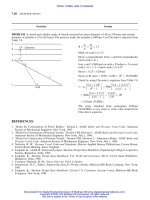
TABLE 18-37
Slotted-head cap screws
28
Fillister head Flat head Round head
Nominal
size Width Height Total Depth Height Depth Height Depth
(body of Head of height of Head of of Head of of
diam, slot diam, head, of head, slot, diam, head slot, diam, head, slot,
max) min, max, max, max, min, max, average, min, max, max, min,
D J AHOTAHTAHT
1
4
0.064 0.375 0.172 0.216 0.077 0.500 0.140 0.046 0.437 0.191 0.097
3
16
0.072 0.437 0.203 0.253 0.090 0.625 0.176 0.057 0.562 0.246 0.126
3
8
0.081 0.562 0.250 0.314 0.113 0.750 0.210 0.069 0.625 0.273 0.135
7
16
0.081 0.625 0.297 0.368 0.133 0.8125 0.210 0.069 0.750 0.328 0.167
1
2
0.091 0.750 0.328 0.412 0.148 0.875 0.210 0.069 0.812 0.355 0.179
9
16
0.102 0.812 0.375 0.466 0.169 1.000 0.245 0.080 0.937 0.410 0.208
5
8
0.116 0.875 0.422 0.521 0.190 1.125 0.281 1.092 1.000 0.438 0.220
3
4
0.131 1.000 0.500 0.612 0.233 1.375 0.352 0.115 0.125 0.547 0.227
7
8
0.147 1.125 0.594 0.720 0.264 1.625 0.423 0.139
1 0.166 1.312 0.656 0.802 0.292 1.875 0.494 0.162
1
1
8
0.178————2.0620.5290.173
1
1
4
0.193————2.3120.6000.197
1
3
8
0.208————2.5620.6650.220
1
1
2
0.240————2.8120.7420.244
18.56 CHAPTER EIGHTEEN
Downloaded from Digital Engineering Library @ McGraw-Hill (www.digitalengineeringlibrary.com)
Copyright © 2004 The McGraw-Hill Companies. All rights reserved.
Any use is subject to the Terms of Use as given at the website.
THREADED FASTENERS AND SCREWS FOR POWER TRANSMISSION
TABLE 18-38
Socket-head cap screws
Hexagon
a
Fluted socket
Socket Width
Head width Socket Socket of
Body Head Head side across diam diam socket
diam, diam, height height, flats, Number minor, major, land,
Nominal max, max, max, max, min, of min, min, max,
size DAHS J flutes KMN
No. 0 0.060 0.096
No. 1 0.073 0.118
No. 2 0.0860 0.140 0.086 0.0803
1
16
6 0.063 0.073 0.016
No. 3 0.0990 0.161 0.099 0.0923
5
64
6 0.080 0.097 0.022
No. 4 0.1120 0.183 0.112 0.1043
5
64
6 0.080 0.097 0.022
No. 5 0.1250 0.205 0.125 0.1163
3
32
6 0.096 0.113 0.025
No. 6 0.1380 0.226 0.138 0.1284
3
32
6 0.096 0.113 0.025
No. 8 0.1640 0.270 0.164 0.1522
1
8
6 0.126 0.147 0.032
No. 10 0.1900
5
16
0.190 0.1765
5
32
6 0.161 0.186 0.039
No. 12 0.2160
11
32
0.216 0.2005
5
32
6 0.161 0.186 0.039
1
4
0.2500
3
8
1
4
0.2317
3
16
6 0.188 0.219 0.050
5
16
0.3125
7
16
5
16
0.2894
7
32
6 0.219 0.254 0.060
3
8
0.3750
9
16
3
8
0.3469
5
16
6 0.316 0.377 0.092
7
16
0.4375
5
8
7
16
0.4046
5
16
6 0.316 0.377 0.092
1
2
0.5000
1
4
1
2
0.4620
3
8
6 0.383 0.460 0.112
9
16
0.5625
13
16
9
16
0.5196
3
8
6 0.383 0.460 0.112
5
8
0.6250
7
8
5
8
0.5771
1
2
6 0.506 0.601 0.138
3
4
0.7500 1
3
4
0.6920
9
16
6 0.531 0.627 0.149
7
8
0.8750 1
1
8
7
8
0.8069
9
16
6 0.600 0.705 0.168
1 1.0000 1
5
16
1 0.9220
5
8
6 0.681 0.797 0.189
1
1
8
1.1250 1
1
2
1
1
8
1.0372
3
4
6 0.824 0.966 0.231
1
1
4
1.2500 1
3
4
1
1
4
1.1516
3
4
6 0.824 0.966 0.231
1
3
8
1.3750 1
7
8
1
3
8
1.2675
3
4
6 0.824 0.966 0.231
1
1
2
1.5000 2 1
1
2
1.3821 1 6 1.003 1.271 0.298
a
Maximum socket depth T should not exceed three-fourths of minimum head height H.
Note: Head chamfer angle E is 28 to 328, the edge between flat and chamfer being slightly rounded.
Screw point chamfer angle 35 to 408, the chamfer extending to the bottom of the thread. Edge between flat and chamfer is slightly rounded.
THREADED FASTENERS AND SCREWS FOR POWER TRANSMISSION 18.57
Downloaded from Digital Engineering Library @ McGraw-Hill (www.digitalengineeringlibrary.com)
Copyright © 2004 The McGraw-Hill Companies. All rights reserved.
Any use is subject to the Terms of Use as given at the website.
THREADED FASTENERS AND SCREWS FOR POWER TRANSMISSION
TABLE 18-39
Square-head set screws
28
Width Width Radius Radius Width
across across Diam of of of neck of neck
flats corners Height of head neck relief head relief relief
FG H KXRU
Nominal
size Max Min Min Nom Max Min Max Min Nom Max Max
No. 10 0.190 0.1875 0.180 0.247
9
64
0.148 0.134 0.145 0.140
15
32
0.027 0.083
No. 12 0.216 0.216 0.208 0.292
5
32
0.163 0.147 0.162 0.156
35
64
0.029 0.091
1
4
0.250 0.250 0.241 0.331
3
16
0.196 0.178 0.185 0.170
5
8
0.032 0.100
5
16
0.3125 0.3125 0.302 0.415
15
64
0.245 0.224 0.240 0.225
25
32
0.036 0.111
3
8
0.3750 0.375 0.362 0.497
7
32
0.293 0.270 0.294 0.279
15
16
0.041 0.125
7
16
0.4375 0.4375 0.423 0.581
31
64
0.341 0.315 0.345 0.330 1
3
32
0.046 0.143
1
2
0.500 0.500 0.484 0.665
3
8
0.398 0.361 0.400 0.385 1
1
4
0.050 0.154
9
16
0.5625 0.5625 0.545 0.748
27
64
0.437 0.407 0.454 0.439 1
13
32
0.054 0.167
5
8
0.6250 0.625 0.606 0.833
15
32
0.485 0.452 0.507 0.492 1
9
16
0.059 0.182
3
4
0.750 0.750 0.729 1.001
9
16
0.582 0.544 0.620 0.605 1
7
8
0.065 0.200
7
8
0.875 0.875 0.852 1.170
21
32
0.678 0.635 0.731 0.716 2
3
16
0.072 0.222
1 1.000 1.000 0.974 1.337
3
4
0.774 0.726 0.838 0.823 2
1
2
0.081 0.250
1
1
8
1.125 1.125 1.096 1.505
27
32
0.870 0.817 0.939 0.914 2
13
16
0.092 0.283
1
1
4
1.250 1.250 1.219 1.674
15
16
0.966 0.908 1.064 1.039 3
1
8
0.092 0.283
1
3
8
1.376 1.375 1.342 1.843 1
1
32
1.063 1.000 1.159 1.134 3
7
16
0.109 0.333
1
1
2
1.500 1.500 1.464 2.010 1
1
8
1.159 1.091 1.284 1.259 3
3
4
0.109 0.333
18.58 CHAPTER EIGHTEEN
Downloaded from Digital Engineering Library @ McGraw-Hill (www.digitalengineeringlibrary.com)
Copyright © 2004 The McGraw-Hill Companies. All rights reserved.
Any use is subject to the Terms of Use as given at the website.
THREADED FASTENERS AND SCREWS FOR POWER TRANSMISSION
TABLE 18-40
Square-head setscrew points
28
Full-dog, half-dog, and
pivot point
a
Oval
(round) Full
Diam of cap point dog
and flat points C radius Diam P and Half
Nominal J, pivot dog
size Nom Max Min nom Max Min Qq
No. 10
3
32
0.102 0.088 0.141 0.127 0.120 0.090 0.045
No. 12
7
64
0.115 0.101 0.156 0.144 0.137 0.110 0.055
1
4
1
8
0.132 0.118 0.188 0.156 0.149 0.125 0.063
5
16
11
64
0.172 0.156 0.234 0.203 0.195 0.156 0.078
3
8
13
64
0.212 0.194 0.281 0.250 0.241 0.188 0.094
7
16
16
64
0.252 0.232 0.328 0.297 0.287 0.219 0.109
1
2
9
32
0.291 0.270 0.375 0.344 0.334 0.250 0.125
9
16
5
16
0.332 0.309 0.422 0.391 0.379 0.281 0.140
5
8
22
64
0.371 0.347 0.469 0.469 0.456 0.313 0.156
3
4
7
16
0.450 0.425 0.563 0.563 0.549 0.375 0.188
7
8
33
64
0.530 0.502 0.656 0.656 0.642 0.438 0.219
1
19
32
0.609 0.579 0.750 0.750 0.734 0.500 0.250
1
1
8
43
64
0.689 0.655 0.844 0.844 0.826 0.562 0.281
1
1
4
3
4
0.767 0.733 0.938 0.938 0.920 0.625 0.312
1
3
8
53
64
0.848 0.808 1.031 1.031 1.011 0.688 0.344
1
1
2
29
32
0.926 0.886 1.125 1.125 1.105 0.750 0.375
a
Pivot points are similar to full-dog point except that the point is rounded by a radius equal to J.
Where usable length of thread is less than the nominal diameter, half-dog point shall be used.
When length equals nominal diameter or less, Y ¼ 1188 Æ 28; when length exceeds nominal diameter, Y ¼ 908 Æ 28
Note: All dimensions are given in inches.
THREADED FASTENERS AND SCREWS FOR POWER TRANSMISSION 18.59
Downloaded from Digital Engineering Library @ McGraw-Hill (www.digitalengineeringlibrary.com)
Copyright © 2004 The McGraw-Hill Companies. All rights reserved.
Any use is subject to the Terms of Use as given at the website.
THREADED FASTENERS AND SCREWS FOR POWER TRANSMISSION
TABLE 18-41
Slotted headless setscrews
28
Radius of Width Depth Oval- Diam of cup and Diam of Length of
Nominal headless of of points flat points C dog point P dog point
a
size crown slot slot radius
DI JTRMax Min Max Min Fill Q Half q
5 0.125 0.125 0.023 0.031 0.094 0.067 0.057 0.083 0.078 0.060 0.030
6 0.138 0.138 0.025 0.035 0.109 0.074 0.064 0.092 0.087 0.070 0.035
8 0.164 0.164 0.029 0.041 0.125 0.087 0.076 0.109 0.103 0.080 0.040
10 0.190 0.190 0.032 0.048 0.141 0.102 0.088 0.127 0.120 0.090 0.045
12 0.216 0.216 0.036 0.054 0.156 0.115 0.101 0.144 0.137 0.110 0.055
1
4
0.250 0.250 0.045 0.063 0.188 0.132 0.118 0.156 0.149 0.125 0.063
5
16
0.3125 0.313 0.051 0.078 0.234 0.172 0.156 0.203 0.195 0.156 0.078
3
8
0.375 0.375 0.064 0.094 0.281 0.212 0.194 0.250 0.241 0.188 0.094
7
16
0.4375 0.438 0.072 0.109 0.328 0.252 0.232 0.297 0.287 0.219 0.109
1
2
0.500 0.500 0.081 0.125 0.375 0.291 0.270 0.344 0.344 0.250 0.135
9
16
0.5625 0.563 0.091 0.141 0.422 0.332 0.309 0.391 0.379 0.281 0.140
5
8
0.625 0.625 0.102 0.156 0.469 0.371 0.347 0.469 0.456 0.313 0.156
3
4
0.750 0.750 0.129 0.188 0.563 0.450 0.425 0.563 0.549 0.375 0.188
a
Where usable length thread is less than the nominal diameter, half-dog point shall be used.
When L (length of screw) equals nominal diameter or less, Y ¼ 1188 Æ 28; when L exceeds nominal diameter, Y ¼ 908 Æ 28.
Point angles ¼ 80 to 908; X ¼ 1188 Æ 58; Z ¼ 100 to 1108.
Allowable eccentricity of dog point axis with respect to axis of screw shall not exceed 3% of nominal screw diameter with maximum 0.005 in.
Note: All dimensions given in inches.
18.60 CHAPTER EIGHTEEN
Downloaded from Digital Engineering Library @ McGraw-Hill (www.digitalengineeringlibrary.com)
Copyright © 2004 The McGraw-Hill Companies. All rights reserved.
Any use is subject to the Terms of Use as given at the website.
THREADED FASTENERS AND SCREWS FOR POWER TRANSMISSION
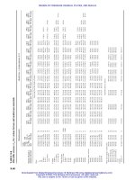
TABLE 18-42
Fluted and hexagon socket-headless setscrews
24
Fluted and hexagon socket types
Cone-point Hexagon type Fluted type
a
angle Y
Cup- and Socket Socket Socket Socket
Screw flat-point 118 Æ 28 90 Æ28 Dog point width diam, diam, land
size diameter Oval- for these for these across flats minor, major, width
nominal C point lengths lengths Diam P Key JJMN
diam radius and and engagement
†
D Max Min R under over Max Min Full Q Half q min Max Min Max Min Max Min Max Min
No. 0 0.033 0.027
3
64
1
16
5
64
0.040 0.037 0.030 0.015 0.022 0.0285 0.028 0.026 0.0255 0.035 0.034 0.012 0.0115
No. 1 0.040 0.033 0.055
5
64
3
32
0.049 0.045 0.037 0.019 0.028 0.0355 0.035 0.026 0.0255 0.035 0.034 0.012 0.0115
No. 2 0.047 0.039
1
16
3
32
7
64
0.057 0.053 0.043 0.022 0.028 0.0355 0.035 0.038 0.0375 0.050 0.049 0.017 0.016
No. 3 0.054 0.045
5
64
7
64
1
8
0.066 0.062 0.050 0.025 0.040 0.051 0.050 0.038 0.0375 0.050 0.049 0.017 0.016
No. 4 0.061 0.051 0.084
1
8
5
32
0.075 0.070 0.056 0.028 0.040 0.051 0.050 0.051 0.050 0.062 0.061 0.014 0.013
No. 5 0.067 0.057
3
32
1
8
3
16
0.083 0.078 0.06 0.03 0.050 0.0635
1
16
0.053 0.052 0.071 0.070 0.022 0.021
No. 6 0.074 0.064
7
64
1
8
3
16
0.092 0.087 0.07 0.035 0.050 0.0635
1
16
0.056 0.055 0.079 0.078 0.023 0.022
No. 8 0.087 0.076
1
8
3
16
1
4
0.109 0.103 0.08 0.04 0.062 0.0791
5
64
0.082 0.080 0.098 0.097 0.022 0.021
No. 10 0.102 0.088
9
64
3
16
1
4
0.127 0.120 0.09 0.045 0.075 0.0947
3
32
0.098 0.096 0.115 0.113 0.025 0.023
No. 12 0.115 0.101
5
32
3
16
1
4
0.144 0.137 0.11 0.055 0.075 0.0947
3
32
0.098 0.096 0.115 0.113 0.025 0.023
18.61
Downloaded from Digital Engineering Library @ McGraw-Hill (www.digitalengineeringlibrary.com)
Copyright © 2004 The McGraw-Hill Companies. All rights reserved.
Any use is subject to the Terms of Use as given at the website.
THREADED FASTENERS AND SCREWS FOR POWER TRANSMISSION
TABLE 18-42
Fluted and hexagon socket-headless setscrews
24
(Cont.)
Fluted and hexagon socket types
Cone-point Hexagon type Fluted type
a
angle Y
Cup- and Socket Socket Socket Socket
Screw flat-point 118 Æ 28 90 Æ28 Dog point width diam, diam, land
size diameter Oval- for these for these across flats minor, major, width
nominal C point lengths lengths Diam P Key JJMN
diam radius and and engagement
b
D Max Min R under over Max Min Full Q Half q min Max Min Max Min Max Min Max Min
1
4
0.132 0.118
3
16
1
4
5
16
5
32
0.149
1
8
1
16
0.100 0.1270
1
8
0.128 0.126 0.149 0.147 0.032 0.030
5
16
0.172 0.156
15
64
5
16
3
8
13
64
0.195
3
32
5
64
0.125 0.1582
5
32
0.163 0.161 0.188 0.186 0.039 0.037
3
8
0.212 0.194
9
32
3
8
7
16
1
4
0.241
3
16
3
32
0.150 0.1895
3
16
0.190 0.188 0.221 0.219 0.050 0.048
7
16
0.252 0.232
21
64
7
16
1
2
19
64
0.287
7
32
7
64
0.175 0.2207
7
32
0.221 0.219 0.256 0.254 0.060 0.058
1
2
0.291 0.270
3
8
1
2
9
16
11
32
0.334
1
4
1
8
0.200 0.2520
1
4
0.254 0.252 0.298 0.296 0.068 0.066
9
16
0.332 0.309
27
64
9
16
5
8
25
64
0.379
9
32
5
64
0.200 0.2520
1
4
0.254 0.252 0.298 0.296 0.068 0.066
5
8
0.371 0.347
15
32
5
8
3
4
15
32
0.456
5
16
3
32
0.250 0.3155
5
16
0.319 0.316 0.380 0.377 0.092 0.089
3
4
0.450 0.425
9
16
3
4
7
8
9
16
0.549
3
8
3
16
0.300 0.3780
3
8
0.386 0.383 0.463 0.460 0.112 0.109
7
8
0.530 0.502
21
32
7
8
1
21
32
0.642
7
16
7
32
0.400 0.5030
1
2
0.509 0.506 0.604 0.601 0.138 0.134
1 0.609 0.579
3
4
11
1
8
3
4
0.734
1
2
1
4
0.450 0.5655
9
16
0.535 0.531 0.631 0.627 0.149 0.145
1
1
8
0.689 0.655
27
32
1
1
8
1
1
4
27
32
0.826
9
16
9
16
0.450 0.5655
9
16
0.604 0.600 0.709 0.705 0.168 0.164
1
1
4
0.767 0.733
15
16
1
1
4
1
1
2
15
16
0.920
5
8
5
16
0.500 0.6290
3
8
0.685 0.681 0.801 0.797 0.189 0.185
1
3
8
0.848 0.808 1
1
32
1
3
8
1
5
8
1
1
32
1.011
11
16
11
32
0.500 0.6290
3
8
0.744 0.740 0.869 0.865 0.207 0.203
1
1
2
0.926 0.886 1
1
8
1
1
2
1
3
4
1
1
8
1.105
3
4
3
8
0.600 0.7540
3
4
0.828 0.824 0.970 0.966 0.231 0.227
1
3
4
1.086 1.039 1
5
16
1
3
4
21
5
16
1.289
7
8
7
16
0.800 0.0040 1 1.007 1.003 1.275 1.271 0.298 0.294
2 1.244 1.193 1
1
2
22
1
4
1
1
2
1.474 1
1
2
0.800 1.0040 1 1.007 1.003 1.275 1.271 0.298 0.294
a
The number of flutes for setscrews Nos. 0, 1, 2, 3, 5, and 6 is four. The number of flutes for Nos. 4, 8, and larger is six.
b
These dimensions apply to cup- and flat-point screws one diameter in length or longer. For screws shorter than one diameter in length, and for other types of points, socket to be as deep as
practicable.
Note: All dimensions are given in inches.
Source: Courtesy: John J. Viegas, Standards for Mechanical Elements, Harold A. Rothbart, Editor-in-Chief; Mechanical Design and Systems Handbook, McGraw-Hill Publishing Company, New
York, 1964.
18.62
Downloaded from Digital Engineering Library @ McGraw-Hill (www.digitalengineeringlibrary.com)
Copyright © 2004 The McGraw-Hill Companies. All rights reserved.
Any use is subject to the Terms of Use as given at the website.
THREADED FASTENERS AND SCREWS FOR POWER TRANSMISSION
TABLE 18-43
American National Standard metric hex cap screws (ANSI B18.2.3.1M-1979, R1989)
Width across Width across Head Wrenching Washer
Nominal Body diam, flats, corners, height, height, face thickness,
screw D
s
SEKK
1
C
diam, D and
thread pitch Max Min Max Min Max Min Max Min Min Max Min
M5 Â 0:8 5.00 4.82 8.00 7.78 9.24 8.79 3.65 3.35 2.4 0.5 0.2
M6 Â 1 6.00 5.82 10.00 9.78 11.55 11.05 4.15 3.85 2.8 0.5 0.2
M8 Â 1:25 8.00 7.78 13.00 12.73 15.01 14.38 5.50 5.10 3.7 0.6 0.3
M10 Â 1:5
Ã
10.00 9.78 15.00 14.73 17.32 16.64 6.63 6.17 4.5 0.6 0.3
M10 Â 1:5 10.00 9.78 16.00 15.73 18.48 17.77 6.63 6.17 4.5 0.6 0.3
M12 Â 1:75 12.00 11.73 18.00 17.73 20.78 20.03 7.76 7.24 5.2 0.6 0.3
M14 Â 2 14.00 13.73 21.00 20.67 24.25 23.35 9.09 8.51 6.2 0.6 0.3
M16 Â 2 16.00 15.73 24.00 23.67 27.71 26.75 10.32 8.68 7.0 0.8 0.4
M20 Â 2:5 20.00 19.67 30.00 29.16 34.64 32.95 12.88 12.12 8.8 0.8 0.4
M24 Â 3 24.00 23.67 36.00 35.00 41.57 39.55 15.44 14.56 10.5 0.8 0.4
M30 Â 3:5 30.00 29.67 46.00 45.00 53.12 50.85 15.48 17.92 13.1 0.8 0.4
M36 Â 4 36.00 35.61 55.00 53.80 63.51 60.79 23.38 21.62 15.8 0.8 0.4
M42 Â 4:5 42.00 41.38 65.00 62.90 75.06 71.71 26.97 25.03 18.2 1.0 0.5
M48 Â 5 48.00 47.38 75.00 72.60 86.60 83.76 31.07 28.93 21.0 1.0 0.5
M56 Â 5:5 56.00 55.26 85.00 82.20 98.15 93.71 36.20 33.80 24.5 1.0 0.5
M64 Â 6 64.00 63.26 95.00 91.80 109.70 104.65 41.32 38.68 28.0 1.0 0.5
M72 Â 6 72.00 71.26 105.00 101.40 121.24 115.60 46.45 43.55 31.5 1.2 0.6
M80 Â 6 80.00 79.26 115.00 111.00 132.72 126.54 51.58 48.42 35.0 1.2 0.6
M90 Â 6 90.00 89.13 130.00 125.50 150.11 143.07 57.74 54.26 39.2 1.2 0.6
M100 Â 6 100.00 99.13 145.00 140.00 167.43 159.60 63.90 60.10 43.4 1.2 0.6
All dimensions are in millimeters.
Ã
This size with width across flats of 15 mm is not standard. Unless specifically ordered hex cap screws with 16 mm width across flats will be
furnished.
†
Transition thread length, X, includes the length of incomplete threads and tolerances gaging length and body length. It is intended for calculation
purposes.
‡
Basic thread lengths, B, are the same as given in Table 18-47.
For additional manufacturing and acceptance specifications, reference should be made to Standard.
Courtesy: American National Standards Institution, New York, USA. (ANSI B18.2.1M-1979, R1989)
THREADED FASTENERS AND SCREWS FOR POWER TRANSMISSION 18.63
Downloaded from Digital Engineering Library @ McGraw-Hill (www.digitalengineeringlibrary.com)
Copyright © 2004 The McGraw-Hill Companies. All rights reserved.
Any use is subject to the Terms of Use as given at the website.
THREADED FASTENERS AND SCREWS FOR POWER TRANSMISSION
TABLE 18-44
American National Standard metric formed hex screws (ANSI B18.2.3.2M-1979, R1989)
Nominal Width across Width across Head Wrenching Washer Washer
screw Body diam, flats, corners, height, height, face thickness, face diam,
diam, D, D
s
SEKK
1
CD
w
and thread
pitch Max Min Max Min Max Min Max Min Min Max Min Min
M5 Â 0:8 5.00 4.82 8.00 7.64 9.24 8.56 3.65 3.35 2.4 0.5 0.2 6.9
M6 Â 1 5.00 5.82 10.00 9.64 11.55 10.80 4.15 3.85 2.0 0.5 0.2 8.9
M8 Â 1:25 8.00 7.78 13.00 12.57 15.01 14.08 5.50 5.10 3.7 0.6 0.3 11.6
M10 Â 1:5
Ã
10.00 9.78 15.00 14.57 17.32 16.32 6.63 6.17 4.5 0.6 0.3 13.6
M10 Â 1:5 10.00 9.78 16.00 15.57 18.48 17.43 6.63 6.17 4.5 0.6 0.3 14.6
M12 Â 1:75 12.00 11.73 18.00 17.57 20.78 19.68 7.76 7.24 5.2 0.6 0.3 16.6
M14 Â 2 14.00 13.73 21.00 20.16 24.25 22.58 9.09 8.51 6.2 0.6 0.3 19.6
M16 Â 2 16.00 15.73 24.00 23.16 27.71 25.94 10.32 9.68 7.0 0.8 0.4 22.5
M20 Â 2:5 20.00 19.67 30.00 29.16 34.64 32.66 12.88 12.12 8.8 0.8 0.4 27.7
M24 Â 3 24.00 23.67 36.00 35.00 41.57 39.20 15.44 14.56 10.5 0.8 0.4 32.2
All dimensions are in millimeters.
Ã
This size with width across flats of 15 mm is not standard. Unless specifically ordered M10 formed hex screws with 16 mm width across flats will be
furnished.
†
Transition thread length, X, includes the length of incomplete threads and tolerances on the grip gaging length and body length. It is intended for
calculation purposes.
‡
Basic thread lengths, B are the same as given in Table 18-47.
For additional manufacturing and acceptance specifications, reference should be made to the Standard.
Courtesy: American National Standards Institution, New York, USA. (ANSI B18.2.3.2M-1979, R1989)
18.64 CHAPTER EIGHTEEN
Downloaded from Digital Engineering Library @ McGraw-Hill (www.digitalengineeringlibrary.com)
Copyright © 2004 The McGraw-Hill Companies. All rights reserved.
Any use is subject to the Terms of Use as given at the website.
THREADED FASTENERS AND SCREWS FOR POWER TRANSMISSION
TABLE 18-45
American National Standard metric heavy hex screws (ANSI B18.2.3.3M-1979, R1989)
Nominal Width across Width across Head Wrenching Washer Washer
screw Body diam, flats, corners, height, height, face thickness, face diam,
diam, D, D
s
SEKK
1
CD
w
and thread
pitch Max Min Max Min Max Min Max Min Min Max Min Min
M12 Â 1:75 12.00 11.73 21.00 20.67 24.25 23.35 7.76 7.24 5.2 0.6 0.3 19.0
M14 Â 2 14.00 13.73 24.00 23.67 27.71 26.75 9.09 8.51 6.2 0.6 0.3 22.0
M16 Â 2 16.00 15.73 27.00 26.67 31.18 30.14 10.32 9.68 7.0 0.8 0.4 25.0
M20 Â 2:5 20.00 19.67 34.00 33.00 39.26 37.29 12.88 12.12 8.8 0.8 0.4 31.0
M24 Â 3 24.00 23.67 41.00 40.00 47.34 45.20 15.44 14.56 10.5 0.8 0.4 38.0
M30 Â 3:5 30.00 29.67 50.00 49.00 57.74 55.37 19.48 17.92 13.1 0.8 0.4 46.0
M36 Â 4 36.00 35.61 60.00 58.80 69.28 66.44 23.38 21.72 15.8 0.8 0.4 55.0
All dimensions are in millimeters
Basic thread lengths, B, are the same as given in Table 18-47.
Transition thread length, X, includes the length of incomplete threads and tolerances on the grip gaging length and body length. It is intended for
calculation purposes.
For additional manufacturing and acceptance specifications, reference should be made to the Standard.
THREADED FASTENERS AND SCREWS FOR POWER TRANSMISSION 18.65
Downloaded from Digital Engineering Library @ McGraw-Hill (www.digitalengineeringlibrary.com)
Copyright © 2004 The McGraw-Hill Companies. All rights reserved.
Any use is subject to the Terms of Use as given at the website.
THREADED FASTENERS AND SCREWS FOR POWER TRANSMISSION
TABLE 18-46
American National Standard metric hex flange screws (ANSI/ASME B18.2.3.4M-1984)
Nominal
screw Width Width Bearing Flange
diam, Body across across Flange circle edge Head Wrenching Fillet
D, diam, flats, corners, diam, diam, thickness height, height, radius,
and D
s
SED
c
D
w
CK K
1
R
thread
pitch Max Min Max Min Max Min Max Min Min Max Min Max
M5 Â 0:8 5.00 4.82 7.00 6.64 8.08 7.44 11.4 9.4 1.0 5.6 2.30 0.3
M6 Â 1 6.00 5.82 8.00 7.64 9.24 8.56 13.6 11.6 1.1 6.8 2.90 0.4
M8 Â 1:25 8.00 7.78 10.00 9.64 11.55 10.80 17.0 14.9 1.2 8.5 3.80 0.5
M10 Â 1:5 10.00 9.78 13.00 12.57 15.01 14.08 20.8 18.7 1.5 9.7 4.30 0.6
M12 Â 1:75 12.00 11.73 15.00 14.57 17.32 16.32 24.7 22.0 1.8 11.9 5.40 0.7
M14 Â 2 14.00 13.73 18.00 17.57 20.78 19.68 28.6 25.9 2.1 12.9 5.60 0.8
M16 Â 2 16.00 15.73 21.00 20.48 24.25 22.94 32.8 30.1 2.4 15.1 6.70 1.0
All dimensions are in millimeters.
Basic thread lengths, B, are the same as given in Table 18-47.
Transition thread length, X, includes the length of incomplete threads and tolerances on grip gaging length and body length.
This dimension is intended for calculation purposes only.
For additional manufacturing and acceptance specifications, reference should be made to the Standard.
18.66 CHAPTER EIGHTEEN
Downloaded from Digital Engineering Library @ McGraw-Hill (www.digitalengineeringlibrary.com)
Copyright © 2004 The McGraw-Hill Companies. All rights reserved.
Any use is subject to the Terms of Use as given at the website.
THREADED FASTENERS AND SCREWS FOR POWER TRANSMISSION
TABLE 18-47
Received diameter-length combinations for metric hex cap screws, formed hex screws, heavy hex screws, hex flange
screws and heavy hex flange screws
Diameter—Pitch
Nominal M5 M6 M8 M10 M12 M14 M16 M20 M24 M30 M36
Length
a
Â0.8 Â1 Â1.25 Â1.5 Â1.75 Â2 Â2 Â2.5 Â3 Â3.5 Â4
8 Â ——————————
10 —————————
12 ————————
14 ÂÂÂÂ
b
———————
16 ÂÂÂÂ
b
Â
b
Â
b
—————
20 —————
25 ————
30 ———
35 ——
40 —
45 —
50 ÂÂÂÂÂÂÂÂÂÂÂ
(55) — ÂÂÂÂÂÂÂÂÂÂ
60 — ÂÂÂÂÂÂÂÂÂÂ
(65) — — ÂÂÂÂÂÂÂÂÂ
70 — — ÂÂÂÂÂÂÂÂÂ
(75) — — ÂÂÂÂÂÂÂÂÂ
80 — — ÂÂÂÂÂÂÂÂÂ
(85) — — — ÂÂÂÂÂÂÂÂ
90 — — — ÂÂÂÂÂÂÂÂ
100 — — — ÂÂÂÂÂÂÂÂ
110 — — — — ÂÂÂÂÂÂÂ
120 — — — — ÂÂÂÂÂÂÂ
130 —————ÂÂÂÂÂÂ
140 —————ÂÂÂÂÂÂ
150 ——————ÂÂÂÂÂ
160 ——————ÂÂÂÂÂ
(170) — ——————ÂÂÂÂ
180 ———————ÂÂÂÂ
(190) — ——————ÂÂÂÂ
200 ———————ÂÂÂÂ
220 ————————ÂÂÂ
240 ————————ÂÂÂ
260 —————————ÂÂ
280 —————————ÂÂ
300 —————————ÂÂ
All dimensions are in millimeters.
a
Lengths in parentheses are not recommended. Recommended lengths of formed Hex Screws, Hex Flange Screws and Heavy Hex Flange Screws
do not extend above 150 mm. Recommended lengths of Heavy Hex Screws do not extend below 20 mm. Standard sizes for government use.
Recommended diameter-length combinations are indicated by the symbol Â. Screws with lengths above cross lines are threaded full length.
b
Does not apply to Hex Flange Screws and Heavy Hex Flange Screws.
For available diameters of each type of screw, see respective dimensional table.
THREADED FASTENERS AND SCREWS FOR POWER TRANSMISSION 18.67
Downloaded from Digital Engineering Library @ McGraw-Hill (www.digitalengineeringlibrary.com)
Copyright © 2004 The McGraw-Hill Companies. All rights reserved.
Any use is subject to the Terms of Use as given at the website.
THREADED FASTENERS AND SCREWS FOR POWER TRANSMISSION
TABLE 18-48
American National Standard Metric Hex Bolts (ANSI B18.2.3.5M-1979, R1989)
Nominal For bolt lengths (mm)
bolt Width Widths
diam, Body across across Head Wrenching >125
D, diam, flats, corners, height, height, and
and D
s
SEKK
1
<125 <200 >200
thread
pitch Max Min Max Min Max Min Max Min Min Basic thread length,
b
B
M5 Â 0:8 5.48 4.52 8.00 7.64 9.24 8.63 3.58 3.35 2.4 16 22 35
M6 Â 1 6.19 5.52 10.00 9.64 11.55 10.89 4.18 3.55 2.8 18 24 37
M8 Â 1:25 8.58 7.42 13.00 12.57 15.01 14.20 5.68 5.10 3.7 22 28 41
a
M10 Â 1:5 10.58 9.42 15.00 14.57 17.32 16.46 6.85 6.17 4.5 26 32 45
M10 Â 1:5 10.58 9.42 16.00 15.57 18.48 17.59 6.85 6.17 4.5 26 32 45
M12 Â 1:75 12.70 11.30 18.00 17.57 20.78 19.85 7.95 7.24 5.2 30 36 49
M14 Â 2 14.70 13.30 21.00 20.16 24.25 22.78 9.25 8.51 6.2 34 49 53
M16 Â 2 16.70 15.30 24.00 23.16 27.71 26.17 10.75 9.68 7.0 38 44 57
M20 Â 2:5 20.84 19.16 30.00 29.16 34.64 32.95 13.40 12.12 8.8 46 52 65
M24 Â 3 24.84 23.16 36.00 35.00 41.57 39.55 15.90 14.56 10.5 54 60 73
M30 Â 3:5 30.84 29.16 46.00 45.00 53.12 50.55 19.75 17.92 13.1 66 72 85
M36 Â 4 37.00 35.00 55.00 53.80 63.51 60.79 23.55 21.72 15.8 78 84 97
M42 Â 4:5 43.00 41.00 65.00 62.90 75.06 71.71 27.05 25.03 18.2 90 96 109
M48 Â 5 49.00 47.00 75.00 72.60 86.60 82.76 31.07 28.93 21.0 102 108 121
M56 Â 5:5 57.20 54.80 85.00 82.20 98.15 93.71 36.20 33.80 24.5 — 124 137
M64 Â 6 65.52 63.80 95.00 91.80 109.70 104.65 41.32 38.68 28.0 — 140 153
M72 Â 6 73.84 70.80 105.00 101.40 121.24 115.60 46.45 43.55 31.5 — 156 169
M80 Â 6 82.16 78.80 115.00 111.00 132.79 126.54 51.58 48.42 35.0 — 172 185
M90 Â 6 92.48 88.60 130.00 125.50 150.11 143.07 57.74 54.26 39.2 — 192 205
M100 Â 6 102.80 98.60 145.00 140.00 167.43 159.60 63.90 60.10 43.4 — 212 225
All dimensions are in millimeters.
a
This size with width across flats of 15 mm is not standard. Unless specifically ordered, M10 set bolts with 16 mmm width across flats will be
furnished.
b
Basic thread length, B, is a reference dimension.
For additional manufacturing and acceptance specifications, reference should be made to the Standard.
18.68 CHAPTER EIGHTEEN
Downloaded from Digital Engineering Library @ McGraw-Hill (www.digitalengineeringlibrary.com)
Copyright © 2004 The McGraw-Hill Companies. All rights reserved.
Any use is subject to the Terms of Use as given at the website.
THREADED FASTENERS AND SCREWS FOR POWER TRANSMISSION
TABLE 18-49
American National Standard Heavy Hex Bolts (ANSI B18.2.3.6M-1979, R1989)
Nominal Body diam, Width across flats, Width across corners, Head height, Wrenching
diam, DD
s
SEKheight, K
1
and thread
pitch Max Min Max Min Max Min Max Min Min
M12 Â 1:75 12.70 11.30 21.00 29.16 24.25 22.78 7.95 7.24 5.2
M14 Â 2 14.70 13.30 24.00 23.16 27.71 26.17 9.25 8.51 6.2
M16 Â 2 16.70 15.30 27.00 26.16 31.18 29.56 10.75 9.68 7.2
M20 Â 2:5 20.84 19.16 34.00 33.00 39.26 37.29 13.40 12.12 8.2
M24 Â 3 24.84 23.16 41.00 40.00 47.34 45.20 15.90 14.56 10.5
M30 Â 3:5 30.84 29.16 50.00 49.00 57.74 55.37 19.75 17.92 13.1
M36 Â 4 37.00 35.00 60.00 58.80 69.28 66.44 23.55 21.72 15.1
All dimensions are in millimeters.
a
Basic thread lengths, B, are the same as given in Table 18-47.
For additional manufacturing and acceptance specifications, reference should be made to the Standard.
THREADED FASTENERS AND SCREWS FOR POWER TRANSMISSION 18.69
Downloaded from Digital Engineering Library @ McGraw-Hill (www.digitalengineeringlibrary.com)
Copyright © 2004 The McGraw-Hill Companies. All rights reserved.
Any use is subject to the Terms of Use as given at the website.
THREADED FASTENERS AND SCREWS FOR POWER TRANSMISSION
TABLE 18-50
Recommended clearance holes for metric hex screws and bolts
a
Nominal Clearance hole diam, basic, D
h
Nominal Clearance hole diam, basic, D
h
diam, D and diam, D and
thread pitch Close Normal, preferred Loose thread pitch Close Normal, preferred Loose
M5 Â 0:8 5.3 5.5 5.8 M30 Â3:5 31.0 33.0 35.0
M6 Â 1 6.4 6.6 7.0 M36 Â 4 37.0 39.0 42.0
M8 Â 1:25 8.4 9.0 10.0 M42 Â 4:5 43.0 45.0 48.0
M10 Â 1:5 10.5 11.0 12.0 M48 Â 5 50.0 52.0 56.0
M12 Â 1:75 13.0 13.5 14.5 M56 Â5:5 58.0 62.0 66.0
M14 Â 2 15.0 15.5 16.5 M64 Â 6 66.0 70.0 74.0
M16 Â 2 17.0 17.5 18.5 M72 Â 6 74.0 78.0 82.0
M20 Â 2:5 21.0 22.0 24.0 M80 Â 6 82.0 86.0 91.0
M22 Â 2:5
b
23.0 24.0 26.0 M90 Â6 93.0 96.0 101.0
M24 Â 3 25.0 26.0 28.0 M100 Â 6 104.0 107.0 112.0
M27 Â 3
b
28.0 30.0 32.0 — — — —
All dimensions are in millimeters.
a
Does not apply to hex lag screws, hex socket headless screws, or round head square neck bolts.
b
Applies only to heavy hex structural bolts.
Normal Clearance: This is preferred for general purpose applications and should be specified unless special design considerations dictate the need
for either a close or loose clearance hole.
Close Clearance: This should be specified only where conditions such as critical alignment of assembled parts, wa ll thickness or other limitations
necessitate use of a minimum hole. When close clearance holes are specified, special provision (e.g. countersinking) must be made at the screw used
bolt entry side to permit proper seating of the screw or bolt head.
Loose Clearance: This should be specified only for applications where maximum adjustment capability between components being assembled is
necessary.
Recommended Tolerances: The clearance hole diameters given in this table are minimum. Recommended tolerances are: for screw or bolt diameter
M5, þ0:2 mm; for M6 through M8, þ0:3 mm; for M20 through M24, þ0:4 mm; for M48 through M72, þ0:5 mm; and for M80 through M100,
þ0:6 mm.
18.70 CHAPTER EIGHTEEN
Downloaded from Digital Engineering Library @ McGraw-Hill (www.digitalengineeringlibrary.com)
Copyright © 2004 The McGraw-Hill Companies. All rights reserved.
Any use is subject to the Terms of Use as given at the website.
THREADED FASTENERS AND SCREWS FOR POWER TRANSMISSION
TABLE 18-51
American National Standard metric hex screws and bolts—reduced body diameters
Nominal Shoulder Body Shoulder Nominal Shoulder Body Shoulder
diam, D, diam,
b
diam, length,
b
diam, D, diam,
b
diam, length,
b
and D
s
D
si
L
sh
and D
s
D
si
L
sh
thread thread
pitch Max Min Max Min Max Min pitch Max Min Max Min Max Min
Metric Formed Hex Screws (ANSI B18.2.3.2M-1979, R1989)
M5 Â 0:8 5.00 4.82 4.46 4.36 3.5 2.5 M14 Â2 14.00 13.73 12.77 12.50 8.0 7.0
M6 Â 1 6.00 5.82 5.39 5.21 4.0 3.0 M16 Â2 16.00 15.73 14.77 14.50 9.0 8.0
M8 Â 1:25 8.00 7.78 7.26 5.04 5.0 4.0 M20 Â2:5 20.00 19.67 18.49 18.16 11.0 10.0
M10 Â 1:5 10.00 9.78 9.08 8.86 6.0 5.0 M24 Â3 24.00 23.67 22.13 21.80 13.0 12.0
M12 Â 1:7512.0011.7310.9510.687.06.0— ——————
Metric Hex Flange Screws (ANSI B18.2.3.4M-1984)
M5 Â 0:8 5.00 4.82 4.46 4.36 3.5 2.5 M12 Â1:75 12.00 11.73 10.95 10.68 7.0 6.0
M6 Â 1 6.00 5.82 5.39 5.21 4.0 3.0 M14 Â2 14.00 13.73 12.77 12.50 8.0 7.0
M8 Â 1:25 8.00 7.78 7.26 7.04 5.0 4.0 M16 Â2 16.00 15.73 14.77 14.50 9.0 8.0
M10 Â 1:510.009.789.088.866.05.0— ——————
Metric Hex Bolts (ANSI B18.2.3.5M-1979, R1989)
M5 Â 0:8 5.48 4.52 4.46 4.36 3.5 2.5 M14 Â2 14.70 13.30 12.77 12.50 8.0 7.0
M6 Â 1 6.48 5.52 5.39 5.21 4.0 3.0 M16 Â2 16.70 15.30 14.77 14.50 9.0 8.0
M8 Â 1:25 8.58 7.42 7.26 7.04 5.0 4.0 M20 Â2:5 20.84 19.16 18.49 18.16 11.0 10.0
M10 Â 1:5 10.58 9.42 9.08 8.86 6.0 5.0 M24 Â3 24.84 23.16 22.13 21.80 13.0 12.0
M12 Â 1:7512.7011.3010.9510.687.06.0— ——————
Metric Heavy Hex Bolts (ANSI B18.2.3.6M-1979, R1989)
M12 Â 1:75 12.70 11.30 10.95 10.68 7.0 6.0 M20 Â 2:5 20.84 19.16 18.49 18.16 11.0 10.0
M14 Â 2 14.70 13.30 12.77 12.50 8.0 7.0 M24 Â 3 24.84 23.16 22.13 21.80 13.0 12.0
M16 Â 216.7015.3014.7714.509.08.0— ——————
Metric Heavy Hex Flange Screws (ANSI B18.2.3.9M- 1984)
M10 Â 1:5 10.00 9.78 9.08 8.86 6.0 5.0 M16 Â2 16.00 15.73 14.77 14.50 9.0 8.0
M12 Â 1:75 12.00 11.73 10.95 10.68 7.0 6.0 M20 Â 2:5 20.00 19.67 18.49 18.16 11.0 10.0
M14 Â 214.0013.7312.7712.508.07.0— ——————
All dimensions are in millimeters.
a
Shoulder is mandatory for formed hex screws, hex flange screws, and heavy hex flange screws. Shoulder is optional for hex bolts and heavy hex
bolts.
THREADED FASTENERS AND SCREWS FOR POWER TRANSMISSION 18.71
Downloaded from Digital Engineering Library @ McGraw-Hill (www.digitalengineeringlibrary.com)
Copyright © 2004 The McGraw-Hill Companies. All rights reserved.
Any use is subject to the Terms of Use as given at the website.
THREADED FASTENERS AND SCREWS FOR POWER TRANSMISSION
TABLE 18-52
American National Standard metric heavy hex structural bolts (ANSI B18.2.3.7M-1979, R1989)
Thread length, B
a
Transi-
Width Width Washer Washer tion
Nominal Body across across Head Wrenching face face Bolt Bolt thread
bolt diam, flats, corners, height, height, diam, thickness, lengths, lengths, length,
diam, D, D
S
SEKK
1
D
w
C 100 >100 X
b
thread
pitch Max Min Max Min Max Min Max Min Min Min Max Min Basic Max
M16 Â 2 16.70 15.30 27.00 26.16 31.18 29.56 10.75 9.26 6.5 24.9 0.8 0.4 31 38 6.0
M20 Â 2:5 20.84 19.16 34.00 33.00 39.26 37.29 13.40 11.60 8.1 31.4 0.8 0.4 36 43 7.5
M22 Â 2:5 22.84 21.16 36.00 35.00 41.57 39.55 14.90 13.10 9.2 33.3 0.8 0.4 38 45 7.5
M24 Â 3 24.84 23.16 41.00 40.00 47.34 45.20 15.90 14.10 9.9 38.0 0.8 0.4 41 48 9.0
M27 Â 3 27.84 26.16 46.00 45.00 53.12 50.85 17.90 16.10 11.3 42.8 0.8 0.4 44 51 9.0
M30 Â 3:5 30.84 29.16 50.00 49.00 57.74 55.37 19.75 17.65 12.4 46.5 0.8 0.4 49 56 10.5
M36 Â 4 37.00 35.00 60.00 58.80 69.28 66.44 23.55 21.45 15.0 55.9 0.8 0.4 56 63 12.0
18.72 CHAPTER EIGHTEEN
Downloaded from Digital Engineering Library @ McGraw-Hill (www.digitalengineeringlibrary.com)
Copyright © 2004 The McGraw-Hill Companies. All rights reserved.
Any use is subject to the Terms of Use as given at the website.
THREADED FASTENERS AND SCREWS FOR POWER TRANSMISSION
TABLE 18-53
Recommended diameter-length combinations for metric heavy hex structural bolts
Nominal Nominal diameter and thread pitch
length,
L M16 Â2 M20 Â 2:5 M22 Â 2:5M24Â 3 M27 Â3 M30 Â3:5 M36 Â 4
45 Â ——————
50 —————
55 ————
60 ———
65 ——
70 —
75 —
80 ÂÂÂÂÂÂÂ
85 ÂÂÂÂÂÂÂ
90 ÂÂÂÂÂÂÂ
95 ÂÂÂÂÂÂÂ
100 ÂÂÂÂÂÂÂ
110 ÂÂÂÂÂÂÂ
120 ÂÂÂÂÂÂÂ
130 ÂÂÂÂÂÂÂ
140 ÂÂÂÂÂÂÂ
150 ÂÂÂÂÂÂÂ
160 ÂÂÂÂÂÂÂ
170 ÂÂÂÂÂÂÂ
180 ÂÂÂÂÂÂÂ
190 ÂÂÂÂÂÂÂ
200 ÂÂÂÂÂÂÂ
210 ÂÂÂÂÂÂÂ
220 ÂÂÂÂÂÂÂ
230 ÂÂÂÂÂÂÂ
240 ÂÂÂÂÂÂÂ
250 ÂÂÂÂÂÂÂ
260 ÂÂÂÂÂÂÂ
270 ÂÂÂÂÂÂÂ
280 ÂÂÂÂÂÂÂ
290 ÂÂÂÂÂÂÂ
300 ÂÂÂÂÂÂÂ
All dimensions are in millimeters.
Recommended diameter-length combinations are indicated by the symbol Â.
Bolts with lengths above the heavy cross lines are threaded full length.
THREADED FASTENERS AND SCREWS FOR POWER TRANSMISSION 18.73
Downloaded from Digital Engineering Library @ McGraw-Hill (www.digitalengineeringlibrary.com)
Copyright © 2004 The McGraw-Hill Companies. All rights reserved.
Any use is subject to the Terms of Use as given at the website.
THREADED FASTENERS AND SCREWS FOR POWER TRANSMISSION
TABLE 18-54
American National Standard metric hex nuts, Styles 1 and 2 (ANSI B18.2.4.1M and B18.2.4.2M-1979, R1989)
Width across Width across Bearing Washer face
Nominal flats, corners, Thickness, face diam, thickness
nut diam, SEMD
w
C
and thread
pitch Max Min Max Min Max Min Min Max Min
Metric Hex Nuts—Style 1
M1:6 Â 0:35 3.20 3.02 3.70 3.41 1.30 1.05 2.3 — —
M2 Â 0:4 4.00 3.82 4.62 4.32 1.60 1.35 3.1 — —
M2:5 Â 0:45 5.00 4.82 5.77 5.45 2.00 1.75 4.1 — —
M3 Â 0:5 5.50 5.32 6.35 6.01 2.40 2.15 4.6 — —
M3:5 Â 0:6 6.00 5.82 6.93 6.58 2.80 2.55 5.1 — —
M4 Â 0:7 7.00 6.78 8.08 7.66 3.20 2.90 6.0 — —
M5 Â 0:8 8.00 7.78 9.24 8.79 4.70 4.40 7.0 — —
M6 Â 1 10.00 9.78 11.55 11.05 5.20 4.90 8.9 — —
M8 Â 1:25 13.00 12.73 15.01 14.38 6.80 6.44 11.6 — —
a
M10 Â 1:5 15.00 14.73 17.32 16.64 9.1 8.7 13.6 0.6 0.3
M10 Â 1:5 16.00 15.73 18.48 17.77 8.40 8.04 14.6 — —
M12 Â 1:75 18.00 17.73 20.78 20.03 10.80 10.37 16.6 — —
M14 Â 2 21.00 20.67 24.25 23.36 12.80 12.10 19.4 — —
M16 Â 2 24.00 23.67 27.71 26.75 14.80 14.10 22.4 — —
M20 Â 2:5 30.00 29.16 34.64 32.95 18.00 16.90 27.9 0.8 0.4
M24 Â 3 36.00 35.00 41.57 39.55 21.50 20.20 32.5 0.8 0.4
M30 Â 3:5 46.00 45.00 53.12 50.85 25.60 24.30 42.5 0.8 0.4
M36 Â 4 55.00 53.80 63.51 60.79 31.00 29.40 50.8 0.8 0.4
Metric Hex Nuts—Style 2
M3 Â 0:5 5.50 5.32 6.35 6.01 2.90 2.65 4.6 — —
M3:5 Â 0:6 6.00 5.82 6.93 6.58 3.30 3.00 5.1 — —
M4 Â 0:7 7.00 6.78 8.08 7.66 3.80 3.50 5.9 — —
M5 Â 0:8 8.00 7.78 9.24 8.79 5.10 4.80 6.9 — —
M6 Â 1 10.00 9.78 11.55 11.05 5.70 5.40 8.9 — —
M8 Â 1:25 13.00 12.73 15.01 14.38 7.50 7.14 11.6 — —
a
M10 Â 1:5 15.00 14.73 17.32 16.64 10.0 9.6 13.6 0.6 0.3
M10 Â 1:5 16.00 15.73 18.48 17.77 9.30 8.94 14.6 — —
M12 Â 1:75 18.00 17.73 20.78 20.03 12.00 11.57 16.6 — —
M14 Â 2 21.00 20.67 24.25 23.35 14.10 13.40 19.6 — —
M16 Â 2 24.00 23.67 27.71 26.75 16.40 15.70 22.5 — —
M20 Â 2:5 30.00 29.16 34.64 32.95 20.30 19.00 27.7 0.8 0.4
M24 Â 3 36.00 35.00 41.57 39.55 23.90 22.60 33.3 0.8 0.4
M30 Â 3:5 46.00 45.00 53.12 50.85 28.60 27.30 42.7 0.8 0.4
M36 Â 4 55.00 53.80 63.51 60.79 34.70 33.10 51.1 0.8 0.4
All dimensions are in millimeters.
a
This size with width across flats of 15 mm is not standard. Unless specifically ordered, metric hex nuts with 16 mm width across flats will be furnished.
18.74
Downloaded from Digital Engineering Library @ McGraw-Hill (www.digitalengineeringlibrary.com)
Copyright © 2004 The McGraw-Hill Companies. All rights reserved.
Any use is subject to the Terms of Use as given at the website.
THREADED FASTENERS AND SCREWS FOR POWER TRANSMISSION
TABLE 18-55
American National Standard metric slotted hex nuts (ANSI B18.2.4.3M-1979, R1989)
Width across Width across Bearing Unslotted Width Washer
Nominal nut flats, corners, Thickness, face diam, thickness, of slot, face thickness,
diam, D, SEMD
w
FNC
and thread
pitch Max Min Max Min Max Min Min Max Min Max Min Max Min
M5 Â 0:8 8.00 7.78 9.24 8.79 5.10 4.80 6.9 3.2 2.9 2.0 1.4 — —
M6 Â 1 10.00 9.78 11.55 11.05 5.70 5.40 8.9 3.5 3.2 2.4 1.8 — —
M8 Â 1:25 13.00 12.73 15.01 14.38 7.50 7.14 11.6 4.4 4.1 2.9 2.3 — —
a
M10 Â 1:5 15.00 14.73 17.32 16.64 10.0 9.6 13.6 5.7 5.4 3.4 2.8 0.6 0.3
M10 Â 1:5 16.00 15.73 18.48 17.77 9.30 8.94 14.6 5.2 4.9 3.4 2.8 — —
M12 Â 1:75 18.00 17.73 20.78 20.03 12.00 11.57 16.6 7.3 6.9 4.0 3.2 — —
M14 Â 2 21.00 20.67 24.25 23.35 14.10 13.40 19.6 8.6 8.0 4.3 3.5 — —
M16 Â 2 24.00 23.67 27.71 26.75 16.40 15.70 22.5 9.9 9.3 5.3 4.5 — —
M20 Â 2:5 30.00 29.16 34.64 32.95 20.30 19.00 27.7 13.3 12.2 5.7 4.5 0.8 0.4
M24 Â 3 36.00 35.00 41.57 39.55 23.90 22.60 33.2 15.4 14.3 6.7 5.5 0.8 0.4
M30 Â 3:5 46.00 45.00 53.12 50.85 28.60 27.30 42.7 18.1 16.8 8.5 7.0 0.8 0.4
M36 Â 4 55.00 53.80 63.51 60.79 34.70 33.10 51.1 23.7 22.4 8.5 7.0 0.8 0.4
All dimensions are in millimeters.
a
This size with width across flats of 15 mm is not standard. Unless specifically ordered, M10 slotted hex nuts with 16 mm width across flats will be
furnished.
THREADED FASTENERS AND SCREWS FOR POWER TRANSMISSION 18.75
Downloaded from Digital Engineering Library @ McGraw-Hill (www.digitalengineeringlibrary.com)
Copyright © 2004 The McGraw-Hill Companies. All rights reserved.
Any use is subject to the Terms of Use as given at the website.
THREADED FASTENERS AND SCREWS FOR POWER TRANSMISSION
REFERENCES
1. Norman, C. A., E. S. Ault, and E. F. Zarobsky, Fundamentals of Machine Design, The Macmillan Company,
New York, 1951.
2. Maleev, V. L., and J. B. Hartman, Machine Design, International Textbook Company, Scranton,
Pennsylvania, 1954.
3. Black, P. H., and O. E. Adams, Jr., Machine Design, McGraw-Hill Publishing Company, New York, 1955.
4. Baumeister, T., ed., Marks’ Standard Handbook for Mechanical Engineers, 8th ed., McGraw-Hill Publishing
Company, New York, 1978.
5. Lingaiah, K., and B. R. Narayana Iyengar, Machine Design Data Handbook, Engineering College Cooperative
Society, Bangalore, India, 1962.
6. Lingaiah, K., and B. R. Narayana Iyengar, Machine Design Data Handbook, Vol. I (SI and Customary Metric
Units), Suma Publishers, Bangalore, India, 1986.
7. Lingaiah, K., Machine Design Data Handbook, Vol. II (SI and Customary Metric Units), Suma Publishers,
Bangalore, India, 1986.
8. Bureau of Indian Standards.
9. ISO Standards.
10. John, J. Viegas, Standards for Mechanical Elements, Harold A. Rothbart, Editor-in-Chief, Mechanical Design
and Systems Handbook, McGraw-Hill Publishing Company, New York, 1964.
11. Russel, Bardsall and Ward Corp., Helpful Hints for Fastener Design and Application, Mentor, Ohio, 1976,
p. 42.
12. Shigley J., E., and C. R. Mischke, Mechanical Engineering Design, 5th ed., McGraw-Hill Publishing
Company, New York, 1989.
13. Burr, J. H., and J. B. Cheatham, Mechanical Analysis and Design, 2nd ed., Prentice Hall, Englewood Cliffs,
New Jersey, 1995.
14. Edwards, K. S., Jr., and R. B. Mckee, Fundamentals of Mechanical Component Design, McGraw-Hill
Publishing Company, New York, 1991.
15. Ito, Y., J. Toyoda, and S. Nagata, Interface Pressure Distribution in a Bolt-Flange Assembly, ASME Paper No.
77-WA/DE-11, 1977.
16. Little, R. E., Bolted Joints: How Much Give? Machine Design, Nov. 9, 1967.
17. Osgood, C. C., Saving Weight on Bolted Joints, Machine Design, Oct. 25, 1979.
18. Bowman Distribution-Barnes Group, Fastener Facts, Cleveland, Ohio, 1985, p. 90.
19. American National Standards, ANSI B18.2.3.5M-1979, R1989.
20. British Standards Institution, 2 Park Street, London, 1986.
21. Machinery Handbook, 20th ed., 1999, Industrial Press, U.S.A.
22. Shigley J. E., and C. R. Mischke, Standard Handbook of Machine Design, McGraw-Hill Publishing Company
New York, 1996.
23. Lingaiah, K., Machine Design Data Handbook, McGraw-Hill Publishing Company, New York, USA, 1994.
18.76 CHAPTER EIGHTEEN
Downloaded from Digital Engineering Library @ McGraw-Hill (www.digitalengineeringlibrary.com)
Copyright © 2004 The McGraw-Hill Companies. All rights reserved.
Any use is subject to the Terms of Use as given at the website.
THREADED FASTENERS AND SCREWS FOR POWER TRANSMISSION
CHAPTER
19
COUPLINGS, CLUTCHES, AND
BRAKES
SYMBOLS
8;9;10
a distance between center lines of shafts in Oldham’s coupling, m
(in)
A area, m
2
(in
2
)
external area, m
2
(in
2
)
A
r
radiating surface required, m
2
(in
2
)
A
c
contact area of friction surface, m
2
(in
2
)
b width of key, m (in)
width of shoe, m (in)
width of inclined face in grooved rim clutch, m (in)
width of spring in centrifugal clutch, m (in)
width of wheel, m (in)
width of operating lever (Fig. 19-16), m (in)
c heat transfer coefficient, kJ/m
2
K h (kcal/m
2
/8C/h)
c
1
specific heat of material, kJ/kg K (kcal/kg/8C)
c
2
radiating factor for brakes, kJ/m
2
K s (kcal/m
2
/min/8C)
d diameter of shaft, m (in)
diameter of pin, roller pin, m (in)
d
1
diameter of bolt, m (in)
diameter of pin at neck in the flexible coupling, m (in)
d
2
diameter of hole for bolt, m (in)
d
0
outside diameter of bush, m (in)
D diameter of wheel, m (in)
diameter of sheave, m (in)
outside diameter of flange coupling, m (in)
D
1
inside diameter of disk of friction material in disk clutches and
brakes, m (in)
D
2
outside diameter of disk of friction material in disk clutches and
brakes, m (in)
D
i
inside diameter of hollow rigid type of coupling, m (in)
D
o
outside diameter of hollow rigid type of coupling, m (in)
D
m
mean diameter, m (in)
e
1
, e
2
, e
3
dimensions shown in Fig. 19-16, m (in)
E energy (also with suffixes), N m (lbf in)
Young’s modulus of elasticity, GPa (Mpsi)
19.1
Downloaded from Digital Engineering Library @ McGraw-Hill (www.digitalengineeringlibrary.com)
Copyright © 2004 The McGraw-Hill Companies. All rights reserved.
Any use is subject to the Terms of Use as given at the website.
Source: MACHINE DESIGN DATABOOK