Machine Design Databook Episode 3 part 3 ppt
Bạn đang xem bản rút gọn của tài liệu. Xem và tải ngay bản đầy đủ của tài liệu tại đây (341.53 KB, 40 trang )
The equivalent dynamic load used in Eq. (23-177a) is
given by
The Eq. (23-177a) in terms of L
h
hours of life
The relation between fatigue life (L
h
) in hours and the
life in millions of revolutions (L)
The Eq. (23-178b) can be written as
The simplified form of Eq. (23-179b)
The basic dynamic load rating from Eq. (23-180a)
m ¼ life exponent
¼ 3.0 for ball bearing
¼ 10/3 for roller bearing
Load ratio ðC =Pð¼ C=FÞÞand also taken from Tables
23-42a and 23-42b can be determined from Fig. 23-53.
C can be obtained from manufacturer’s catalogue.
F
e
¼ XF
r
þ YF
a
ð23-177bÞ
where
F
e
¼ P ¼ equivalent radial load for radial bearings or
axial load for axial bearings
F
r
¼ radial load, N
F
a
¼ axial load, N
X ¼ radial factor
Y ¼ axial/thrust factor
The values of X and Y can be found in tables of the
manufacturer’s catalogue (e.g. FAG catalogue).
L
h
¼
10
6
60n
C
F
m
ð23-178aÞ
where L
h
¼ L
10h
¼ nominal rating life, h
L
10h
¼ L
h
¼
10
6
L
60n
ð23-178bÞ
Refer to Tables 23-43 and 23-44 for index of dynamic
strengthening f
L
and L
h
.
L
10h
¼ L
h
¼
500ð33
1
3
Þ60L
60n
ð23-179aÞ
L
10h
¼ L
h
¼ 500
33
1
3
n
C
F
m
ð23-179bÞ
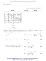
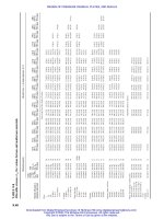
Values of L
10h
in hours as function of speed n and load
ratio ðC=F ¼ C=PÞ are given in Fig. 23-53.
f
L
¼
C
F
f
n
ð23-180aÞ
C ¼
f
L
f
n
F ¼
f
L
f
n
P ð23-180bÞ
where
F ¼ P
f
L
¼ index of dynamic stressing
f
n
¼ speed factor
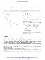
Refer to Fig. 23-56.
Particular Formula
DESIGN OF BEARINGS AND TRIBOLOGY
23.95
Downloaded from Digital Engineering Library @ McGraw-Hill (www.digitalengineeringlibrary.com)
Copyright © 2004 The McGraw-Hill Companies. All rights reserved.
Any use is subject to the Terms of Use as given at the website.
DESIGN OF BEARINGS AND TRIBOLOGY
FIGURE 23-53 Nomogram chart f or determining c/p for ball and roller bearings (ISO-R281) (Note: Information on the
calculation of load rating C and equivalent load P can be obtained from ISO Recommendation R281. Values of C for various
types of bearing can be obtained from the bearing manufacturers.)
ROLLER BEARINGS
BALL BEARINGS
Speed
rev/min
Load
ratio
C/P
Rating life
hours
L
h
Million
revolutions
L=L
10
Speed
rev/min
Load
ratio
C/P
Rating life
hours
L
h
Million
revolutions
L=L
10
30000
20000
15000
10000
9000
8000
7000
6000
5000
4000
3000
2000
1800
1500
1200
1000
900
800
700
600
500
400
300
200
150
100
90
80
70
60
50
40
30
20
1.0
1.5
2
3
4
5
6
7
8
9
10
15
20
30
40
60000
50000
40000
30000
20000
10000
8000
6000
5000
4000
3000
2000
1000
800
600
500
400
300
200
100
80
60
50
40
30
20
10
8
6
5
4
3
2
1.0
200
300
400
500
600
700
800
900
1000
1500
2000
3000
4000
5000
6000
7000
8000
9000
10000
15000
20000
30000
40000
50000
60000
70000
80000
90000
100000
150000
200000
300000
30000
20000
15000
10000
9000
8000
7000
6000
5000
4000
3000
2000
1800
1500
1200
1000
900
800
700
600
500
400
300
200
150
100
90
80
70
60
50
40
30
20
1.0 1.0
2
3
4
6
8
2
1.5
10
20
30
40
50
60
80
100
200
300
400
500
600
7
6
5
3
4
800
1000
2000
3000
4000
5000
6000
8000
10000
20000
8
9
10
15
20
30
40
30000
40000
50000
60000
80000
100000
200000
300000
200000
150000
100000
90000
80000
70000
60000
50000
40000
30000
20000
15000
10000
9000
8000
7000
6000
5000
4000
3000
2000
1500
1000
900
800
700
600
500
400
300
200
23.96 CHAPTER TWENTY-THREE
Downloaded from Digital Engineering Library @ McGraw-Hill (www.digitalengineeringlibrary.com)
Copyright © 2004 The McGraw-Hill Companies. All rights reserved.
Any use is subject to the Terms of Use as given at the website.
DESIGN OF BEARINGS AND TRIBOLOGY
The value of index of dynamic stressing, f
L
, can be
obtained from Eq. (23-179b)
f
L
¼
m
ffiffiffiffiffiffiffiffi
L
h
500
r
ð23-181aÞ
For a life of 500 h, f
L
¼ 1
Refer to Table 23-43 for f
L
of ball bearings
Refer to Table 23-44 for f
L
of roller bearings and to
Table 23-58
Particular Formula
TABLE 23-43
Index of dynamic stressing f
L
for ball bearings for use in Eq. (23-180) f
L
¼
3
ffiffiffiffiffiffiffiffiffiffiffiffiffiffiffi
L
h
=500
p
L
h
L
h
L
h
L
h
L
h
L
h
L
h
hours f
L
hours f
L
hours f
L
hours f
L
hours f
L
hours f
L
hours f
L
100 0.585 300 0.843 700 1.120 1750 1.520 4500 2.08 10000 2.71 30000 3.91
105 0.595 310 0.852 720 1.130 1800 1.535 4600 2.10 10500 2.76 31000 3.96
110 0.604 320 0.861 740 1.140 1850 1.545 4700 2.11 11000 2.80 32000 4.00
115 0.613 330 0.870 760 1.150 1900 1.560 4800 2.13 11500 2.85 33000 4.04
120 0.622 340 0.879 780 1.160 1950 1.575 4900 2.14 12000 2.85 34000 4.08
125 0.631 350 0.888 800 1.170 2000 1.590 5000 2.15 12500 2.93 35000 4.12
130 0.639 360 0.896 820 1.180 2100 1.615 5200 2.18 13000 2.96 36000 4.16
135 0.647 370 0.905 840 1.190 2200 1.640 5400 2.21 13500 3.00 37000 4.20
140 0.654 380 0.913 860 1.200 2300 1.665 5600 2.24 14000 3.04 38000 4.24
145 0.662 390 0.921 880 1.205 2400 1.690 5800 2.27 14500 3.07 3900 4.27
150 0.670 400 0.928 900 1.215 2500 1.710 6000 2.29 15000 3.11 40000 4.31
155 0.677 410 0.936 920 1.225 2600 1.730 6200 2.32 15500 3.14 41000 4.35
160 0.684 420 0.944 940 1.235 2700 1.755 6400 2.34 16000 3.18 42000 4.38
165 0.691 430 0.951 960 1.245 2800 1.775 6600 2.37 16500 3.21 43000 4.42
170 0.698 440 0.959 980 1.260 2900 1.795 6800 2.39 17000 3.24 44000 4.45
175 0.705 450 0.966 1000 1.260 3000 1.815 7000 2.41 17500 3.27 45000 4.48
180 0.712 460 0.973 1050 1.280 3100 1.835 7200 2.43 18000 3.30 46000 4.51
185 0.718 470 0.980 1100 1.300 3200 1.855 7400 2.46 18500 3.33 47000 4.55
190 0.724 480 0.987 1150 1.320 3300 1.875 7600 2.48 19000 3.36 48000 4.58
195 0.731 490 0.994 1200 1.340 3400 1.895 7800 2.50 19500 3.39 49000 4.61
200 0.737 500 1.000 1250 1.360 3500 1.910 8000 2.52 20000 3.42 50000 4.64
210 0.749 520 1.015 1300 1.375 3600 1.930 8200 2.54 21000 3.48 55000 4.80
220 0.761 540 1.025 1350 1.395 3700 1.950 8400 2.56 22000 3.53 60000 4.94
230 0.772 560 1.040 1400 1.410 3800 1.965 8600 2.58 23000 3.58 65000 5.07
240 0.783 580 1.050 1450 1.425 3900 1.985 8800 2.60 24000 3.63 70000 5.19
250 0.794 600 1.065 1500 1.445 4000 2.000 9000 2.62 25000 3.68 75000 5.30
260 0.804 620 1.075 1550 1.460 4100 2.020 9200 2.64 26000 3.73 80000 5.43
270 0.814 640 1.085 1600 1.475 4200 2.030 9400 2.66 27000 3.78 85000 5.55
280 0.824 660 1.100 1650 1.490 4300 2.050 9600 2.68 28000 3.82 90000 5.65
290 0.834 680 1.110 1700 1.505 4400 2.070 9800 2.70 29000 3.87 100000 5.85
DESIGN OF BEARINGS AND TRIBOLOGY
23.97
Downloaded from Digital Engineering Library @ McGraw-Hill (www.digitalengineeringlibrary.com)
Copyright © 2004 The McGraw-Hill Companies. All rights reserved.
Any use is subject to the Terms of Use as given at the website.
DESIGN OF BEARINGS AND TRIBOLOGY
The value of speed factor, f
n
, can be obtained from
Eq. (23-179b)
The equivalent dynamic load for deep groove ball
bearings with increased radial clearance
f
n
¼
m
ffiffiffiffiffiffiffiffi
33
1
3
n
s
¼
m
ffiffiffiffiffiffiffiffi
100
3n
r
ð23-181bÞ
For a speed factor of n ¼ 33
1
3
min, f
n
¼ 1
Refer to Table 23-45 for f
n
of ball bearings
Refer to Table 23-46 for f
n
of roller bearings
F
e
¼ P
a
¼ XF
r
þ YF
a
ð23-182Þ
Particular Formula
TABLE 23-44
Index of dynamic stressing f
L
for roller bearings for use in Eq. (23-180) f
L
¼
10=3
ffiffiffiffiffiffiffiffiffiffiffiffiffiffiffi
L
h
=500
p
L
h
L
h
L
h
L
h
L
h
L
h
L
h
hours f
L
hours f
L
hours f
L
hours f
L
hours f
L
hours f
L
hours f
L
100 0.617 300 0.858 700 1.105 1750 1.455 4500 1.935 10000 2.46 30000 3.42
105 0.626 310 0.866 720 1.115 1800 1.470 4600 1.945 10500 2.49 31000 3.45
110 0.635 320 0.875 740 1.125 1850 1.480 4700 1.960 11000 2.53 32000 3.48
115 0.643 330 0.883 760 1.135 1900 1.490 4800 1.970 11500 2.56 33000 3.51
120 0.652 340 0.891 780 1.145 1950 1.505 4900 1.985 12000 2.59 34000 3.55
125 0.660 350 0.889 800 1.150 2000 1.515 5000 2.00 12500 2.63 35000 3.58
130 0.665 360 0.906 820 1.160 2100 1.540 5200 2.02 13000 2.66 36000 3.61
135 0.675 370 0.914 840 1.170 2200 1.560 5400 2.04 13500 2.69 37000 3.64
140 0.683 380 0.921 860 1.180 2300 1.580 5600 2.06 14000 2.72 39000 3.67
145 0.690 390 0.928 880 1.185 2400 1.600 5800 2.09 14500 2.75 39000 3.70
150 0.697 400 0.935 900 1.190 2500 1.620 6000 2.11 15000 2.77 40000 3.72
155 0.704 410 0.942 920 1.200 2600 1.640 6200 2.13 15500 2.80 41000 3.75
160 0.710 420 0.949 940 1.210 2700 1.660 6400 2.15 16000 2.83 42000 3.78
165 0.717 430 0.956 960 1.215 2800 1.675 6600 2.17 16500 2.85 43000 3.80
170 0.723 440 0.962 980 1.225 2900 1.695 6800 2.19 17000 2.88 44000 2.83
175 0.730 450 0.969 1000 1.230 3000 1.710 7000 2.21 17500 2.91 45000 3.86
180 0.736 460 0.975 1050 1.250 3100 1.730 7200 2.23 18000 2.93 46000 3.88
185 0.742 470 0.982 1100 1.270 3200 1.755 7400 2.24 18500 2.95 47000 3.91
190 0.748 480 0.994 1150 1.285 3300 1.760 7600 2.26 19000 2.98 48000 3.93
195 0.754 490 0.998 1200 1.300 3400 1.775 7800 2.28 19500 3.00 49000 3.96
200 0.760 500 1.000 1250 1.315 3500 1.795 8000 2.30 20000 3.02 50000 3.98
210 0.771 520 1.010 1300 1.330 3600 1.810 8200 2.31 21000 3.07 55000 4.10
220 0.782 540 1.025 1350 1.345 3700 1.825 8400 2.33 22000 3.11 60000 4.20
230 0.792 560 1.035 1400 1.360 3800 1.840 8608 2.35 23000 3.15 65000 4.30
240 0.802 580 1.045 1450 1.375 3900 1.850 8800 2.36 24000 3.19 70000 4.40
250 0.812 600 1.055 1500 1.390 4000 1.865 9000 2.38 25000 3.23 75000 4.50
260 0.822 620 1.065 1550 1.405 4100 1.880 9200 2.40 26000 3.27 80000 4.58
270 0.831 640 1.075 1600 1.420 4200 1.895 9400 2.41 27000 3.31 85000 4.66
280 0.840 660 1.085 1650 1.430 4300 1.905 9600 2.43 28000 3.35 90000 4.75
290 0.849 680 1.095 1700 1.445 4400 1.920 9800 2.44 29000 3.38 100000 4.90
150000 5.54
200000 6.03
23.98 CHAPTER TWENTY-THREE
Downloaded from Digital Engineering Library @ McGraw-Hill (www.digitalengineeringlibrary.com)
Copyright © 2004 The McGraw-Hill Companies. All rights reserved.
Any use is subject to the Terms of Use as given at the website.
DESIGN OF BEARINGS AND TRIBOLOGY
TABLE 23-45
Speed factor f
n
for ball bearings for use in Eq. (23-180) f
n
¼
3
ffiffiffiffiffiffiffiffiffiffiffiffiffi
33
1
3
=n
q
Speed, Speed Speed, Speed Speed, Speed Speed, Speed Speed, Speed Speed, Speed
n, rpm factor, f
n
n, rpm factor, f
n
n, rpm factor, f
n
n, rpm factor, f
n
n, rpm factor, f
n
n, rpm factor, f
n
10 1.494 60 0.822 250 0.511 900 0.333 4000 0.203 15,000 0.131
11 1.447 62 0.813 260 0.504 920 0.331 4100 0.201 15,500 0.129
12 1.405 64 0.805 270 0.498 940 0.329 4200 0.199 16,000 0.128
13 1.369 66 0.797 280 0.492 960 0.326 4300 0.198 16,500 0.126
14 1.335 68 0.788 290 0.487 980 0.324 4400 0.196 17,000 0.125
15 1.305 70 0.781 300 0.481 1000 0.322 4500 0.195 17,500 0.124
16 1.277 72 0.774 310 0.476 1050 0.317 4600 0.193 18,000 0.123
17 1.252 74 0.767 320 0.471 1100 0.312 4700 0.192 18,500 0.122
18 1.225 76 0.760 330 0.466 1150 0.302 4800 0.191 19,000 0.121
19 1.206 78 0.753 340 0.461 1200 0.303 4900 0.190 19,500 0.120
20 1.186 80 0.747 350 0.457 1250 0.299 5000 0.188 20,000 0.119
21 1.166 82 0.741 360 0.453 1300 0.295 5200 0.186 21,000 0.117
22 1.148 84 0.735 370 0.448 1350 0.291 5400 0.183 22,000 0.115
23 1.132 86 0.729 380 0.444 1400 0.288 5600 0.181 23:000 0.113
24 1.116 88 0.724 390 0.441 1450 0.284 5800 0.179 24,000 0.112
25 1.100 90 0.718 400 0.437 1500 0.281 6000 0.177 25,000 0.110
26 1.089 92 0.713 410 0.433 1550 0.278 6200 0.175 26,000 0.109
27 1.071 94 0.708 420 0.430 1600 0.275 6400 0.173 27,000 0.107
28 1.060 96 0.703 430 0.426 1650 0.272 6600 0.172 28,000 0.106
29 1.048 98 0.698 440 0.423 1700 0.270 6800 0.170 29,000 0.105
30 1.036 100 0.693 450 0.420 1750 0.267 7000 0.168 30,000 0.104
31 1.025 105 0.692 460 0.417 1800 0.265 7200 0.167 32,000 0.101
32 1.014 110 0.672 470 0.414 1850 0.262 7400 0.165 34,000 0.0993
33 1.003 115 0.662 480 0.411 1900 0.260 7600 0.164 36,000 0.0975
34 0.993 120 0.652 490 0.408 1950 0.258 7800 0.162 38,000 0.0957
35 0.984 125 0.644 500 0.406 2000 0.255 8000 0.611 40,000 0.0941
36 0.975 130 0.635 520 0.400 2100 0.251 8200 0.160 42,000 0.0926
37 0.966 135 0.627 540 0.395 2200 0.247 8400 0.158 44,000 0.0912
38 0.958 140 0.620 560 0.390 2300 0.244 8600 0.157 46,000 0.0898
39 0.949 145 0.613 580 0.386 2400 0.248 8800 0.156 50,000 0.0874
40 0.941 150 0.606 600 0.382 2500 0.237 9000 0.155
41 0.933 155 0.599 620 0.378 2600 0.234 9200 0.154
42 0.926 160 0.583 640 0.374 2700 0.231 9400 0.153
43 0.919 165 0.586 660 0.370 2800 0.228 9600 0.152
44 0.912 170 0.581 680 0.366 2900 0.226 9800 0.150
45 0.905 175 0.575 700 0.363 3000 0.223 10,000 0.149
46 0.898 180 0.570 720 0.359 3100 0.221 10,500 0.147
47 0.892 185 0.565 740 0.356 3200 0.218 11,000 0.145
48 0.585 190 0.560 760 0.353 3300 0.216 11,500 0.143
49 0.880 195 0.555 780 0.350 3400 0.214 12,000 0.141
50 0.874 200 0.550 800 0.347 3500 0.212 12,500 0.139
52 0.863 210 0.541 820 0.344 3600 0.210 13,000 0.137
54 0.851 220 0.533 840 0.341 3700 0.208 13,500 0.135
56 0.841 230 0.525 860 0.339 3800 0.206 14,000 0.134
58 0.831 240 0.518 880 0.336 3900 0.205 14,500 0.132
DESIGN OF BEARINGS AND TRIBOLOGY
23.99
Downloaded from Digital Engineering Library @ McGraw-Hill (www.digitalengineeringlibrary.com)
Copyright © 2004 The McGraw-Hill Companies. All rights reserved.
Any use is subject to the Terms of Use as given at the website.
DESIGN OF BEARINGS AND TRIBOLOGY
TABLE 23.46
Speed factor f
n
for roller bearings for us in Eq. (23-180) f
n
¼
10=3
ffiffiffiffiffiffiffiffiffiffiffiffiffi
33
1
3
=n
q
Speed, Speed Speed, Speed Speed, Speed Speed, Speed Speed, Speed Speed, Speed
n, rpm factor, f
n
n, rpm factor, f
n
n, rpm factor, f
n
n, rpm factor, f
n
n, rpm factor, f
n
n, rpm factor, f
n
10 1.435 60 0.838 250 0.546 900 0.372 4000 0.238 15000 0.160
11 1.395 62 0.830 260 6.540 920 0.370 4100 0.236 15500 0.158
12 1.359 64 0.822 270 0.534 940 0.367 4200 0.234 16000 0.157
13 1.326 66 0.815 280 0.528 960 0.365 4300 0.233 16500 0.156
14 1.297 68 0.807 290 0.523 980 0.363 4400 0.231 17000 0.154
15 1.271 70 0.800 300 0.517 1000 0.361 4500 0.230 17500 0.153
16 1.246 72 0.794 310 0.512 1050 0.355 4600 0.228 18000 0.152
17 1.224 74 0.787 320 0.507 1100 0.350 4700 0.227 18500 0.150
18 1.203 76 0.781 330 0.503 1150 0.346 4800 0.225 19000 0.149
19 1.184 78 0.775 340 0.498 1200 0.341 4900 0.224 19500 0.148
20 1.166 80 0.769 350 0.494 1250 0.337 5000 0.222 20000 0.147
21 1.149 82 0.763 360 0.490 1300 0.333 5200 0.220 21000 0.145
22 1.133 84 0.758 370 0.486 1350 0.329 5400 0.217 22000 0.143
23 1.118 86 0.753 380 0.482 1400 0.336 5600 0.215 23000 0.141
24 1.104 88 0.747 390 0.478 1450 0.322 5800 0.213 24000 0.139
25 1.090 90 0.742 400 0.475 1500 0.319 6000 0.211 25000 0.137
26 1.077 92 0.737 410 0.471 1550 0.316 6200 0.209 26000 0.136
27 1.065 94 0.733 420 0.467 1600 0.313 6400 0.207 27000 0.134
28 1.054 96 0.728 430 0.464 1650 0.310 6600 0.205 28000 0.133
29 1.0411 98 0.724 440 0.461 1700 0.307 6800 0.203 29000 0.131
30 1.032 100 0.719 450 0.458 1750 0.305 7000 0.201 30000 0.130
31 1.022 105 0.709 460 0.455 1800 0.302 7200 0.199 32000 0.127
32 1.012 110 0.699 470 0.452 1850 0.300 7400 0.198 34000 0.125
33 1.003 115 0.690 480 0.449 1900 0.297 7600 0.196 36000 0.123
34 0.994 120 0.681 490 0.447 1950 0.295 7800 0.195 38000 0.121
35 0.986 125 0.673 500 0.444 2000 0.293 8000 0.137 40000 0.119
36 0.977 130 0.665 520 0.439 2100 0.289 8200 0.192 42000 0.117
37 0.969 135 0.657 540 0.434 2200 0.285 8400 0.190 44000 0.116
38 0.962 140 0.650 560 0.429 2300 0.281 8600 0.189 46000 0.114
39 0.954 145 0.643 580 0.425 2400 0.274 8800 0.188 50000 0.111
40 0.947 150 0.637 600 0.420 2500 0.274 9000 0.187
41 0.940 155 0.631 620 0.416 2600 0.271 9200 0.185
42 0.933 160 0.625 640 0.412 2700 0.268 9400 0.184
43 0.927 165 0.619 660 0.408 2800 0.265 9600 0.183
44 0.920 170 0.613 680 0.405 2900 0.262 9800 0.182
45 0.914 175 0.608 700 0.401 3000 0.259 10000 0.181
46 0.908 180 0.603 720 0.398 3100 0.257 10500 0.178
47 0.902 185 0.598 740 0.395 3200 0.254 11000 0.176
48 0.896 190 0.593 760 0.391 3300 0.252 11500 0.173
49 0.891 195 0.589 780 0.388 3400 0.250 12000 0.171
50 0.896 200 0.584 800 0.385 3500 0.248 12500 0.169
52 0.875 210 0.576 820 0.383 3600 0.246 13000 0.167
54 0.865 220 0.568 840 0.380 3700 0.243 13500 0.165
56 0.856 230 0.560 860 0.377 3800 0.242 14000 0.163
58 0.847 240 0.553 880 0.375 3900 0.240 14500 0.162
23.100 CHAPTER TWENTY-THREE
Downloaded from Digital Engineering Library @ McGraw-Hill (www.digitalengineeringlibrary.com)
Copyright © 2004 The McGraw-Hill Companies. All rights reserved.
Any use is subject to the Terms of Use as given at the website.
DESIGN OF BEARINGS AND TRIBOLOGY
LIFE ADJUSTMENT FACTORS
An adjusted fatigue life equation for a reliability of
(100-n) percent
An approximate equation for adjusted factor a
1
,
which accounts for reliability, R, is calculated from
the Weibull distribution.
The adjusted fatigue life for non-conventional materi-
als and operating conditions.
For values of X and Y , refer to Table 23-39 and also
to bearing tables given in FAG catalogue. For values
of X and Y of deep groove ball bearings with
increased radial clearance, refer to Table 23-47b.
L
10a
¼ a
2
a
3
L
10
ð23-183Þ
where
a
2
¼ life adjustment factor for materials
¼ 3 for radial ball bearings of good quality as per
AFBMA
¼ 0.2 to 2.0 for normal bearing materials
¼ 2.0 for most common material, AISI 52100
a
3
¼ life adjustment factor for application operating
conditions
¼ 1 for well and adequately lubricated bearings
< 1 for other adverse lubricating conditions and
temperatures.
The standard does not yet include values of a
3
TABLE 23-47a
Values of radial factors X and thrust factors Y for deep groove ball bearings with increase In radial clearance
Normal Bearing Standard clearance Bearing clearance C3
a
Bearing clearance C4
a
F
a
F
r
e
F
a
F
r
> e
F
a
F
r
e
F
a
F
r
> e
F
a
F
r
e
F
a
F
r
> e
f
o
F
a
C
o
e XYXYe XYXYe XYXY
0.3 0.22 1 0 0.56 2.0 0.32 1 0 0.46 1.70 0.40 1 0 0.44 1.40
0.5 0.24 1 0 0.56 1.8 0.35 1 0 0.46 1.56 0.43 1 0 0.44 1.31
0.9 0.28 1 0 0.56 1.6 0.39 1 0 0.46 1.41 0.45 1 0 0.44 1.23
1.6 0.32 1 0 0.56 1.4 0.43 1 0 0.46 1.27 0.48 1 0 0.44 1.16
3.0 0.36 1 0 0.56 1.2 0.48 1 0 0.46 1.14 0.52 1 0 0.44 1.08
6.0 0.43 1 0 0.56 1.0 0.54 1 0 0.46 1.00 0.56 1 0 0.44 1.00
a
C
3
, C
4
Standard for a radial clearance that is larger than normal.
Values of factor f
a
are given in Table 23-47b
Particular Formula
DESIGN OF BEARINGS AND TRIBOLOGY
23.101
Downloaded from Digital Engineering Library @ McGraw-Hill (www.digitalengineeringlibrary.com)
Copyright © 2004 The McGraw-Hill Companies. All rights reserved.
Any use is subject to the Terms of Use as given at the website.
DESIGN OF BEARINGS AND TRIBOLOGY
TABLE 23-47b
Factor f
o
for deep groove ball bearings for use in Table
23-47a
Factor f
o
Bore Bearing series
reference
number 160 60 62 63 64
00 — 12.4 12.1 11.3 —
01 — 13.0 12.2 11.1 —
02 13.9 13.9 13.1 12.1 —
03 14.3 14.3 13.1 12.2 10.9
04 14.9 13.9 13.1 12.1 11.0
05 15.4 14.5 13.8 12.4 12.1
06 15.2 14.8 13.8 13.0 12.2
07 15.6 14.8 13.8 13.1 12.1
08 15.9 15.2 14.0 13.0 12.2
09 15.9 15.4 14.1 13.0 12.1
10 16.1 15.6 14.3 13.0 12.2
11 16.1 15.4 14.3 12.9 12.2
12 16.3 15.5 14.3 13.1 12.3
13 16.4 15.7 14.3 13.2 12.3
14 16.2 15.5 14.4 13.2 12.1
15 16.4 15.7 14.7 13.2 12.2
16 16.4 15.6 14.6 13.2 12.3
17 16.4 15.7 14.7 13.1 12.3
18 16.3 15.6 14.5 13.9 12.2
19 16.5 15.7 14.4 13.9
20 16.4 15.9 14.4 13.8
21 16.3 15.8 14.3 13.7
22 16.3 15.6 14.3 13.8
24 16.4 15.9 14.8 13.5
26 16.4 15.8 14.5 13.6
28 16.4 16.0 14.8 13.6
30 16.4 16.0 15.2 13.7
32 16.4 16.0 15.2 13.9
34 16.4 15.7 15.3 13.9
36 16.3 15.6 15.3 13.9
38 16.4 15.8 15.0 14.0
40 16.3 15.6 15.3 14.1
44 16.3 15.6 15.2 14.1
48 16.4 15.8 15.2 14.2
52 16.4 15.7 15.2
56 16.4 15.9 15.3
60 16.4 15.7
64 16.4 15.9
68 16.3 15.8
72 16.4 15.9
76 16.5 15.9
TABLE 23-48
Life adjustment factor for reliability a
1
Reliability R, % L
n
Adjustment factor, a
1
90 L
10
1
95 L
5
0.65
96 L
4
0.53
97 L
3
0.44
98 L
2
0.33
99 L
1
0.21
Note: These values of a
1
and a
2
have to be used judiciously and
designers are advised to consult manufacturer’s Catalogue
23.102 CHAPTER TWENTY-THREE
Downloaded from Digital Engineering Library @ McGraw-Hill (www.digitalengineeringlibrary.com)
Copyright © 2004 The McGraw-Hill Companies. All rights reserved.
Any use is subject to the Terms of Use as given at the website.
DESIGN OF BEARINGS AND TRIBOLOGY
From Eq. (23-177a), an adjusted fatigue life equation
taking into consideration adjustment factors a
1
, a
2
and a
3
, and for a failure probability of n as per
ISO 281
An adjusted fatigue life equation, which accounts for
variation in vibration and shock, speed, environment,
etc in addition to adjustment factors a
1
, a
2
and a
3
From Eq. (23-186a), the basic equivalent load rating,
which accounts for application factor K
a
, and adjust-
ment factors a
1
, a
2
and a
3
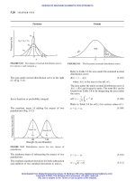
Fig. 23-54 shows the plot of relative life vs probability
of failure in percent. L
10
life (also called as B10 life or
minimum life), which indicates a 10% probability of
failure, i.e. 90% of the loaded bearings will survive
beyond this life, is taken as reference. L
50
in Fig.
23-54 indicates median life with a 50% probability
of failure, which is also known as average life. From
Fig. 23-54 it can be seen that L
50
% 5L
10
, which
indicates only 50% of the bearings will survive this
longer life.
For life curves of ball bearings as per SKF and New
Departure (ND) and Needle-bearings
L
na
¼ a
1
a
2
a
3
C
F
m
¼ a
1
a
2
a
3
L ð23-184aÞ
where L in millions of revolutions
L
hna
¼ a
1
a
2
a
3
L
h
ð23-184bÞ
where L
h
in h
L ¼ a
1
a
2
a
3
C
K
a
F
m
ð23-185Þ
where L in 10
6
revolutions
K
a
¼ application factor taken from Table 23-49
C ¼ K
a
F
L
a
1
a
2
a
3
1=m
ð23-186Þ
where L in 10
6
revolutions
Refer to Fig. 23-55
Particular Formula
TABLE 23-49
Load application factor K
a
for use in Eqs. (23-185) and (23-186)
Operating conditions Applications K
a
Precision gearing 1.0–1.1
Commercial gearing 1.1–1.3
Applications with poor bearing seals 1.2
Smooth operation free from shock Machinery with no impact:
Electric motors, machine tools, air conditioners 1–1.2
Normal operation Machinery with light impact:
Air blowers, compressors, elevators, cranes, paper making machines 1.2–1.5
Operation accompanied Machinery with moderate impact:
by shock and vibration Construction machines crushers, vibration screens, rolling mills 1.5–3.0
DESIGN OF BEARINGS AND TRIBOLOGY
23.103
Downloaded from Digital Engineering Library @ McGraw-Hill (www.digitalengineeringlibrary.com)
Copyright © 2004 The McGraw-Hill Companies. All rights reserved.
Any use is subject to the Terms of Use as given at the website.
DESIGN OF BEARINGS AND TRIBOLOGY
L
10
L
50
1
0102030405060
Probability of failure, percent
70 80 90 100
5
10
Relative fatigue life
15
20
FIGURE 23-54 Typical life distribution in rolling bearings. (Courtesy: SKF Industries, Inc.)
ND
T-Needle
SKF
0•2
500 1,000 2,000 3,000 5,000
Life of Bearing, Hours
10,000 20,000 50,000
0•3
0•4
0•5
0•7
Load Factor K
l
1•0
1•5
2•0
2•5
FIGURE 23-55 Life curves of ball and needle bearings.
23.104 CHAPTER TWENTY-THREE
Downloaded from Digital Engineering Library @ McGraw-Hill (www.digitalengineeringlibrary.com)
Copyright © 2004 The McGraw-Hill Companies. All rights reserved.
Any use is subject to the Terms of Use as given at the website.
DESIGN OF BEARINGS AND TRIBOLOGY
BASIC DYNAMIC LOAD RATING OF
BEARINGS AS PER INDIAN STANDARDS
Radial Ball Bearing
The basic dynamic load rating for radial and angular
contact ball bearings.
C
r
¼ f
c
ði cos Þ
0:7
Z
2=3
ðD
w
Þ
1:8
ð23-187Þ
for D
w
25:4mm
where C
r
in N, D
w
in mm
C
r
¼ 3:647f
c
ði cos Þ
0:7
Z
2=3
ðD
w
Þ
1:4
ð23-188Þ
for D
w
> 25:4mm
where C
r
in N, D
w
in mm
For values of factor f
c
refer to Table 23-50.
Particular Formula
TABLE 23-50
Values of factor f
c
for radial ball bearings for use in Eqs. (23-187) and (23-188)
Factor, f
c
D
w
cos
D
pw
Single row radial contact groove ball
bearings and single and double row-
angular contact groove ball bearings
Double row radial
contact groove ball
bearings
Single row and
double row self-
aligning ball bearings
Single row radial contact
separable ball bearings
(magneto bearings)
0.05 46.7 44.2 17.3 16.2
0.06 49.1 46.5 18.6 17.4
0.07 51.1 48.4 19.9 18.5
0.08 52.8 50.0 21.1 19.5
0.09 54.3 51.4 22.3 20.6
0.10 55.5 52.6 33.4 21.5
0.12 57.5 54.5 25.6 23.4
0.14 58.8 55.7 27.7 25.3
0.16 59.6 56.5 29.7 27.1
0.18 59.9 56.8 31.7 28.8
0.20 59.9 56.8 33.5 30.5
0.22 59.6 56.5 35.2 32.1
0.24 59.0 55.9 36.8 33.7
0.26 58.2 55.1 38.2 35.2
0.28 57.1 54.1 39.4 36.6
0.30 56.0 53.0 40.3 37.8
0.32 54.6 51.8 40.9 38.9
0.34 53.2 50.4 41.2 39.8
0.36 51.7 48.9 41.3 40.4
0.38 50.0 47.4 41.0 40.8
0.40 48.4 45.8 40.4 40.9
Note: Values of f
c
for intermediate values of D
0
w
cos =D
pw
are obtained by linear interpolation. IS: 3824 (Part 1)–1983
DESIGN OF BEARINGS AND TRIBOLOGY 23.105
Downloaded from Digital Engineering Library @ McGraw-Hill (www.digitalengineeringlibrary.com)
Copyright © 2004 The McGraw-Hill Companies. All rights reserved.
Any use is subject to the Terms of Use as given at the website.
DESIGN OF BEARINGS AND TRIBOLOGY
The approximate rating life in millions of revolutions
for ball bearing
The equivalent radial load for radial and contact ball
bearings under combined constant radial and axial
loads
The basic rating life for a radial ball bearing which is
based statistically
Adjusted rating life
The adjusted rating life for a reliability of (100-n)
percent
The adjusted rating life for non-conventional materi-
als and operating conditions
The adjusted rating life for non-conventional materi-
als and operating conditions, and for a reliability of
(100-n) percent.
Radial roller bearings
The basic dynamic radial load rating of radial roller
bearings
The equivalent radial load for radial roller bearings
with 6¼ 08 under combined constant radial and
axial loads
The equivalent radial load for radial roller bearings
with 6¼ 08 and subjected to radial load only
The basic rating life in millions of revolutions for
radial roller bearings
For adjusted rating life for roller bearings
L
n
¼
C
P
3
ð23-189Þ
P
r
¼ XF
r
þ F
a
ð23-190Þ
For values of X and Y refer to Table 23-51.
L
10
¼
C
r
P
r
3
ð23-191Þ
where L
10
¼ basic rating life in millions of
revolutions (i.e., the number of revolutions
resulting in 10% failure).
The values of C
r
and P
r
shall be calculated in accor-
dance with Eqs. (23-187), (23-188), and (23-190).
L
n
¼ a
1
L
10
ð23-192Þ
L
10a
¼ a
2
a
3
L
10
ð23-193Þ
L
na
¼ a
1
a
2
a
3
L
10
ð23-194Þ
Refer to Table 23-48 for a
1
values
C
r
¼ f
c
ðiL
we
cos Þ
7=9
Z
3=4
D
29=27
we
ð23-195Þ
where C
r
in N, L
we
and D
we
in mm
For values of factor f
c
refer to Table 23-52.
P
r
¼ XF
r
þ YF
a
ð23-196Þ
For values of X and Y refer to Table 23-53.
P
r
¼ F
r
ð23-197Þ
L
10
¼
C
r
P
r
10=3
ð23-198Þ
The values of C
r
and P
r
are calculated in accordance
with Eqs. (23-195) to (23-197).
Refer to Eqs. (23-192) to (23-194) with suitable
modification.
Particular Formula
23.106 CHAPTER TWENTY-THREE
Downloaded from Digital Engineering Library @ McGraw-Hill (www.digitalengineeringlibrary.com)
Copyright © 2004 The McGraw-Hill Companies. All rights reserved.
Any use is subject to the Terms of Use as given at the website.
DESIGN OF BEARINGS AND TRIBOLOGY
TABLE 23-51
Factors X and Y for radial ball bearings for use in Eq. (23-190)
Single-row bearings Double-row bearings
F
a
F
r
e
F
a
F
r
! e
F
a
F
r
e
F
a
F
r
! e
‘Relative axial load’
a
XYXYXYXYe
Radial contact groove ball bearings
F
a
C
or
F
a
iZD
2
w
0.014 0.172 1 0 0.56 2.30 1 0 0.56 2.30 0.19
0.028 0.345 1.99 1.99 0.22
0.056 0.689 1.71 1.71 0.26
0.084 1.30 1.55 1.55 0.28
0.11 1.38 1.45 1.45 0.30
0.17 2.07 1.31 1.31 0.34
0.28 3.45 1.15 1.15 0.38
0.42 5.17 1.04 1.04 0.42
0.56 6.89 1.00 1.00 0.44
Angular contact groove ball bearings
iF
a
C
or
F
a
ZD
2
w
58 0.014 0.172 1 0 For this type use the 1 2.78 0.78 3.74 0.23
0.028 0.345 X, Y and e values 2.40 3.23 0.26
0.056 0.689 applicable to single 2.07 2.78 0.30
0.085 1.03 row radial contact 1.87 2.52 0.34
0.11 1.38 groove ball bearings 1.75 2.36 0.86
0.17 2.07 1.58 2.13 0.40
0.28 3.45 1.39 1.87 0.45
0.42 5.17 1.26 1.69 0.50
0.56 6.89 1.21 1.63 0.52
108 0.014 0.172 1 0 0.46 1.88 1 2.18 0.75 3.06 0.29
0.029 0.345 1.71 1.98 2.78 0.32
0.057 0.689 1.52 1.76 2.47 0.36
0.086 1.03 1.41 1.63 2.29 0.38
0.11 1.38 1.34 1.55 2.18 0.40
0.17 2.07 1.23 1.42 2.00 0.44
0.29 3.45 1.10 1.27 1.79 0.49
0.43 5.17 1.01 1.17 1.64 0.54
0.57 6.89 1.00 1.16 1.63 0.54
158 0.015 0.172 1 0 0.46 1.47 1 1.65 0.72 2.39 0.38
0.029 0.345 1.40 1.57 2.28 0.40
0.058 0.689 1.30 1.40 2.11 0.43
0.087 1.03 1.23 1.38 2.00 0.46
0.12 1.38 1.19 1.34 1.93 0.47
0.17 2.07 1.12 1.26 1.82 0.50
0.29 3.45 1.02 1.14 1.66 0.55
0.44 5.17 1.00 1.12 1.63 0.56
0.58 6.89 1.00 1.12 1.63 0.56
208 — — 1 0 0.43 1.00 1 1.09 0.70 1.63 0.07
258 — — 0.41 0.87 0.92 0.67 1.41 0.68
308 — — 0.39 0.76 0.78 0.63 1.24 0.80
358 — — 0.37 0.66 0.66 0.60 1.07 0.95
408 — — 0.35 0.57 0.55 0.57 0.93 1.14
458 — — 0.33 0.50 0.47 0.54 0.81 1.34
Self-aligning ball bearings 1 0 0.40 0.4 cot 1 0.42 cot 0.65 0.65 cot 1.5 tan
Single row radial contact
separable ball bearings (magnetic
bearings)
1 0 0.52.5————0.2
Note: Values of X, Y and e for intermediate ‘relative axial loads’ and/or contact angles are obtained by linear interpolation. IS: 3824 (Part 1), 1983.
a
Permissible maximum value depends on bearing design (internal clearance and raceway groove depth).
23.107
Downloaded from Digital Engineering Library @ McGraw-Hill (www.digitalengineeringlibrary.com)
Copyright © 2004 The McGraw-Hill Companies. All rights reserved.
Any use is subject to the Terms of Use as given at the website.
DESIGN OF BEARINGS AND TRIBOLOGY
THRUST BEARINGS
Ball bearings
The basic dynamic axial load rating for a single-row,
single- or double-direction thrust ball bearing
ðC
a
Þ
¼908
¼ f
c
Z
2=3
D
1:8
w
ð23-199Þ
for D
w
25:4mm
ðC
a
Þ
6¼908
¼ f
c
ðcos Þ
0:7
tan Z
2=3
D
1:8
w
ð23-200Þ
for D
w
25:4mm
ðC
a
Þ
¼908
¼ 3:647f
c
Z
2=3
D
1:4
w
ð23-201Þ
for D
w
> 25:4mm
ðC
a
Þ
6¼908
¼ 3:647f
c
ðcos Þ
0:7
tan Z
2=3
D
1:4
w
ð23-202Þ
for D
w
> 25:4mm
where C
a
in N, D
w
in mm
For various values of f
c
refer to Table 23-54.
Z ¼ number of balls carrying load in one direction.
TABLE 23-52
Values of f
c
for radial roller
bearings for use in Eq. (23.195)
D
w
cos
D
pw
f
c
0.01 52.1
0.02 60.8
0.03 66.5
0.04 70.7
0.05 74.1
0.06 76.9
0.07 79.2
0.08 81.2
0.09 82.8
0.10 84.2
0.12 86.4
0.14 87.7
0.16 88.5
0.18 88.8
0.20 88.7
0.22 88.2
0.24 87.5
0.26 86.4
0.28 85.2
0.30 83.8
Note: Values of f
c
for intermediate value
of D
w
cos =D
w
are obtained by linear
interpolation. IS: 3824 (Part 2) 1983.
TABLE 23-53
Values of factors X and Y for radial roller bearings for use in Eq. (23-196)
F
a
F
r
e
F
a
F
r
> e
Bearing type XY XY e
Single-row 1 0 0.4 0:4cot 1:5tan
6¼ 0
Double-row 1 0:45 cot 0.67 0:67 cot 1:5 tan
6¼ 0
IS: 3824 (Part 2) 1983.
Particular Formula
23.108 CHAPTER TWENTY-THREE
Downloaded from Digital Engineering Library @ McGraw-Hill (www.digitalengineeringlibrary.com)
Copyright © 2004 The McGraw-Hill Companies. All rights reserved.
Any use is subject to the Terms of Use as given at the website.
DESIGN OF BEARINGS AND TRIBOLOGY
Bearings with two or more rows of balls
The basic dynamic axial load rating for thrust ball
bearings with two or more rows of similar balls
carrying load in the same direction
C
a
¼ðZ
1
þ Z
2
þÁÁÁþZ
n
Þ
Â
Z
1
C
a1
10=3
þ
Z
2
C
a2
10=3
"
þÁÁÁþ
Z
n
C
an
10=3
#
À3=10
ð23-203Þ
a
TABLE 23-54
Values of factor f
c
for thrust ball bearings for use in Eqs. (23-199) to (23-202)
f
c
D
w
D
pw
f
c
¼ 908
D
w
cos
D
pw
¼ 458 ¼ 608 ¼ 758
0.01 36.7 0.01 42.1 39.2 37.3
0.02 45.2 0.02 51.7 49.1 45.9
0.03 51.1 0.03 58.2 54.2 51.7
0.04 55.7 0.04 63.3 58.9 56.1
0.05 59.5 0.05 67.3 61.6 59.7
0.06 62.9 0.06 70.7 65.8 62.7
0.07 65.8 0.07 73.5 68.4 65.2
0.08 68.5 0.08 75.9 70.7 67.3
0.09 71.0 0.09 78.0 72.6 69.2
0.10 73.3 0.10 79.7 74.2 70.7
0.12 77.4 0.12 82.3 76.6
0.14 81.1 0.14 84.1 78.3
0.16 84.4 0.16 85.1 79.2
0.18 87.4 0.18 85.5 79.6
0.20 90.2 0.20 85.4 79.5
0.22 92.8 0.22 84.9
0.24 95.3 0.24 84.0
0.26 97.6 0.26 82.8
0.28 99.8 0.28 81.3
0.30 101.9 0.30 79.6
0.32 103.9
0.34 105.8
Note: For thrust bearings >458, values for ¼ 458 are shown to permit interpolation of values for between 458 and 608. IS: 3824 (Part 3) 1983
Particular Formula
a
Note: The designers or bearing users are advised to refer to catalogues or standards in this regard or the bearing users should
consult the bearing manufacturers regarding the evaluation of equivalent load and life in case where bearing with ¼ 08 are
subjected to an axial load. The ability of radial roller bearings with ¼ 08 to support axial loads varies considerably with bearing
designer execution.
DESIGN OF BEARINGS AND TRIBOLOGY
23.109
Downloaded from Digital Engineering Library @ McGraw-Hill (www.digitalengineeringlibrary.com)
Copyright © 2004 The McGraw-Hill Companies. All rights reserved.
Any use is subject to the Terms of Use as given at the website.
DESIGN OF BEARINGS AND TRIBOLOGY
Dynamic equivalent axial load
The equivalent load for thrust ball bearings with
6¼ 908 under combined constant axial and radial
loads
The equivalent axial load for thrust bearing with
¼ 908 which can support axial loads only
Basic rating life
The basic rating life in millions of revolutions for a
thrust ball bearings
The load ratings C
a1
; C
a1
; ; C
an
for the rows with
Z
1
; Z
2
; ; Z
n
balls are calculated from appropriate
single row bearing formulae from Eqs. (23-199)
to (23-202), Values of f
c
for D
w
=D
pw
or ðD
w
cos Þ=
D
PW
and/or contact angle other than shown in
Table 23-54 are obtained by linear interpolation or
extrapolation.
P
a
¼ XF
r
þ YF
a
ð23-204Þ
For values of X and Y refer to Table 23-55.
P
a
¼ F
a
ð23-205Þ
L
10
¼
C
a
P
a
3
ð23-206Þ
The values of C
a
and P
a
are calculated in accordance
with Eqs. (23-199) to (23-205).
Particular Formula
TABLE 23-55
Values of factors X and Y for thrust ball bearings for use in Eq. (23-204)
Single direction bearings
a
Double direction bearings
F
a
F
r
> e
F
a
F
r
e
F
a
F
r
> e
XYXYXYe
458 0.66 1 1.18 0.59 0.66 1 1.25
508 0.73 1.37 0.57 0.73 1.49
558 0.81 1.60 0.56 0.81 1.79
608 0.92 1.90 0.55 0.92 2.17
658 1.06 2.30 0.54 1.06 2.68
708 1.28 2.90 0.53 1.28 3.43
758 1.66 3.89 0.52 1.66 4.67
808 2.43 5.86 0.52 2.43 7.09
858 4.80 11.75 0.51 4.80 14.29
6¼ 908 1:25 tan
1 À
2
3
sin
1
20
13
tan
1 À
1
3
sin
10
13
1 À
1
3
sin
1:25 tan
1 À
2
3
sin
11:25 tan
Note: For thrust bearings >458. Values for ¼ 458 are shown to permit interpolation of values for between 458 and 508.
a
F
a
=F
r
e is unsuitable for single direction bearings. IS: 3824 (Part 3) 1983.
23.110 CHAPTER TWENTY-THREE
Downloaded from Digital Engineering Library @ McGraw-Hill (www.digitalengineeringlibrary.com)
Copyright © 2004 The McGraw-Hill Companies. All rights reserved.
Any use is subject to the Terms of Use as given at the website.
DESIGN OF BEARINGS AND TRIBOLOGY
Adjusted rating life
The adjusted rating life of (100-n) percent
For other adjusted rating life with modification if
required
Roller bearings
The basic dynamic axial load rating for single row,
single- or double-direction thrust roller bearing
L
n
¼ a
1
L
10
ð23-192Þ
Refer to Table 23-48 for values of factor a
1
.
Refer to Eqs. (23-193) to (23-194).
ðC
a
Þ
¼908
¼ f
c
L
7=9
we
Z
3=4
D
29=27
we
ð23-207Þ
ðC
a
Þ
6¼908
¼ f
c
ðL
we
cos Þ
7=9
tan Z
3=4
D
29=27
we
ð23-208Þ
where C
a
in N, L
we
and D
we
in mm
For values of factor f
c
refer to Table 23-56.
Z ¼ number of rollers carrying load in one direction.
Particular Formula
TABLE 23-56
Values of factor f
c
for thrust roller bearings for use in Eqs. (23-207) and (23-208)
f
c
Factor f
c
D
wc
D
pw
¼ 908
D
w
cos
D
pw
¼ 508
a
¼ 658
b
¼ 808
c
0.01 105.4 0.01 109.7 107.1 105.6
0.02 122.9 0.02 127.8 124.7 123.0
0.03 134.5 0.03 139.5 136.2 134.3
0.04 143.4 0.04 148.3 144.7 142.8
0.05 150.7 0.05 155.2 151.5 149.4
0.06 156.9 0.06 160.9 157.0 154.9
0.07 162.4 0.07 165.6 161.6 159.4
0.08 167.2 0.08 169.5 165.5 163.2
0.09 171.7 0.09 172.8 168.7 166.4
0.10 175.7 0.10 175.5 171.4 169.0
0.12 183.0 0.12 179.7 175.4 173.0
0.14 189.4 0.14 182.3 177.9 175.5
0 16 195.1 0.16 183.7 179.3
0.18 200.3 0 18 184.1 179.7
0.20 205.0 0.20 183.7 179.3
0.22 209.4 0.22 182.6
0.24 213.5 0.24 180.9
0.26 217.3 0.26 178.7
0.28 220.9
0.30 224.3
a
Applicable for 458 <<608;
b
Applicable for 608 <<758;
c
Applicable for 758 <<908
Note: Values of f
c
for intermediate values of D
wc
=D
pw
or D
w
cos =D
pw
are obtained by linear interpolation. IS: 3824 (Part 4) 1983.
DESIGN OF BEARINGS AND TRIBOLOGY 23.111
Downloaded from Digital Engineering Library @ McGraw-Hill (www.digitalengineeringlibrary.com)
Copyright © 2004 The McGraw-Hill Companies. All rights reserved.
Any use is subject to the Terms of Use as given at the website.
DESIGN OF BEARINGS AND TRIBOLOGY
Bearing with two or more rows of rollers
The basic dynamic axial load rating for thrust roller
bearings with two or more rows of rollers carrying
load in the same direction
The equivalent axial load for thrust roller bearings
when 6¼ 908 under combined constant axial and
radial load
The equivalent axial load for thrust roller bearings
with ¼ 908 which can support only axial load
The basic rating life in millions of revolutions for
thrust roller bearings
Adjusted rating life
The Eqs. (23-192), (23-193) and (23-194) for adjusted
rating life with appropriate modification to suit the
roller thrust bearings are repeated here
Variable bearing load and speed
The mean affective load F
m
under varying load and
varying speed n
1
, n
2
, n
3
; ; n
i
at which the individual
loads F
1
, F
2
, F
3
; ; F
i
act.
C
a
¼ðZ
1
L
we1
þ Z
2
L
we2
þÁÁÁþZ
n
L
wen
Þ
Â
Z
1
L
we1
C
a1
9=2
þ
Z
2
L
we2
C
a2
9=2
"
þÁÁÁþ
Z
n
L
wen
C
an
9=2
#
À2=9
ð23-209Þ
where C
a
in N, L
we
and D
we
in mm
The load ratings C
a1
; C
a2
; ; C
an
for the rows with
Z
1
; Z
2
; ; Z
n
rollers of length L
we1
; L
we2
; ; L
wen
are calculated from the appropriate single row
bearing Eqs. (23-207) and (23-208).
P
a
¼ XF
r
þ YF
a
ð23-210Þ
For values of X and Y refer to Table 23-57.
P
a
¼ F
a
ð23-211Þ
L
10
¼
C
a
P
a
10=3
ð23-212Þ
The values of C
a
and P
a
are calculated in accordance
with Eqs. (23-207), (23-208), and (23-210).
L
n
¼ a
1
L
10
ð23-192Þ
L
10a
¼ a
2
a
3
L
10
ð23-193Þ
L
na
¼ a
1
a
2
a
3
L
10
ð23-194Þ
F
m
¼
m
ffiffiffiffiffiffiffiffiffiffiffiffiffiffiffiffiffiffiffiffiffiffiffiffiffiffiffiffiffiffiffiffiffiffiffiffiffiffiffiffiffiffiffiffiffiffiffiffiffiffiffiffiffiffiffiffiffiffiffiffiffiffiffiffiffiffiffiffiffiffiffi
F
m
1
n
1
þ F
m
2
n
2
þ F
m
3
n
3
þÁÁÁþF
m
i
n
i
n
r
ð23-213aÞ
F
m
¼
m
ffiffiffiffiffiffiffiffiffiffiffiffiffiffiffiffiffiffiffiffi
P
ðF
i
Þ
m
n
i
n
r
ð23-213bÞ
Particular Formula
TABLE 23-57
Values of factors X and Y for thrust roller bearings for
use in Eqs. (23-210)
F
a
F
r
e
F
a
F
r
> e
Bearings type XYXYe
Single-direction aatan 1 1.5 tan
6¼ 908
Double-direction 1.5 tan 0.67 tan 1 1.5 tan
6¼ 908
* F
a
=F
r
e is unsuitable for single-direction bearing. IS:
3824 (Part 4) 1983.
23.112 CHAPTER TWENTY-THREE
Downloaded from Digital Engineering Library @ McGraw-Hill (www.digitalengineeringlibrary.com)
Copyright © 2004 The McGraw-Hill Companies. All rights reserved.
Any use is subject to the Terms of Use as given at the website.
DESIGN OF BEARINGS AND TRIBOLOGY
The mean effective load F
m
under linearly varying
load from minimum load F
min
to maximum load
F
max
at constant speed n.
The equivalent dynamic load for the varying load
which acts in a radial direction only for radial bear-
ings and in a axial direction only for thrust bearing.
In the direction and magnitude of load changes with
time then the equivalent loads P
1
, P
2
, P
3
; ; must
be calculated for the individual time periods n
1
, n
2
,
n
3
using the general equation.
The mean equivalent load P
m
by substituting the
individual values of P
1
, P
2
, P
3
; ; obtained from
equivalent load’s Eq. (23-119).
The life of a bearing under variable load and variable
speed, taking into consideration life adjustment
factors a
1
, a
2
, a
3
and application factor K
a
The basic load rating for a required bearing life in case
of variable load and variable speed, factor K
a
and a
1
,
a
2
, a
3
where
F
1
; F
2
; F
3
; ; F
i
¼ constant loads among series of i
loads during n
1
; n
2
; n
3
; ; n
i
revo-
lutions.
n
i
¼ number of revolutions at which F
i
load operates
n ¼ total number of revolutions in a complete cycle
¼ n
1
þ n
2
þ n
3
þ þ n
i
, during which loads
F
1
; F
2
; F
3
; ; F
i
act
m ¼ exponent
m
i
¼ 3 for ball bearings
m
i
¼
10
3
for roller bearings
F
m
¼
F
min
þ 2
max
3
ð23-214Þ
P ¼ F
m
ð23-215Þ
P ¼ XF
r
þ YF
a
ð23-216Þ
P
m
¼
m
ffiffiffiffiffiffiffiffiffiffiffiffiffiffiffiffiffiffiffiffiffiffiffiffiffiffiffiffiffiffiffiffiffiffiffiffiffiffiffiffiffiffiffiffiffiffiffiffiffiffiffiffiffiffiffi
P
m
1
n
1
þ P
m
2
n
2
þ P
m
3
n
3
þÁÁÁ
n
r
ð23-217Þ
where
m ¼ exponent
¼ 3 for ball bearings
¼
10
3
for roller bearings
L ¼ a
1
a
2
a
3
C
K
a
m
1
F
m
1
n
1
þ F
m
2
n
2
þ F
m
3
n
3
þ
ð23-218Þ
C ¼ K
a
ðF
m
1
n
1
þ F
m
2
n
2
þ F
m
3
n
3
þ Þ
L
a
1
a
2
a
3
1=m
ð23-219Þ
where L is in millions of revolutions; C and F in N;
n
1
; n
2
; n
3
; are rotational speeds in rpm
under loads F
1
; F
2
; F
3
;
m ¼ 3 for ball bearings
¼
10
3
for roller bearings
Particular Formula
DESIGN OF BEARINGS AND TRIBOLOGY
23.113
Downloaded from Digital Engineering Library @ McGraw-Hill (www.digitalengineeringlibrary.com)
Copyright © 2004 The McGraw-Hill Companies. All rights reserved.
Any use is subject to the Terms of Use as given at the website.
DESIGN OF BEARINGS AND TRIBOLOGY
TABLE 23-58
Index f
L
of dynamic stressing for use in Eq. (23-180)
Application f
L
Application f
L
Motor vehicles
Motorcycles 1.4–1.9
Light cars 1.6–2.1
Heavy cars 1.7–2.2
Light trucks or lorries 1.7–2.2
Heavy trucks or lorries 2.0–2.6
Buses 2.0–2.6
Tractors 1.6–2.2
Tracked vehicles 2.1–2.7
Electric motors
For household appliances 1.5–2.0
Small standard motors 2.5–3.5
Medium-sized standard cars 3.0–4.0
Large motors 3.5–4.5
Traction motors 3.0–4.0
Railbound vehicles
Axle boxes for haulage trolleys 3.0–4.0
Trams 4.5–5.5
Railway coaches 4.0–5.0
Freight cars 3.5–4.0
Overburden removal cars 3.5–4.0
Outer bearings of locomotives 4.0–5.5
Inner bearings of locomotives 4.5–5.5
Gears 3.5–4.5
Rolling mills
Neck bearings 2.0–2.5
Gears 3.0–5.0
Ship building
Ship propeller thrust blocks 2.9–3.6
Ship propeller shaft bearings 6.0
Large marine gears 2.6–4.0
General engineering
Small universal gears 2.5–3.5
Medium-sized universal gears 3.0–4.0
Small fans 2.5–3.5
Medium-sized fans 3.0–4.5
Large fans 4.5–5.5
Centrifugal pumps 2.5–4.5
Centrifuges 3.0–4.0
Winding cable sheaves 4.5–5.0
Belt conveyor idlers 3.0–4.5
Conveyor drums 4.5–5.5
Shovels and reclaimers 6.0
Crushers 3.0–3.5
Beater mills 3.5–4.5
Tube mills 6.0
Vibrating screens 2.5–2-8
Vibrating rolls and large out-of-balance exciters 1.6–2.0
Vibrators 1.0–1.5
Briquette presses 4.5–5.0
Large mechanical stirrers 3.5–4.0
Rotary furnace rollers 4.5–5.0
Flywheels 3.4–4.0
Printing machines 4.0–4.5
Papermaking machines
Wet sections 5.0–6.0
Dry sections 5.0–6.0
Refiners 4.5–4.6
Calendars 4.0–4.5
Centrifugal casting machines 3.4–4.0
Textile machines 3.6–4.7
Machine tools
Lathes, boring and milling machines 2.7–4.5
Grinding, lapping, and polishing machines 2.7–4.5
Woodworking machines
Milling cutters and cutter shafts 3.0–4.0
Saw mills (con rods) 2.8–3.3
Machines for working of wood and plastics 3.0–4.0
23.114 CHAPTER TWENTY-THREE
Downloaded from Digital Engineering Library @ McGraw-Hill (www.digitalengineeringlibrary.com)
Copyright © 2004 The McGraw-Hill Companies. All rights reserved.
Any use is subject to the Terms of Use as given at the website.
DESIGN OF BEARINGS AND TRIBOLOGY
Reliability
The reliability (R
i
) of a group of i bearings
The expression for reliability (R) as per Weibull three-
parameter
Another Weibull three-parameter equation for
reliability ( R) for bearings.
The reliability (R) of bearing using Weibull two-
parameter for tapered roller bearings.
Another form of reliability (R) equation for bearing
using Weibull two-parameter
Weibull two-parameter equation for reliability is
obtained from Eq. (23-225a) by putting b ¼ 1.17
and ¼ 6.84.
Weibull equation for the distribution of bearing
rating life based on reliability.
The relation between the design or required values
and the dynamic load rated or catalog values (C
r
)
according to the Timken Engineering is given by
R
i
¼ðRÞ
i
ð23-220Þ
where R ¼ reliability of each bearing
R ¼ exp À
x Àx
o
Àx
o
b
"#
¼ exp À
L=L
10
À x
o
Àx
o
b
"#
ð23-221aÞ
R ¼ exp À
ðL=L
10
ÞÀ0:02
4:91
1:40
"#
ð23-221bÞ
R ¼ exp À
x
b
"#
¼ exp À
L=L
10
4:48
1:5
"#
ð23-222aÞ
where
x ¼ life measure
x
o
¼ guaranteed values of life measure
¼ Weibull characteristic of life measure
b ¼ Weibull exponent/shape parameter
R ¼ exp À
L
mL
10
b
"#
ð23-222bÞ
where
R ¼ reliability corresponding to life L
L
10
¼ rating life ðR ¼ 0:90Þ
m ¼ scale constant
R ¼ exp À
L
6:84L
10
1:17
"#
ð23-223Þ
L
L
10
¼
lnð1=RÞ
lnð1=R
10
Þ
1=b
ð23-224Þ
C
r
¼ F
r
L
d
L
r
n
d
n
r
"#
1=m
ð23-225Þ
where subscripts d and r stand for design and rated
values
C
r
¼ basic load capacity or dynamic load rating
corresponding to L
r
hours of L
10
life at the
speed n
r
in rpm, kN
Particular Formula
DESIGN OF BEARINGS AND TRIBOLOGY
23.115
Downloaded from Digital Engineering Library @ McGraw-Hill (www.digitalengineeringlibrary.com)
Copyright © 2004 The McGraw-Hill Companies. All rights reserved.
Any use is subject to the Terms of Use as given at the website.
DESIGN OF BEARINGS AND TRIBOLOGY
The basic dynamic capacity or specific dynamic
capacity of bearing corresponding to any desired life
L at the reliability R
Another equation connecting catalog radial load
rating (F
r
), the design radial load (F
d
) and reliability
(R).
F
r
¼ actual radial bearing load carried for L
d
hours
of L
10
life at the speed n
d
in rpm, kN
m ¼ an exponent which varies from 3 to 4
C
r
¼ F
r
L
d
L
r
n
d
n
r
1
6:84
"#
1=m
1
½lnð1=RÞ
1=1:17m
ð23-226Þ
C
r
¼ F
d
L
d
n
d
=L
r
n
r
0:02 þ4:439½lnð1=RÞ
1=1:483
1=m
ð23-227Þ
where
C
r
¼ the catalog radial load rating corresponding to
L
r
hours of life at the rated speed n
r
in rpm, kN
F
d
¼ the design radial load corresponding to the
required life of L
d
hours at a design speed of
n
d
in rpm, kN
R ¼ reliability
30000
20000
10000
7000
5000
3000
2000
1000
700
500
300
200
10
0
70
50
30
20
n = 10 r.p.m.
0.07
54 3 2
Ball bearing, f
L
Roller bearing,
P
C
1 0.7
4 3 2 1 0.7
0.10
0.20
0.30
0.40
0.50
0.70
1.00
0.07
0.05
0.10
0.20
0.30
0.40
0.50
0.70
1.00
Roller bearing, f
L
Ball bearing,
P
C
FIGURE 23-56 Selection of bearing size.
Particular Formula
23.116 CHAPTER TWENTY-THREE
Downloaded from Digital Engineering Library @ McGraw-Hill (www.digitalengineeringlibrary.com)
Copyright © 2004 The McGraw-Hill Companies. All rights reserved.
Any use is subject to the Terms of Use as given at the website.
DESIGN OF BEARINGS AND TRIBOLOGY
THE EQUIVALENT DYNAMIC LOAD FOR ANGULAR CONTACT BALL BEARINGS
B
B
(a) Direct
Mounting
or Fronts
of Bearings
Facing
each
others
(b) Indirect
Mounting
or Back-
to-back
Mounting
AA
F
a
F
a
F
rB
F
rB
F
rA
F
rA
FIGURE 23-57 Angular contact ball bearings mounted on a single shaft.
Thrust load to be used in equivalent load calculation
Condition of load Bearing A (Fig. 23-57) Bearing B (Fig. 23-57)
F
rB
Y
B
F
rA
Y
A
— F
a
þ 0:5
F
rA
Y
A
(23-228)
F
rB
Y
B
>
F
rA
Y
A
— F
a
þ 0:5
F
rA
Y
A
(23-229)
F
a
> 0:5
F
rB
Y
B
À
F
rA
Y
A
F
rB
Y
B
>
F
rA
Y
A
0:5
F
rB
Y
B
À F
a
— (23-230)
F
a
0:5
F
rB
Y
B
À
F
rA
Y
A
Where thrust factors are: Y ¼ 0:57 for Series 72B (Series 02) and 73B (Series 03); Y ¼ 1:19 for Series LS AC and MS AC; Y ¼ 0:87 for Series 173
and 909; Y ¼ 0:66 for F
a
=F
r
0:95 and Y ¼ 1:07 for F
a
=F
r
> 0:95 for Series 33.
ball bearings
roller bearings
0.01
0.3
0.4
0.5
0.6
0.7
0.8
0.9
1
0.02 0.04
0.03 0.06 0.1
0.08 0.2 0.30.4 0.60.81 2 3 4 6 8 10
Fraction of basic dynamic capacity, C’ C
Probability of failure, F(percent)
FIGURE 23-58 Reduction in life for reliabilities greater than 90%. (Courtesy: Tedric A Harris, Predicting Bearing Reliability,
Machine Design, Vol. 35, No. 1, Jan. 3, 1963, pp. 129–132)
23.117
Downloaded from Digital Engineering Library @ McGraw-Hill (www.digitalengineeringlibrary.com)
Copyright © 2004 The McGraw-Hill Companies. All rights reserved.
Any use is subject to the Terms of Use as given at the website.
DESIGN OF BEARINGS AND TRIBOLOGY
An expression for tapered roller bearings connecting
catalog radial load rating (F
r
), the design radial load
(F
d
) and reliability
The radial equivalent or effective load when the cup
rotates in case of tapered roller bearing (Fig. 23-50)
The thrust component of pure radial load (F
r
) due to
the tapered roller
The net thrust on the tapered roller bearing when the
induced thrust (F
ar
) is deducted from the applied
thrust ( F
aa
)
The radial equivalent load when the cup rotates in
case of tapered roller bearing (Fig. 23-50)
The radial equivalent load when the cone rotates in
case of tapered roller bearing (Fig. 23-50)
C
r
¼ F
d
L
d
n
d
=L
r
n
r
4:4½lnð1=RÞ
1=1:5
3=10
ð23-231Þ
F
r
¼ 1:25F
r
ð23-232Þ
where F
r
is the calculated radial load, kN
F
an
¼
0:47F
r
K
ð23-233Þ
where
K ¼
radial rating of bearing
thrust rating of bearing
¼ 1:5 for radial bearings
¼ 0:75 for steep-angle bearings
F
nt
¼ F
aa
À F
ar
ð23-234Þ
F
nt
¼ F
aa
À
0:47F
r
K
ð23-235Þ
F
e
¼ F
r
þ K
F
aa
À
0:47F
r
K
ð23-236Þ
F
e
¼ 0:53F
r
þ KF
nt
ð23-237Þ
F
e
¼ 1:25F
r
þ K
F
aa
À
0:47F
r
K
ð23-238Þ
F
e
¼ 0:78F
r
þ KF
nt
ð23-239Þ
Particular Formula
23.118 CHAPTER TWENTY-THREE
Downloaded from Digital Engineering Library @ McGraw-Hill (www.digitalengineeringlibrary.com)
Copyright © 2004 The McGraw-Hill Companies. All rights reserved.
Any use is subject to the Terms of Use as given at the website.
DESIGN OF BEARINGS AND TRIBOLOGY
THE EQUIVALENT DYNAMIC LOAD FOR TAPERED ROLLER BEARINGS
The radial equivalent load on bearing A according to
Timken Engineering Journal (Fig. 23-59)
The radial equivalent load on bearing B according to
Timken Engineering Journal (Fig. 23-59)
DIMENSIONS, BASIC LOAD RATING
CAPACITY, FATIGUE LOAD LIMIT AND
MAXIMUM PERMISSIBLE SPEED OF
ROLLING CONTACT BEARINGS
Deep groove ball bearings—Series 02, Series 03, Series
04
Self-aligning and deep groove ball bearings—Series
02, Series 03, Series 22 (FAG) and Series 23 (FAG)
F
aA
¼ 0:4F
rA
þ K
A
F
a
þ
0:46F
rB
K
B
ð23-243Þ
F
eB
¼ 0:4F
rB
þ K
B
0:47F
rA
K
A
À F
a
ð23-244Þ
Refer to Tables 23-60, 23-61, and 23-62 respectively.
Refer to Tables 23-63, 23-64, 23-65 and 23-66
respectively.
Particular Formula
F
rA
F
rB
F
rB
F
rA
A
B
F
o
F
o
(a) Indirect
Mounting
or Backs
of Bearings
Facing
each other
(b) Direct
Mounting
or Fronts
of Bearings
Facing
each other
A
B
FIGURE 23-59 Two taper roller bearings mounted on a single shaft.
Thrust load to be used in equivalent load calculation
Condition of load Bearing A (Fig. 23-59) Bearing B (Fig. 23-59)
F
rB
Y
B
F
rA
Y
A
— F
a
þ 0:5
F
rA
Y
A
(23-240)
F
rB
Y
B
>
F
rA
Y
A
— F
a
þ 0:5
F
rA
Y
A
(23-241)
F
a
> 0:5
F
rB
Y
B
À
F
rA
Y
A
F
rB
Y
B
>
F
rA
Y
A
0:5
F
rB
Y
B
À F
a
— (23-242)
F
a
0:5
F
rB
Y
B
À
F
rA
Y
A
The thrust factors Y and Y
e
are taken from Table 23-39 and 23-47a.
DESIGN OF BEARINGS AND TRIBOLOGY 23.119
Downloaded from Digital Engineering Library @ McGraw-Hill (www.digitalengineeringlibrary.com)
Copyright © 2004 The McGraw-Hill Companies. All rights reserved.
Any use is subject to the Terms of Use as given at the website.
DESIGN OF BEARINGS AND TRIBOLOGY