Machinery Components Maintenance And Repair Episode 1 Part 5 docx
Bạn đang xem bản rút gọn của tài liệu. Xem và tải ngay bản đầy đủ của tài liệu tại đây (608.76 KB, 25 trang )
90
Machinery Component Maintenance and Repair
the fact that coarse aggregate has been exposed. Also note that the coarse
aggregate is fractured in the process of chipping. Fracturing of coarse
aggregate while chipping confirms the good bond of the cement to the
aggregate. This observation is a good indication of quality concrete.
In summary, regardless of the bleeding or the evaporation rate, the concrete surface will be weak. The internal tensile strength of concrete can
be estimated to be about 8 to 10 percent of its compressive strength. For
example, the tensile strength of 4,000 lb concrete is usually 320 to 400 psi.
The tensile strength of concrete at the surface is only about 50 psi. Because
of this weakness, the surface of the concrete must be removed prior to
grouting if good bonding is expected.
Repairing Failures Between Block and Mat
Until recent years, foundation failures on reciprocating equipment
between the concrete block and concrete mat were a rare occurrence. At
present, this type of failure is becoming more common. This increase in
failures can be attributed to poorer construction practices and postponement of equipment maintenance. Before the concrete block is poured, the
mat must be chipped to expose course aggregate. This is the only good
method of removing the laitance from the surface of the mat and providing an anchor pattern between the block and mat. This requires chipping
away at least 1/2≤ to 1≤ from the surface of the mat. Sandblasting, raking
the concrete surface prior to curing, or roughening the surface with a
bushing tool as a means of surface preparation is unacceptable. These
methods do not remove all the laitance, nor do they expose course aggregate in the concrete.
Lateral dynamic forces are generated by most reciprocating equipment,
and in particular with gas-engine compressors. Consider what happens
when maintenance is postponed. One would certainly expect distress from
an automobile engine with each cylinder operating at a different pressure
because of blow-by from defective piston rings. Imagine the same circumstances with a large industrial gas-engine compressor running at full
capacity. Next, suppose there are portions of defective grout on the foundation shoulder. If any movement exists between the machine and grout,
ever-present spilled oil will penetrate voids caused by the movement, and
hydraulically fracture any remaining bond between the machine base and
grout. As movement between the machine and grout increases, forces
exerted on the foundation increase at an exponential rate; they change their
direction and impact billions of times over the life of the machine. Operating under these conditions ultimately results in foundation cracking,
separation between the block and mat, or both types of failure.
Machinery Foundations and Grouting
91
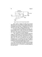
Figure 3-14. Method of repairing compressor foundations where the block has separated
from the mat.
Figure 3-14 illustrates a method of repairing separation between the
block and mat. Vertical, or near-vertical, holes are drilled through the
foundation and into the mat. These holes are usually placed in the foundation around the outer periphery of the equipment. Next, rebar is placed
in the holes along with an injection tube, and the entrance of the hole is
sealed with an epoxy material. After the seal cures, the annular space
around the rebar is pressure-filled with an epoxy liquid, and any cracks
that the holes cross are then pressure-grouted from the inside out as pressure builds. The curing of the injected epoxy completes the foundation
repair.
Grouting Skid-Mounted Equipment
A skid is a steel structure, used as a shipping platform, that is subsequently installed on a concrete pad or foundation at the job site. This
installation concept, most often called “packaging,” allows the manufacturer to factory assemble a unit under shop conditions. Packages are frequently complete with accessories, instruments and controls. The cost of
packaging is usually much less than would be required for field assembly,
particularly where the job site is in a remote part of the world.
92
Machinery Component Maintenance and Repair
Figure 3-15. A typical skid-mounted integral gas engine compressor complete with accessories, controls, and instrumentation.
When the installations are temporary, and relocation of the equipment
at a later date is anticipated, cement grouts are generally used. Because
cement grouts do not bond well to steel surfaces, lifting the skid at a later
date is relatively easy. On the other hand, when the installation is to be
permanent, epoxy grouts are generally utilized. The advantage of an epoxy
grout lies in the fact that it bonds extremely well to both concrete and
steel. Epoxy grouts also provide an oil barrier to protect the underlying
concrete foundation. Concrete exposed to lubricating oils over a long
period of time can become severely degraded and lose all its structural
properties.
A typical skid-mounted integral gas engine compressor is shown in
Figure 3-15. When proper techniques are carried out during the original
installation, the grout should contact the entire lower surfaces of all longitudinal and transverse “I” beams. Complete contact is necessary in order
to prevent vibration when the unit is placed in operation.
Figure 3-16 shows a foundation pad where a skid has been removed
leaving the cement grout intact. This photograph illustrates proper cement
grouting. Note the impression left in the grout by the lower flange of the
longitudinal and transverse “I” beams. Virtually 100 percent grout contact
was obtained on these load-bearing surfaces.
Figure 3-17 is an example of poor grout placement. Note the lack of
support in the center where most of the machinery weight is concentrated.
Long, unsupported spans are an invitation to resonant vibration problems
and to progressive sagging of the beams with age. Progressive sagging
Machinery Foundations and Grouting
93
Figure 3-16. Proper skid grouting.
Figure 3-17. Poor grout placement on a similar installation.
eventually causes continual misalignment problems. Further, the anchor
bolts on the compressor side of the crankcase are attached to one of the
internal longitudinal beams. When the equipment is at rest, there may be
perfect alignment; however, when the equipment is running, the beam may
be flexing much the same as a suspension bridge. If this is true, fatigue
of the crankshaft and bearing damage may result.
The obvious solution to this defect is to grout-in the unsupported sections. Since cement grout will not bond well to itself or concrete, any
94
Machinery Component Maintenance and Repair
regrouting should be carried out with an epoxy grout because of the inherent bonding properties of epoxies. Some epoxies will even bond to oily
surfaces.
Grouting of Oil-Degraded Concrete
In establishing guidelines for the use of epoxy materials on oilsaturated concrete, the expected results should be compared with the
properties of good concrete because these were the criteria invoked when
the installation was originally designed.
The compressive strength of good concrete will vary from 2,500 to
7,000 psi depending upon its cement content, curing conditions, etc. The
internal tensile strength should be about 8 to 10 percent of the compressive strength or 200 to 700 psi. The tensile strength at the surface of
formed concrete may be as low as 75 psi and the surface of a steeltroweled floor may be as low as 50–100 psi due to laitance on the surface.
Consequently, good surface preparation must be carried out before a satisfactory bond of epoxy to concrete can be obtained.
Experience has definitely shown that the best method of preparing a
concrete surface for bonding is through mechanical scarification to
remove surface laitance. This scarification can be accomplished by chipping away the surface, sandblasting or grinding in this order of preference.
At one time acid washing was widely respected as a means of surface
preparation, but this practice has not proved reliable. When contaminants,
such as oil or grease, are present, special consideration should be given
to surface preparation and epoxy thickness.
Although concrete can absorb oil, the process is, fortunately, relatively
slow. Once oil has been absorbed a gradual degradation in both tensile
and compressive strengths will follow and given enough time the compressive strength of the concrete may be reduced to the point where it can
be crumbled between the fingers. Preventive measures, such as sealing the
concrete with an epoxy sealer to provide a barrier, can avoid this problem.
This is usually done at the time of original construction. Remedial measures can also be used once the problem has occurred. Most of these remedial techniques involve surface preparation, patching, or transfer of
loading.
The importance of epoxy grout thickness is better understood when it
is recognized that in solid materials, forces resulting from compressive
loading are dispersed throughout the solid in a cone-shaped pattern with
the apex at the point of loading. In tensile point loading the force pattern
is such that, on failure, a hemispherically shaped crater remains. Consequently, the weaker the concrete, the thicker the epoxy covering should be
in order that loading can be sufficiently distributed before force is trans-
Machinery Foundations and Grouting
95
ferred to the concrete. For example, a severely oil degraded foundation
may be capped with a thick layer of epoxy grout in much the same manner
as a dentist caps a weak tooth. If you can contain a weak material, you
can maintain its strength.
There have been many repair jobs with epoxy grout on foundations of
reciprocating machinery where oil degradation was so severe that it was
impossible to remove all oil-soaked concrete before regrouting. In such
cases, regrouting can sometimes be done with the equipment in place.
Such repairs are accomplished by chipping away the oil grout from the
foundation shoulder and as far as one-half of the load bearing area under
the equipment. It is important that enough grout remain to support the
equipment while repairs are being conducted. The advantage of removing
some of the old grout under the equipment is to provide a structurally
sound area after repairs, equivalent to that supporting area which would
be available had the equipment originally been installed on rails or sole
plates. Once this is done, the equipment can be pressure-grouted as discussed later in this chapter. Enough concrete is removed to round off the
shoulders to a cross-sectional radius of 11/2 to 2 ft. Then vertical holes can
be drilled into the exposed concrete with a pneumatic rock drill. Usually
these holes are placed two ft (about 60 cm) apart and are drilled to a depth
to provide penetration through the remaining oil-soaked concrete and at
least two ft into the undamaged concrete below. In addition, holes can be
drilled in the remaining part of the foundation shoulders at such angles so
as to cross below the oil pan at an elevation of approximately two to three
ft below the pan or trough. Afterward, additional horizontal reinforcing
steel can be installed and wired to the vertical members which were earlier
cemented into the good concrete with an epoxy adhesive. The purpose of
the new reinforcing steel is to transfer as much load as possible to an area
where the concrete was unaffected by oil degradation.
Pressure-Injection Regrouting
Pressure-grouting is a repair process whereby equipment can be reaffixed on the foundation without lifting the equipment, without completely
chipping away the old grout, and without repositioning and complete
regrouting. Pressure grouting should not, however, be considered a
panacea. Nevertheless, when properly used it can be a valuable tool.
Shoulder Removal Method
Pressure-injection regrouting techniques offer equipment operators
important advantages of reduced downtime, lower labor costs, and less
96
Machinery Component Maintenance and Repair
Figure 3-18. Illustrating the damage done to a compressor foundation before making repairs
by pressure-injection regrouting, shoulder removal method (courtesy Adhesive Services
Company).
revenue lost from idle equipment. These techniques make possible satisfactory and long life regrouts with machine downtime at a minimum.
Figure 3-18 shows typical damage before making repairs. Figure 3-19
is the first step in conducting repairs where the old grout is chipped away
along with any damaged or oil soaked concrete. It is desirable to remove
enough old grout from beneath the machine so that a load bearing area
equivalent to a rail or sole plate mounting can be provided by the epoxy
grout once it has been poured. If the foundation itself is cracked, it should
be repaired before proceeding further. Otherwise, the effectiveness of the
regrout will not be maintained over a long period of time.
After the old grout has been chipped away, holes are drilled into the
remaining grout for the installation of injection tubes, and are usually
spaced 18 in., or approximately 45 cm, apart (see Figure 3-20). The copper
tubing installed in these holes should be sealed with epoxy putty or electrician’s putty as illustrated in Figure 3-21.
Before installing forms, all anchor bolts should be isolated to provide
at least a 1/4 in. barrier. This minimizes the possibility of later stress cracking of the grout shoulder and also allows stretching of the anchor bolt
from the bottom of the nut to the bottom of the anchor bolt sleeve when
torquing the anchor bolts. Forms should be designed to provide a grout
level of at least one in. above the machine base (see Figure 3-22). This
raised shoulder acts as an effective horizontal restraint for the machine
and thereby reduces lateral movement. Forms should be near liquid tight
to contain the epoxy grout mortar. Any holes in the forms can be plugged
Machinery Foundations and Grouting
97
Figure 3-19. The first step of repair is to remove the shoulder and about 1/2 of the loadbearing area using a pneumatic jumbo rivet buster (courtesy Adhesive Services Company).
Figure 3-20. Drilling of injection holes into the old grout using a pneumatic drill (courtesy
Adhesive Services Company).
with electrician’s putty before pouring the mortar. Forms should be waxed
with a quality paste wax before installation in order to facilitate easy
removal.
Once the forms have been poured and the grout cured for approximately
24 hours, pressure-injection regrouting is carried out to provide a liquid
98
Machinery Component Maintenance and Repair
Figure 3-21. Installing copper tubes for pressure-injection (courtesy Adhesive Services
Company).
Figure 3-22. Installing forms and repouring the shoulder with an epoxy grout (courtesy
Adhesive Services Company).
Machinery Foundations and Grouting
99
Figure 3-23. Removing forms and pressure-injecting an epoxy adhesive into the cracks and
voids under the machine base. Excess epoxy is drained into the trough under the oil pan
(courtesy Adhesive Services Company).
shim of epoxy between the remaining old grout and the equipment base
as illustrated in Figure 3-23. Once this shim of grout has cured, the
forms are removed and the foundation dressed and painted according to
Figure 3-24.
Through-the-Case Method
Occasionally, in spite of the best intentions, proper techniques are not
used and grout failure results. The cause might be air trapped under the
equipment when grouting, or foam under the equipment because of
improper grout preparation, or loss of adhesion caused by improper
surface preparation. Whatever the cause, there is movement that must be
stopped. If the grout and foundation are in good structural condition,
pressure-grouting through the case may be a practical solution to the
problem. Refer to Figure 3-25 for a good illustration of this grouting method.
With this procedure, the equipment is shut down and the oil removed
and cleaned from the crankcase. Holes are drilled through the case and
tapped to accommodate grease fittings. Usually, holes are drilled on about
100
Machinery Component Maintenance and Repair
Figure 3-24. The foundation is dressed and painted, thereby completing the repairs (courtesy Adhesive Services Company).
Figure 3-25. Method of rectifying grout installation where surface foam was present3.
two-ft centers. Alignment is then checked and corrected as necessary. A
grease fitting is installed in one of the holes near the center and pressure
grouting is begun. Dial indicator gauges should be used to confirm that
pressure grouting is being accomplished without lifting the equipment.
Pressure grouting should proceed in both directions from the center. As
soon as clear epoxy escapes from the adjacent hole, a grease fitting
is installed and injection is begun at the next location. This step-wise
Machinery Foundations and Grouting
101
procedure is continued until clear epoxy is forced from all sides of the
equipment. After curing, alignment is rechecked and the equipment
returned to service.
Pressure Grouting Sole Plates3
Occasionally when installing sole plates, a contractor will fail to clean
them properly before grouting. Later this will cause loss of adhesion and
result in excessive movement. Pressure grouting of sole plates can be
accomplished with a relatively high degree of success if proper techniques
are used. Refer to Figure 3-26 for an illustration of this procedure.
A small pilot hole is drilled through the sole plate at a 45° angle beginning about one-third of the distance from the end of the sole plate. The
hole is then counterbored. The pilot hole is reamed out and tapped to
accommodate 1/8 in. pipe. Fittings are installed and epoxy can be injected
while the equipment is running until the epoxy begins to escape around
the outer periphery of the sole plate as illustrated. Usually, oil is flushed
out from beneath the sole plate along with the epoxy. Flushing should be
continued until clear epoxy appears. It is not uncommon that flow will
channel to the extent that epoxy will escape from only 30 to 40 percent
of the sole plate circumference during the first injection. The epoxy will
Figure 3-26. Pressure grouting of sole plates3.
102
Machinery Component Maintenance and Repair
begin to gel in about 15 minutes at the operating temperature of 160° to
180°F. A second injection is carried out after sufficient gelling has been
accomplished to restrict flow to ungrouted areas. Two or three injections
at about 15-minute intervals are usually required to effect 100 percent coverage under the sole plate. Epoxy will bond through a thin lubricating oil
film at about 150 to 200 psi.
One person should be assigned for every two to three sole plates that
are loose. To the extent possible, pressure grouting of all sole plates should
proceed at the same time. Once the grouting is complete, the equipment
should be shut down for at least 6 hours to allow the epoxy to cure. Alignment should be checked and chocks machined or shimmed, if necessary,
before the equipment is returned to service.
This technique has also been used without shutting the equipment
down. However, it is somewhat less reliable under these circumstances.
Nevertheless, if for some unknown reason a sole plate comes loose after
it has been grouted, the process can be repeated. It is a simple matter to
remove the fittings, rebore and retap the hole, and thereby use the same
injection site.
Pressure grouting sole plates seldom changes alignment. We attribute
this to the fact that excess epoxy is squeezed from beneath the sole plate
by the weight of the equipment. For purposes of illustration, assume the
equipment is being aligned with the aid of jack screws having hexagonal
heads and ten threads per in. One revolution of the screw would raise or
lower the equipment 100/1000; moving the screw one face would create a
change of 1/6 this amount or 16/1000. However, one face change on a jack
screw is scarcely detectable when measuring web deflections. Nevertheless, the film thickness of epoxy under the sole plate should be far less
than 16/1000. Thus, alignment should not be changed when equipment is
pressure-grouted.
Prefilled Equipment Baseplates: How to Get a Superior Equipment
Installation for Less Money*
Why Be Concerned
Proper field installation of rotating equipment has a tremendous impact
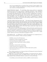
on the life-cycle cost of machinery. According to statistical reliability
analysis, as much as 65 percent of the life-cycle costs are determined
during the design, procurement, and installation phases of new machin* Contributed by Todd R. Monroe, P.E., and Kermit L. Palmer, Stay-Tru® Services, Inc.,
Houston, Texas.
Machinery Foundations and Grouting
103
ery applications5. While design and procurement are important aspects for
any application, the installation of the equipment plays a very significant
role. A superb design, poorly installed, gives poor results. A moderate
design, properly installed, gives good results5.
A proper installation involves many facets, such as good foundation
design, no pipe strain, and proper alignment, just to name a few. All of
these issues revolve around the idea of reducing dynamic vibration in the
machinery system. Great design effort and cost are expended in the construction of a machinery foundation, as can be seen in Figure 3-27. The
machinery foundation, and the relationship of F = ma, is extremely important to the reliability of rotating equipment. Forces and mass have a direct
correlation on the magnitude of vibration in rotating equipment systems.
The forces acting on the system, such as off-design operating conditions,
unbalance, misalignment, and looseness, can be transient and hard to
quantify. An easier and more conservative way to minimize motion in the
system is to utilize a large foundational mass. Through years of empirical
evidence, the rule of thumb has been developed that the foundation mass
should be three to five times the mass of the centrifugal equipment system.
Figure 3-27. Construction of machinery foundation.
104
Machinery Component Maintenance and Repair
How well the machinery system is joined to the foundation system is
the key link to a proper installation and to reduced vibration. The baseplate, or skid, of the machinery system must become a monolithic member
of the foundation system. Machinery vibration should ideally be transmitted through the baseplate to the foundation and down through the
subsoil. “Mother earth” can provide very effective damping, i.e., modification of vibration frequency and attenuation of its amplitude. Failure to
do so results in the machinery resonating on the baseplate, as shown in
Figure 3-28. Proper machinery installation results in significant increase
in mean time between failures (MTBF), longer life for mechanical seal
and bearings, and a reduction in life-cycle cost6.
The issue is to determine the most cost-effective method for joining the
equipment baseplate to the foundation. Various grouting materials and
methods have been developed over the years, but the quest always boils
down to cost: life-cycle costs versus first cost. It’s the classic conflict
between the opposing goals of reliability professionals and project personnel. Machinery engineers want to use an expensive baseplate design
with epoxy grout; project engineers want to use a less expensive baseplate
design with cementitious grout.
A new grouting method, the Stay-Tru® Pregrouted Baseplate System,
and a new installation technique, the Stay-Tru® Field Installation System,
Figure 3-28. Machinery vibration.
Machinery Foundations and Grouting
105
bridge the gap, and utilizing these two systems satisfies the requirements
of both job functions.
Conventional Grouting Methods
The traditional approach to joining the baseplate to the foundation has
been to build a liquid-tight wooden form around the perimeter of the foundation, and fill the void between the baseplate and the foundation with
either a cementitious or epoxy grout. There are two methods used with
this approach, the two-pour method, shown in Figure 3-29, and the onepour method, shown in Figure 3-30.
The two-pour method is the most widely used, and can utilize either
cementitious or epoxy grout. The wooden grout forms for the two-pour
method are easier to build because of the open top. The void between the
foundation and the bottom flange of the baseplate is filled with grout on
the first pour, and allowed to set. A second grout pour is performed to fill
the cavity of the baseplate, by using grout holes and vent holes provided
in the top of the baseplate.
The one-pour grouting method reduces labor cost, but requires a more
elaborate form-building technique. The wooden grout form now requires
a top plate that forms a liquid-tight seal against the bottom flange of the
Figure 3-29. Two-pour grout method.
106
Machinery Component Maintenance and Repair
Figure 3-30. One-pour grout method.
baseplate. The form must be vented along the top seal plate, and be sturdy
enough to withstand the hydraulic head produced by the grout. All of the
grout material is poured through the grout holes in the top of the baseplate. This pour technique requires good flow characteristics from the
grout material, and is typically used for epoxy grout applications only.
Field Installation Problems Explained
Grouting a baseplate or skid to a foundation requires careful attention
to many details. A successful grout job provides a mounting surface for
the equipment that is flat, level, very rigid, and completely bonded to the
foundation system. Many times these attributes are not obtained during
the first attempt at grouting, and expensive field-correction techniques
have to be employed. The most prominent installation problems involve
voids and distortion of the mounting surfaces.
Voids and Bonding Issues
As shown in Figure 3-31, the presence of voids at the interface between
the grout material and the bottom of the baseplate negates the very
Machinery Foundations and Grouting
107
Figure 3-31. Grout void under baseplate.
purpose of grouting. Whether the void is one inch deep, or one-thousandth
of an inch deep, the desired monolithic support system has not been
achieved. Voids prevent resonance of the foundation system and preclude
the dampening of resonance and shaft-generated vibration.
The creation of voids can be attributed to a number of possible causes:
•
•
•
•
•
Insufficient vent holes in baseplate
Insufficient static head during grout pour
Nonoptimum grout material properties
Improper surface preparation of baseplate underside
Improper surface primer
Insufficient vent holes or static head are execution issues that can be
addressed through proper installation techniques. Insufficient attention
usually leaves large voids. The most overlooked causes of voids are related
to bonding issues. These types of voids are difficult to repair because of
the small crevices to be filled.
The first issue of bonding has to do with the material properties of the
grout. Cementitious grout systems have little or no bonding capabilities.
Epoxy grout systems have very good bonding properties, typically an
average of 2,000 psi tensile adherence to steel, but surface preparation and
108
Machinery Component Maintenance and Repair
primer selection greatly affect the bond strength. The underside of the
baseplate must be cleaned, and the surface must be free of oil, grease,
moisture, and other contaminants. All of these contaminants greatly
reduce the tensile bond strength of the epoxy grout system.
The type of primer used on the underside of the baseplate also affects
the bond between the epoxy grout and the baseplate. Ideally, the best
bonding surface would be a sandblasted surface with no primer. Since this
is not feasible for conventional grouting methods, a primer must be used,
and the selection of the primer must be based on its tensile bond strength
to steel. The epoxy grout system bonds to the primer, but the primer must
bond to the steel baseplate to eliminate the formation of voids. The best
primers are epoxy based, and have minimum tensile bond strength of 1,000
psi. Other types of primers, such as inorganic zinc, have been used, but
the results vary greatly with how well the inorganic zinc has been applied.
Figure 3-32 shows the underside of a baseplate sprayed with inorganic
zinc primer. The primer has little or no strength, and can be easily removed
with the tip of a trowel. The inorganic zinc was applied too thickly, and
the top layer of the primer is little more than a powdery matrix. The ideal
dry film thickness for inorganic zinc is three mils, and is very hard to
Figure 3-32. Soft inorganic zinc primer.
Machinery Foundations and Grouting
109
achieve in practice. The dry film thickness for this example is 9 to 13 mils,
as shown in Figure 3-33.
The consequences of applying epoxy grout to such a primer are shown
in Figure 3-34, a core sample taken from a baseplate that was free of voids
for the first few days. As time progressed, a void appeared, and over the
course of a week the epoxy grout became completely “disbonded” from
the baseplate. The core sample shows that the inorganic zinc primer
bonded to the steel baseplate, and the epoxy grout bonded to the inorganic
zinc primer, but the primer delaminated. It sheared apart because it
was applied too thickly and created a void across the entire top of the
baseplate.
Distortion of Mounting Surfaces
Another field installation problem with costly implications is distortion
of the baseplate’s machined surfaces. This distortion can be either induced
prior to grouting due to poor field leveling techniques, or generated by the
grout itself.
Figure 3-33. Dry film thickness indicator.
110
Machinery Component Maintenance and Repair
Figure 3-34. Baseplate core sample with zinc primer.
Baseplate designs have become less rigid over time. Attention has been
focused on the pump end of the baseplate to provide enough structural
support to contend with nozzle load requirements. The motor end of the
baseplate is generally not as rigid, as shown in Figure 3-35. The process
of shipping, lifting, storing, and setting the baseplate can have a negative
impact on the motor mounting surfaces. Although these surfaces may have
initially been flat, there often is work to be done when the baseplate
reaches the field.
Using the system of jack bolts and anchor bolts of Figure 3-36, the
mounting surfaces can be reshaped during the leveling process, but the
Machinery Foundations and Grouting
111
Figure 3-35. Underside of American Petroleum Institute (API) baseplate.
concepts of flatness and level have become confused. Flatness cannot be
measured with a precision level, and unfortunately this has become the
practice of the day. A precision level measures slope in inches per foot,
and flatness is not a slope, it is a displacement. In the field, flatness should
be measured with either a ground straightedge or bar and a feeler gauge,
as shown in Figure 3-37, not with a level. Once the mounting surfaces are
determined to be flat, then the baseplate can be properly leveled. This confusion has caused many baseplates to be installed with the mounting surfaces out of tolerances for both flatness and level.
The other issue of mounting surface distortion comes from the grout
itself. All epoxy grout systems have a slight shrinkage factor. While this
shrinkage is very small, typically 0.0002≤/in, the tolerances for flatness
and level of the mounting surfaces are also very small. The chemical
reaction that occurs when an epoxy grout resin and hardener are
mixed together results in a volume change that is referred to as shrinkage.
112
Machinery Component Maintenance and Repair
Figure 3-36. Anchor bolt and jack bolt system.
Figure 3-37. Flatness and coplanar check.
Machinery Foundations and Grouting
113
Figure 3-38. Grout cure and mounting surface distortion.
Chemical cross-linking and volume change occur as the material cools
after the exothermic reaction. Epoxy grout systems cure from the inside
out, as shown in Figure 3-38. The areas closest to the baseplate vs. grout
interface experience the highest volume change.
Baseplates with sturdy cross-braces are not affected by the slight
volume change of the grout. For less rigid designs, the bond strength of
the epoxy grout can be stronger than the baseplate itself. Referring back
to Figure 3-38, after the grout has cured the motor mounting surfaces
become distorted and are no longer coplanar. Tolerances for alignment and
motor soft foot become very difficult to achieve in this scenario. This
“pull-down” phenomenon has been proven by finite element analysis
(FEA) modeling and empirical lab tests jointly performed by a major grout
manufacturer and an industrial grout user.
Hidden Budget Busters
Correcting the problems of voids and mounting surface distortion in the
field is a very costly venture. Repairing voids takes a lot of time, patience,
and skill to avoid further damage to the baseplate system. Field machining the mounting surfaces of a baseplate also involves commodities that
are in short supply: time and money.
The real problem with correcting baseplate field installation problems
is that the issues of “repair” are not accounted for in the construction
114
Machinery Component Maintenance and Repair
budget. Every field correction is a step backward in both time and
money. For a fixed-cost project, the contractor must absorb the cost. In a
cost-plus project, the client is faced with the cost. Either way, the parties
will have a meeting, which is just another drain on available time and
money.
Pregrouted Baseplates
The best way to solve a problem is to concentrate on the cause, rather
than developing solutions addressing the effects. The answer for resolving field installation problems is not to develop better void repair procedures or field machining techniques, it is to eliminate the causes of voids
and mounting surface distortion.
A new baseplate grouting system has been developed to address the
causes of field installation problems. The term pregrouted baseplate
sounds simple enough, but addressing the causes of installation problems
involves far more than flipping a baseplate over and filling it up with grout.
In that scenario, the issues of surface preparation, bonding, and mounting
surface distortion still have not been addressed. A proper pregrouted baseplate provides complete bonding to the baseplate underside, contains zero
voids, and provides mounting surfaces that are flat, coplanar, and colinear within the required tolerances. To assure that these requirements are
met, a good pregrout system will include the following.
Proper Surface Preparation
Baseplates that have been specified with an epoxy primer on the underside should be solvent washed, lightly sanded to remove the grossly finish,
and solvent washed again. For inorganic zinc and other primer systems,
the bond strength to the metal should be determined. There are several
methods for determining this, but as a rule of thumb, if the primer can be
removed with a putty knife, the primer should be removed. Sandblasting
to an SP-6 finish is the preferred method for primer removal. After sandblasting, the surface should be solvent washed, and grouted within 8 hours.
Void-free Grout Installation
By its very nature, pregrouting a baseplate greatly reduces the problems
of entrained air creating voids. However, because grout materials are
highly viscous, proper placement of the grout is still important to prevent