Machinery Components Maintenance And Repair Episode 2 Part 1 pps
Bạn đang xem bản rút gọn của tài liệu. Xem và tải ngay bản đầy đủ của tài liệu tại đây (342.95 KB, 25 trang )
origin and philosophy behind these tests and their purpose were explained.
Here are the actual test procedures:
U
mar
(or Traverse) Test
1. Perform the mechanical adjustment, calibration and/or setting of the
machine for the particular proving rotor being used for the test,
ensuring that the unbalance in the rotor is smaller than five times the
claimed minimum achievable residual unbalance for the machine.
2. Put 10 to 20 times the claimed minimum achievable residual unbal-
ance on the rotor by adding two unbalance masses (such as balanc-
ing clay). These masses shall not be:
•
in the same transverse plane
•
in a test plane
•
at the same angle
•
displaced by 180°
3. Balance the rotor, following the standard procedure for the machine,
by applying corrections in two planes other than test planes or those
used for the unbalance masses in a maximum of four runs at the
balancing speed selected for the U
mar
Test.
4. In the case of horizontal machines, after performing the actions
described in 1 to 3, change the angular reference system of the
machine by 60 or 90°, e.g., turn the end-drive shaft with respect to
the rotor, turn black and white markings, etc.
5. For horizontal or vertical two-plane machines, attach in each of the
two prepared test planes a test mass equal to ten times the claimed
minimum achievable residual unbalance.
For example, if the ISO proving rotor No. 5 weighing 110 lbs
(50,000 g) is used, the weight of each test mass is calculated as
follows:
The claimed minimum achievable residual specific unbalance is, say
The claimed minimum achievable residual unbalance per test plane,
i.e., for half the rotor weight, is therefore:
1
50 000
20
0 000020
05
U per plane
g
in
gin
mar
()
=◊
=◊
,
1 0 000020ein
mar
=
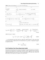
Balancing of Machinery Components 315
The desired 10 U
mar
test mass per plane is therefore equivalent to:
If the test mass is attached so that its center of gravity is at a radius
of four in. (effective test mass radius), the actual weight of each test
mass will be:
When two of these test masses are attached to the rotor (one in each
test plane as shown in Figure 6-30), they create a combined static
unbalance in the entire rotor of 10 U
mar
(or specific unbalance of 10
e
mar
), since each test mass had been calculated for only one half of
the rotor weight.
Note 1: If a proving rotor with asymmetric CG and/or test planes
is used, the test masses should be apportioned between the two test
planes in such a way that an essentially parallel displacement of the
principal inertia axis from the shaft axis results.
Note 2: U
mar
Tests are usually run on inboard rotors only. However,
if special requirements exist for balancing outboard rotors, a U
mar
Test may be advisable which simulates those requirements.
6. Attach the test masses in phase with one another in all 12 equally
spaced holes in the test planes, using an arbitrary sequence. Record
amount-of-unbalance readings in each plane for each position of the
masses in a log shown in Figure 6-31. For the older style 8-hole
rotors, a log with 45° test mass spacing must be used.
m
gin
in
g=
◊
=
5
4
125
.
.
.
10
10 0 5
05
U per plane
gin
gin
mar
()
=◊ ◊
=◊
316 Machinery Component Maintenance and Repair
Figure 6-30. Proving rotor with test masses for “Umar” test.
7. Plot the logged results as shown in Figure 6-32 in two diagrams, one
for the left and one for the right plane (or upper and lower planes on
vertical machines). For 8-hole rotors, use a diagram with 45°
spacing.
Connect the points in each diagram by an averaging curve. It
should be of sinusoidal shape and include all test points.
If the rotor has been balanced (as in 3) to less than
1
/
2
U
mar
, the
plotted test readings may scatter closely around the 10 U
mar
line and
not produce a sinusoidal averaging curve. In that case add
1
/
2
U
mar
residual unbalance to the appropriate test plane and repeat the test.
Draw a horizontal line representing the arithmetic mean of the scale
reading into each diagram and add two further lines representing
±12 percent of the arithmetic mean for each curve, which accounts
for 1 U
mar
plus 20 percent for the effects of variation in the position
of the masses and scatter of the test data.
Balancing of Machinery Components 317
Figure 6-31. Log for “Umar” test.
Figure 6-32. Diagram showing residual unbalance.
If all the plotted points are within the range given by those two
latter lines for each curve, the claimed minimum achievable resid-
ual unbalance has been reached.
If the amount-of-unbalance indication is unstable, read and plot
the maximum and minimum values for all angular positions of the
test mass. Again, all points must be within the range given.
Note: If different U
mar
values are specified for different speeds, the
test should be repeated for each.
8. On horizontal and vertical single-plane balancing machines designed
to indicate static unbalance only, proceed in the same way as
described in 1 and 7 but use only one test mass in the left (or lower)
plane of the proving rotor. This test mass must be calculated using
the total weight of the proving rotor.
9. On vertical machines, the spindle balance should be checked.
Remove the proving rotor and run the machine. The amount of unbal-
ance now indicated should be less than the claimed minimum achiev-
able residual unbalance.
Unbalance Reduction Test
This test is intended to check the combined accuracy of amount-of-
unbalance indication, angle indication, and plane separation. Experience
gained with running the test in accordance with the procedure described
in ISO 2953 (1973 version) showed that the operator could influence the
test results because he knew in advance what the next reading should be.
For instance, if a reading fluctuated somewhat, he could wait until the indi-
cator showed the desired value and at that moment actuate the readout
retention switch.
To avoid such operator influence, a somewhat modified procedure has
been developed similar to that used in ARP 587 (see Appendix 6C). In the
new procedure (ISO 2953—second edition) a stationary mass is attached
to the rotor in the same plane in which the test mass is traversed. The
unbalance resulting from the combination of two test masses, whose
angular relationship changes with every run, is nearly impossible to
predict.
To have a simultaneous check on plane separation capability of the
machine, a stationary and a traversing (or “traveling”) test mass are also
attached in the other plane. Readings are taken in both planes during each run.
Unbalance readings for successive runs are logged on the upper “log”
portion of a test sheet, and subsequently plotted on the lower portion con-
taining a series of URR limit circles. All plotted points except one per
plane must fall within their respective URR limit circles to have the
318 Machinery Component Maintenance and Repair
machine pass the test. A similar procedure has been used by the SAE
for more than ten years and has proven itself to be practical and
foolproof.
The new Unbalance Reduction Test is divided into an inboard and an
outboard test. The inboard test should be conducted for all machines; in
addition, the outboard test should be conducted for all horizontal two-
plane machines on which outboard rotors are to be balanced.
Each test consists of two sets of 11 runs, called “low level” and “high
level” tests. When using the older style proving rotor with eight holes per
plane, only seven runs are possible. The low level tests are run with a set
of small test masses, the high level tests with a larger set to test the
machine at different levels of unbalance. Test mass requirements and
procedures are described in detail in Figure 6-33.
Balance Tolerances
Every manufacturer and maintenance person who balances part of his
product, be it textile spindles or paper machinery rolls, electric motors or
gas turbines, satellites or re-entry vehicles, is interested in a better way to
determine an economical yet adequate balance tolerance. As a result,
much effort has been spent by individual manufacturers to find the solu-
tion to their specific problem, but rarely have their research data and con-
clusions been made available to others.
In the 1950s, a small group of experts, active in the balancing field,
started to discuss the problem. A little later they joined the Technical Com-
mittee 108 on Shock and Vibration of the International Standards Orga-
nization and became Working Group 6, later changed to Subcommittee
1 on Balancing and Balancing Machines (ISO TC-108/Sc1). Interested
people from other countries joined, so that the international group now
has representatives from most major industrialized nations. National meet-
ings are held in member countries under the auspices of national standards
organizations, with balancing machine users, manufacturers and others
interested in the field of dynamic balancing participating. The national
committees then elect a delegation to represent them at the annual inter-
national meeting.
One of the first tasks undertaken by the committee was an evaluation
of data collected from all over the world on required balance tolerances
for millions of rotors. Several years of study resulted in an ISO Standard
No. 1940 on “Balance Quality of Rotating Rigid Bodies” which, in the
meantime, has also been adopted as S2.19-1975 by the American National
Standards Institute (“ANSI,” formerly USASI and ASA). The principal
points of this standard are summarized below. Balance tolerance
Balancing of Machinery Components 319
320 Machinery Component Maintenance and Repair
Figure 6-33. Maximum permissible residual specific unbalance corresponding to various
balancing quality grades “G,” in accordance with ISO 1940.
nomograms, developed by the staff of Schenck Trebel Corporation from
the composite ISO metric table, have been added to provide a simple-to-
use guide for ascertaining recommended balance tolerances (see Figures
6-34 and 6-35).
Balance Quality Grades
We have already explained the detrimental effects of unbalance and the
purpose of balancing. Neither balancing cost considerations, nor various
rotor limitations such as journal concentricity, bearing clearances or fit,
thermal stability, etc., permit balancing every rotor to as near zero unbal-
ance as might theoretically be thought possible. A tolerance must be set
to allow a certain amount of residual unbalance, just as tolerances are set
for various other machine shop operations. The question usually is, how
much residual unbalance can be permitted while still holding detrimental
effects to an insignificant or acceptable level?
The recommendations given in ISO 1940 will usually produce satis-
factory results. The heart of the Standard is a listing of various rotor types,
grouped according to “quality grades” (see Table 6-5). Anyone trying to
determine a reasonable balance tolerance can locate his rotor type in the
table and next to it find the assigned quality grade number. Then the graph
in Figure 6-33 or the nomograms in Figures 6-34 and 6-35 are used to
establish the gram ·inch value of the applicable balance tolerance (i.e.,
“permissible residual unbalance” or U
per
).
Except for the upper or lower extremes of the graph in Figure 6-33,
every grade incorporates 4 bands. For lack of a better delineation, the
bands might be considered (from top to bottom in each grade) substan-
dard, fair, good, and precision. Thus, the graph permits some adjustment
to individual circumstances within each grade, whereas the nomograms
list only the median values (centerline in each grade). The difference in
permissible residual unbalance between the bottom and top edge of each
grade is a factor of 2.5. For particularly critical applications it is, of course,
also possible to select the next better grade.
CAUTION: The tolerances recommended here apply only to rigid
rotors. Recommendations for flexible rotor tolerances are contained in
ISO 5343 (see Appendix 6C) or in Reference 2.
Special Conditions to Achieve Quality Grades G1 and G0.4
To balance rotors falling into Grades 1 or 0.4 usually requires that the
following special conditions be met:
Balancing of Machinery Components 321
322 Machinery Component Maintenance and Repair
Figure 6-34. Balance tolerance nomogram for G-2.5 and G-6.3, small rotors.
Balancing of Machinery Components 323
Figure 6-35. Balance tolerance nomogram for G-2.5 and G-6.3, large rotors.
Table 6-5
Balance Quality Grades for Various Groups of Representative
Rigid Rotors in Accordance with ISO 1940 and ANSI S2.19-1 975
Balance
Quality
Grade G Rotor Types—General Examples
G 4000 Crankshaft-drives (2) of rigidly mounted slow marine diesel engines with
uneven number of cylinders (3).
G 1600 Crankshaft-drives of rigidly mounted large two-cycle engines.
G 630 Crankshaft-drives of rigidly mounted large four-cycle engines. Crankshaft-
drives of elastically mounted marine diesel engines.
G 250 Crankshaft-drives of rigidly mounted fast four-cylinder diesel engines (3).
G 100 Crankshaft-drives of fast diesel engines with six and more cylinders (3).
Complete engines (gasoline or diesel) for cars, trucks and locomotives (4).
G 40 Car wheel (5), wheel rims, wheel sets, drive shafts. Crankshaft-drives of
elastically mounted fast four-cycle engines (gasoline or diesel) with six
and more cylinders (3). Crankshaft-drives for engines of cars, trucks and
locomotives.
C 16 Drive shafts (propeller shafts, cardan shafts) with special requirements.
Parts of crushing machinery. Parts of agricultural machinery. Individual
components of engines (gasoline or diesel) for cars, trucks and
locomotives. Crank-shaft-drives of engines with six or more cylinders
under special requirements.
G 6.3 Parts of process plant machines. Marine main turbine gears (merchant
service). Centrifuge drums. Fans. Assembled aircraft gas turbine rotors.
Flywheels. Pump impellers. Machine-tool and general machinery parts.
Medium and large electric armatures (of electric motors having at least
80 mm shaft height) without special requirements. Small electric
armatures, often mass produced, in vibration insensitive applications and/
or with vibration damping mountings. Individual components of engines
under special requirements.
G 2.5 Gas and steam turbines, including marine main turbines (merchant service).
Rigid turbogenerator rotors. Rotors. Turbo-compressors. Machine-tool
drives. Medium and large electrical armatures with special requirements.
Small electric armatures not qualifying for one or both of the conditions
stated in G6.3 for such. Turbine-driven pumps.
G 1 Tape recorder and phonograph drives. Grinding-machine drives. Small
electrical armatures with special requirements.
G 0.4 Spindles, discs, and armatures of precision grinders. Gyroscopes.
NOTES:
1. The quality grade number represents the maximum permissible circular velocity of the
center of gravity in mm/sec.
2. A crankshaft drive is an assembly which includes the crankshaft, a flywheel, clutch,
pulley, vibration damper, rotating portion of connecting rod, etc.
3. For the purposes of this recommendation, slow diesel engines arc those with a piston
velocity of less than 30 ft. per sec., fast diesel engines are those with a piston velocity
of greater than 30 ft per sec.
4. In complete engines, the rotor mass comprises the sum of all masses belonging to the
crankshaft-drive.
5. G 16 is advisable for off-the-car balancing due to clearance or runout in central pilots
or bolt hole circles.
For Quality Grade 1:
•
Rotor mounted in its own service bearings
•
No end-drive
For Quality Grade 0.4:
•
Rotor mounted in its own housing and bearings
•
Rotor running under service conditions (bearing preload, tempera-
ture)
•
Self-drive
Only the highest quality balancing equipment is suitable for this work.
Applying Tolerances to Single-Plane Rotors
A single-plane rotor is generally disc-shaped and, therefore, has only a
single correction plane. This may indeed be sufficient if the distance
between bearings is large in comparison to the width of the disc, and pro-
vided the disc has little axial runout. The entire tolerance determined from
such graphs as shown in Figures 6-34 and 6-35 may be allowed for the
single plane.
To verify that single-plane correction is satisfactory, a representative
number of rotors that have been corrected in a single plane should be
checked for residual couple unbalance. One component of the largest
residual couple (referred to the two-bearing planes) should not be larger
than one half the total rotor tolerance. If it is larger, moving the correc-
tion plane to the other side of the disc (or to some optimal location
between the disc faces) may help. If it does not, a second correction
plane will have to be provided and a two-plane balancing operation
performed.
Applying Tolerances to Two-Plane Rotors
In general, one half of the permissible residual unbalance is applied to
each of the two correction planes, provided the distance between (inboard)
rotor CG and either bearing is not less than
1
/
3
of the total bearing distance,
and provided the correction planes are approximately equidistant from the
CG, having a ratio no greater than 3 : 2.
If this ratio is exceeded, the total permissible residual unbalance (U
per
)
should be apportioned to the ratio of the plane distances to the CG. In
other words, the larger portion of the tolerance is allotted to the correc-
Balancing of Machinery Components 325
tion plane closest to the CG; however, the ratio of the two tolerance por-
tions should never exceed 7 :3, even though the plane distance ratio may
be higher.
For rotors with correction plane distance (b) larger than the bearing span
(d), the total tolerance should be reduced by the factor d/b before any
apportioning takes place.
For rotors with correction plane distance smaller than
1
/
3
of the bearing
span and for rotors with two correction planes outboard of one bearing, it
is often advisable to measure unbalance and state the tolerance in terms
of (quasi-) static and couple unbalance. Satisfactory results can generally
be expected if the static residual unbalance is held within the limits of
and the couple residual unbalance within
(where d = bearing span)
If separate indication of static and couple unbalance is not desired or
possible, the distribution of the permissible residual unbalance must be
specially investigated, taking into account, for instance, the permissible
bearing loads
4
. It may also be necessary to state a family of tolerances,
depending on the angular relationship between the residual unbalances in
the two correction planes.
For all rotors with narrowly spaced (inboard or outboard) correction
planes, the following balancing procedure may prove advantageous if U
per
is specified in terms of residual unbalance per correction plane.
1. Calibrate respectively the balancing machine to indicate unbalance
in the two chosen correction planes I and II (see Figure 6-36).
2. Measure and correct unbalance in plane I only.
3. Recalibrate or set the balancing machine to indicate unbalance near
bearing plane A and in plane II.
4. Measure and correct unbalance in plane II only.
5. Check residual unbalance with machine calibrated or set as in 3.
Allow residual unbalance portions for the inboard rotor as discussed
above (inversely proportional to the correction plane distances from
the CG), considering A and II as the correction planes; for the out-
board rotor allow no more than 70 percent of U
per
in plane II, and no
less than 30 percent in plane A.
U
U
d
couple
per
£◊
3
UU
static per
£ 3
326 Machinery Component Maintenance and Repair
Balancing of Machinery Components 327
Experimental Determination of Tolerances
For reasons of rotor type, economy, service life, environment or others,
the recommended tolerances may not apply. A suitable tolerance may then
be determined by experimental methods. For instance, a sample rotor is
balanced to the smallest achievable residual unbalance. Test masses of
increasing magnitude are then successively applied, with the rotor under-
going a test run under service conditions before each test mass is applied.
The procedure is repeated until the test mass has a noticeable influence
on the vibration, noise level, or performance of the machine. In the case
of a two-plane rotor, the effects of applying test masses as static or couple
unbalance must also be investigated. From the observations made, a per-
missible residual unbalance can then be specified, making sure it allows
for differences between rotors of the same type, and for changes that may
come about during sustained service.
Applying Tolerances to Rotor Assembly Components
If individual components of a rotor assembly are to be pre-balanced (on
arbors for instance), the tolerance for the entire assembly is usually dis-
tributed among the components on the basis of the weight that each com-
ponent contributes to the total assembly weight. However, allowance must
be made for additional unbalance being caused by fit tolerances and
mounting surface runouts. To take all these into account, an error analy-
sis should be made.
Testing a Rotor for Tolerance Compliance
If the characteristics of the available balancing equipment do not permit
an unbalance equivalent to the specified balance tolerance to be measured
Figure 6-36. Inboard and outboard rotors with narrowly spaced correction planes.
328 Machinery Component Maintenance and Repair
with sufficient accuracy (ideally within ± 10 percent of value), the U
mar
test described earlier may be used to determine whether the specified
tolerance has been reached. The test should be carried out separately for
each correction plane, and a test mass equivalent to 10 times the tolerance
should be used for each plane.
Balance Errors Due to Drive Elements
During balancing in general, and during the check on tolerance com-
pliance in particular, significant errors can be caused by the driving ele-
ments (for example, driving adapter and universal-joint drive shaft).
In Figure 6-37 seven sources of balance errors are illustrated:
1. Unbalance from universal-joint shaft.
2. Unbalance-like effect from excessive looseness or tightness in uni-
versal joints.
3. Loose fit of adapter in universal-joint flange.
4. Offset between adapter pilot (on left) and adapter bore (on right).
5. Unbalance of adapter.
6. Loose fit of adapter on rotor shaft.
7. Eccentricity of shaft extension (on which adapter is mounted) in
reference to journals.
Figure 6-37. Error sources in end-drive elements.
The effects of errors 1, 3, 4, and 5 may be demonstrated by indexing
the rotor against the adapter. These errors can then be jointly compensated
by an alternating index-balancing procedure described below. Error 2 will
generally cause reading fluctuation in case of excessive tightness, nonre-
peating readings in case of excessive looseness. Error 6 may be handled
like 1, 3, 4, and 5 if the looseness is eliminated by a set screw (or similar)
in the same direction after each indexing and retightening cycle. If not, it
will cause nonrepeating readings. Error 7 will not be discovered until the
rotor is checked without the end-drive adapter, presumably under service
conditions with field balancing equipment. The only (partial) remedy is to
reduce the runout in the shaft extension and the weight of the end-drive
elements to a minimum.
Balance errors from belt-drive pulleys attached to the rotor are consid-
erably fewer in number than those caused by end-drive adapters. Only the
pulley unbalance, its fit on the shaft, and the shaft runout at the pulley
mounting surface must be considered. Such errors are avoided altogether
if the belt runs directly over the part. Certain belt-drive criteria should be
followed.
Air- and self-drive generally introduce minimal errors if the cautionary
notes mentioned previously are observed.
Balance Errors Due to Rotor Support Elements
Various methods of supporting a rotor in a balancing machine may
cause balance errors unless certain precautions are taken. For instance,
when supporting a rotor journal on roller carriages, the roller diameter
should differ from the journal diameter by at least 10 percent, and the
roller speed should never differ less than 60 rpm from the journal speed.
If this margin is not maintained, unbalance indication becomes erratic.
A rotor with mounted rolling element bearings should be supported in
V-roller carriages (see Nomenclature, Appendix 6B). Their inclined rollers
permit the bearing outer races to align themselves to the inner races and
shaft axis, letting the rolling elements run in their normal tracks.
Rotors with rolling element bearings may also be supported in sleeve
or saddle bearings; however, the carriages or carriage suspension systems
must then have “vertical axis freedom” (see Terminology, Appendix 6A).
Without this feature, the machine’s plane separation capability will be
severely impaired because the support bridges (being connected via the
rotor) can only move in unison toward the front and rear of the machine;
thus only static unbalance will be measured.
Vertical axis freedom is also required when the support bridges or car-
riages are connected by tiebars, cradles, or stators. Only then can couple
Balancing of Machinery Components 329
unbalance be measured without misaligning the bearings in each (out-of-
phase) back-and-forth movement of the support bridges. This also holds
true for hard-bearing machines, even though bridge movement is micro-
scopically small.
Index-Balancing Procedure
A procedure of repetitively balancing and indexing (by 180°) one com-
ponent against another leads to diminishing residual unbalance in both,
until eventually one component can be indexed against the other without
a significant change in residual unbalance. Index-balancing may be used
to eliminate the unbalance errors in an end-drive adapter, for biasing an
arbor or for improving the residual unbalance in a rotor mounted on
an arbor.
If the procedure is used for a single-plane application (e.g., an end-drive
adapter), one half of the residual unbalance (after the first indexing) is
corrected in the adapter, the other half in the rotor. The cycle may have to
be repeated once or twice until a satisfactory residual unbalance is
reached.
Care should be taken that after each indexing step, set screws are tight-
ened with the same torque and in the same sequence. The procedure does
not work well unless the position of the indexed component is precisely
repeatable.
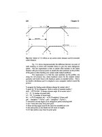
If the above iterative process becomes too tedious, a graphic solution
may be used. It is described below for a two-plane rotor mounted on an
arbor, with Figure 6-38 showing a typical plot for one plane.
1. Balance arbor by itself to minimum achievable residual unbalance.
2. Mount rotor on arbor, observing prior cautionary notes concerning
keyways, set screws, and fits.
3. Take unbalance readings for both planes and plot points P on sepa-
rate graphs for each plane. (Only one plot for one plane is shown in
Figure 6-38. The reading for this, say the left plane, is assumed to
be 35 units at an angular position of 60°.)
4. Index rotor on arbor by 180°.
5. Take unbalance readings for both planes and plot them as points P¢.
(Reading for left plane assumed to be 31 units at an angle of 225°.)
6. Find midpoint R on line connecting points P and P¢.
7. Draw line SS¢ parallel to PP¢ and passing through O.
8. Determine angle of OS (52° for left plane) and distance RP (32.5
units for left plane). Add correction mass of 32.5 units at 52° to rotor
in left correction plane.
330 Machinery Component Maintenance and Repair
Balancing of Machinery Components 331
9. Steps 6–8 must also be performed for the right plane. The rotor is
now balanced and the residual unbalance (OR in Figure 6-38)
remaining in the arbor/rotor assembly is due to arbor unbalance and
run-out. If this residual unbalance is corrected by adding a correc-
tion mass to the arbor equal hut opposite to OR, the arbor is cor-
rected and biased for subsequent rotors of the same weight and
configuration.
Additional indexing and unbalance measurement may uncover a much
reduced residual unbalance, which can again be plotted and pursued
through steps 4–9. This will probably refine both the balance of the rotor
and the bias of the arbor. If additional indexing produces inconsistent data,
the minimum level of repeatability in locating the rotor on the arbor has
been reached. Further improvement in rotor balance is not possible with
this arbor.
Recommended Margins Between Balance and Inspection Tolerances
Quite often the residual unbalance changes (or appears to have done so)
between the time when:
1. The rotor was balanced originally.
2. It is checked for balance by an inspector.
Figure 6.38. 180° indexing plot.
The following factors may contribute to these changes:
•
Calibration differences between balancing and inspection machines
•
Tooling and/or drive errors
•
Bearing or journal changes
•
Environmental differences (heat, humidity)
•
Shipping or handling damage
•
Aging or stress relieving of components
To provide a margin of safety for such changes, it is recommended that
the tolerance allowed the balancing machine operator be set below, and
the tolerance allowed at time of inspection be set above the values given
in graphs such as Figures 6-33 and 6-34. Percentages for these margins
vary between quality grades as shown in Table 6-6.
Computer-Aided Balancing
In recent years, the practice of balancing has entered into a new stage:
computerization. While analog computers have been in use on hard-
bearing machines ever since such machines came on the market, it is the
application of digital computers to balancing that is relatively new. At first,
desk top digital computers were used in large, high-speed balancing and
overspeed spin test facilities for multi-plane balancing of flexible rotors.
As computer hardware prices dropped, their application to more common
balancing tasks became feasible. The constant demand by industry for a
simpler balancing operation performed under precisely controlled condi-
tions with complete documentation led to the marriage of the small,
dedicated, table-top computer to the hard-bearing balancing machine as
332 Machinery Component Maintenance and Repair
Table 6-6
Recommended Margins Between Balance and
Inspection Tolerances
Adjustment to Recommended Tolerances
Quality Grade For Balancing For Inspection
G4000-G40 -10 percent +10 percent
G16-G2.5 -15 percent +15 percent
G1 -20 percent +20 percent
G0.4 -30 percent +30 percent
shown in Figure 6-39. And a happy marriage it is indeed, because it proved
cost effective right away in many production applications.
Features
The advantages that a computerized balancing system provides versus
the customary manual system are the many standard and not-so-standard
functions a computer performs and records with the greatest of ease and
speed. Here is a list of basic program features and optional subroutines:
•
Simplification of setup and operation
•
Reduction of operator errors through programmed procedures with
prompting
Balancing of Machinery Components 333
Figure 6-39. Hard-bearing balancing machine controlled by a combination of desk top com-
puter and vectometer instrumentation.
•
More precise definition of required unbalance corrections in terms of
different practical correction units
•
Direct indication of unbalance in drill depth for selectable drill diam-
eters and materials
•
Averaging of ten successive readings for increased accuracy
•
Automatic storage of readings taken in several runs with subsequent
calculation of the mean reading (used to average the effect of blade
scatter on turbine rotors with loose blades)
•
Readout in any desired components (in certain workpieces, polar
correction at an exact angular location is not possible. Instead,
correction may only be applied at specific intervals, e.g., 30°, 45°,
90°, etc. The computer then calculates the exact correction mass to
be applied at two adjacent components for any desired angle between
components)
•
Optimized distribution of fixed-weight correction masses to available
locations
•
Automatic comparison of initial unbalance with maximum permissi-
ble correction, and machine shutdown if the initial unbalance is too
large
•
Automatic comparison of residual unbalance with predetermined
tolerances or with angle-dependent family of tolerances
•
Translation of unbalance readings from one plane to another without
requiring a new run (for crankshafts, for instance, where correc-
tion may only be possible at certain angular locations in certain
planes)
•
Permanent record of the balancing operation, including initial and
residual unbalance, rotor identification, etc. (for quality control)
•
Machine operation as a sorter
•
Statistical analysis of unbalance
•
Connection to an X-Y plotter for graphic display of unbalance
•
Operator identification
•
Inspector identification
•
Monitoring of the number of runs and correction steps
•
Time and/or date record
Prompting Guides, Storage, and Retrieval
Prompting displays on a computer screen guide the operator every step
of the way through the program (Figure 6-40). Rotor data are stored elec-
tronically and can be recalled at a later date for balancing the same type
of rotor. Thus ABC, R1, and R2 rotor dimensions need to be entered into
the computer only once.
334 Machinery Component Maintenance and Repair
Multiple Machine Control and Programs
Different computers may be used depending on the application. They
may be mounted in the balancing machine’s instrumentation console, or
in a central electronic data processing room. A computer may control one
balancing machine, or a series of machines.
Basic computer programs are available for single and two plane bal-
ancing, field balancing, and flexible rotor balancing. Software libraries for
optional subroutines are continually growing.
Of course, the user may modify the available programs to his particu-
lar requirements, write his own programs, or have them written for him.
Thus, the potential applications of the computerized hard-bearing balanc-
ing machines are unlimited.
Balancing of Machinery Components 335
Figure 6-40. Printout of unbalance data.
Field Balancing Overview
Once a balanced rotor has been mounted in its housing and installed in
the field, it will not necessarily stay in balance forever. Corrosion, tem-
perature changes, build-up of process material and other factors may cause
it to go out of balance again and, thus, start to vibrate. However, unbal-
ance is not the only reason for vibration. Bearing wear, belt problems, mis-
alignment, and a host of other detrimental conditions will also cause it.
In fact, experience has shown that vibration is an important indication
of a machine’s mechanical condition. During normal operation, properly
functioning fans, blowers, motors, pumps, compressors, etc., emit a spe-
cific vibration signal, or “signature.” If the signature changes, something
is wrong.
Excessive vibration has a destructive effect on piping, tanks, walls,
foundations, and other structures near the vibrating equipment. Operating
personnel may be influenced too. High noise levels from vibration may
exceed legal limitations and cause permanent hearing damage. Workers
may also experience loss of balance, blurred vision, fatigue, and other dis-
comfort when exposed to excessive vibration.
Methods of vibration detection, analysis, diagnostics, and prognosis
have been described by the authors previously in detail
5
. A quick review
of the hardware required to perform field balancing should therefore
suffice.
Field Balancing Equipment
Many types of vibration indicators and measuring devices are available
for field balancing. Although these devices are sometimes called “portable
balancing machines,” they never provide direct readout of amount and
location of unbalance.
Basically, field balancing equipment consists of a combination of a suit-
able transducer and meter which provides an indication proportional to
the vibration magnitude. The vibration magnitude indicated may be dis-
placement, velocity, or acceleration, depending on the type of transducer
and readout system used. The transducer can be held by an operator, or
attached to the machine housing by a magnet or clamp, or permanently
mounted. A probe thus held against the vibrating machine is presumed to
cause the transducer output to be proportional to the vibration of the
machine.
At frequencies below approximately 15 cps, it is almost impossible to
hold the transducer sufficiently still by hand to give stable readings. Fre-
quently, the results obtained depend upon the technique of the operator;
336 Machinery Component Maintenance and Repair
this can be shown by obtaining measurements of vibration magnitude on
a machine with the transducer held with varying degrees of firmness.
Transducers of this type have internal seismic mountings and should not
be used where the frequency of the vibration being measured is less than
three times the natural frequency of the transducer.
A transducer responds to all vibration to which it is subjected, within the
useful frequency range of the transducer and associated instruments. The
vibration detected on a machine may come through the floor from adjacent
machines, may be caused by reciprocating forces or torques inherent in
normal operation of the machine, or may be due to unbalances in different
shafts or rotors in the machine. A simple vibration indicator cannot
discriminate between the various vibrations unless the magnitude at one
frequency is considerably greater than the magnitude at other frequencies.
The approximate location of unbalance may be determined by measur-
ing the phase of the vibration; for instance, with a stroboscopic lamp that
flashes each time the output of an electrical transducer changes polarity
in a given direction. Phase also may be determined by use of a phase meter
or by use of a wattmeter. Vibration measurements in one end of a machine
are usually affected by unbalance vibration from the other end. To deter-
mine more accurately the size and phase angle of a needed correction mass
in a given (accessible) rotor plane, three runs are required. One is the “as
is” condition, the second with a test mass in one plane, the third with a
test mass in the other correction plane. All data are entered into a hand-
held computer and, with a few calculation steps, transformed into amount
and phase angle of the necessary correction masses with two selected
planes. To simplify the calculation process even further, software has
recently become available which greatly facilitates single plane or multi-
plane field balancing.
Field Balancing Examples
As we saw, two methods are available for the systematic balancing of
rotors:
•
Balancing on a balancing machine
•
Field balancing in the assembled state
Both methods have specific fields of application. The balancing
machine is the correct answer from the technical and economic point of
view for balancing problems in production. Field balancing, on the other
hand, provides a practical method for the balancing of completely assem-
bled machines during test running, assembly, and maintenance.
Balancing of Machinery Components 337
It is the purpose of this section to illustrate the possibilities of field bal-
ancing on the basis of three typical balancing problems. The machines
chosen for these problems represent examples only and could at any time
be exchanged for machines with similar rotor systems. The solutions to
the problems indicated, therefore, apply equally to other machines and
types of rotor not specifically mentioned here. The following classifica-
tion will simplify the allocation of different types of machines to the three
problem solutions:
1st Problem Solution: Machines with narrow disc-shaped rotors such as
blowers, fans, grinding wheels, belt pulleys, flywheels, couplings, chucks,
gear wheels, impellers, atomizer discs, etc.
2nd Problem Solution: Machines with long roll-shaped rotors such as
centrifuges, paper rolls, electric motors and generators, beater shafts,
machine tool spindles, grinding rolls, internal combustion engines, etc.
3rd Problem Solution: Machines having multiple bearing coupled rotors
such as standing machines, twisting machines, motor generator sets, turbo
generators, cardan shafts, etc.
Field balancing of very low speed rotating assemblies (cooling tower
fans, etc.) may require special techniques which are not covered here.
The reader should discuss special requirements with the machinery
manufacturer.
First Problem: Unbalance Vibration in Blowers
Build-up on blades, corrosion, wear, and thermal loading regularly lead
to unbalance in blowers. The presence of such unbalance shows itself
externally in the form of mechanical vibration generated by the blower
rotor and transmitted via the bearings and the frame into the foundations
and finally into the environment. If the danger of this unbalance vibration
is not recognized, after a very short operating period costly damage may
be caused. This may frequently result in the destruction of the bearings,
cracks in the bearing housing and in the air channels, damage to the foun-
dation, and cracks in the building.
Solution: Field Balancing in One Plane
For economic reasons rebalancing of a blower should always be carried
out in the assembled state. This does away with the need to disassemble
338 Machinery Component Maintenance and Repair
the whole plant, to make available a balancing machine and to transport
the blower rotor to the balancing machine. Only the electronic balancing
instrument needs to be brought to where the blower is installed. The oper-
ation of the instrument and the determination of the masses required to
correct the unbalance is carried out by trained personnel. Not only does
this result in considerable cost savings but the method also provides a sig-
nificant saving in time compared to rebalancing on a balancing machine.
With careful preparation, field balancing of a blower need not take more
than 30–60 minutes.
It has been shown in practice that in over 95 percent of all blowers field
balancing in one plane is sufficient to reduce unbalance vibrations to per-
missible and safe values. The method is as follows:
1. The balancing instrument is used to measure the unbalance vibra-
tion at the bearing positions nearest to the blower rotor (Figures
6-41 and 6-42). The instrument suppresses with a high degree of
separation any extraneous vibration and shows the amount and the
angular position of the rotational frequency vibrations. Both mea-
sured values—also designated as “initial unbalance”—are entered on
a vector diagram (Figure 6-43).
2. After bringing the rotor to a standstill, a known unbalance (calibrat-
ing mass) is applied in the vicinity of the center of gravity plane of
Balancing of Machinery Components 339
Figure 6-41. Individual stages in the field balancing of a blower using balancing and vibra-
tion analyzer “VIBROTEST.”