Machinery Components Maintenance And Repair Episode 2 Part 12 ppsx
Bạn đang xem bản rút gọn của tài liệu. Xem và tải ngay bản đầy đủ của tài liệu tại đây (313.23 KB, 25 trang )
590 Machinery Component Maintenance and Repair
What Makes an O-ring
O-rings are manufactured from a variety of elastomers which are
blended to form compounds. These compounds exhibit unique properties
such as resistance to certain fluids, temperature extremes, and life. The
following section describes the most prominent elastomers and their inher-
ent properties.
Nitrite, Buna N, or NBR. Nitrile is the most widely used elastomer in the
seal industry. The popularity of nitrile is due to its excellent resistance to
petroleum products and its ability to be compounded for service over a
temperature range of -67° to 257°F (-55°C to 125°C).
Nitrile is a copolymer of butadiene and acrylonitrile. Variation in pro-
portions of these polymers is possible to accommodate specific require-
ments. An increase in acrylonitrile content increases resistance to heat plus
petroleum base oils and fuels but decreases low temperature flexibility.
Military AN and MS O-ring specifications require nitrile compounds with
low acrylonitrile content to ensure low temperature performance. Nitrile
Table 10-15
Elastomer Capabilities Guide
Protecting Machinery Parts Against Loss of Surface 591
provides excellent compression set, tear, and abrasion resistance. The
major limiting properties of nitrile are its poor ozone and weather resis-
tance and moderate heat resistance.
Advantages:
•
Good balance of desirable properties
•
Excellent oil and fuel resistance
•
Good water resistance
Disadvantages:
•
Poor weather resistance
•
Moderate heat resistance
Ethylene-Propylene, EP, EPT, or EPDM. Ethylene-propylene compounds
are used frequently to seal phosphate ester fire resistant hydraulic fluids
such as Skydrol. They are also effective in brake systems, and for sealing
hot water and steam. Ethylene-propylene compounds have good resistance
Table 10-16
Elastomer Capabilities Guide
to mild acids, alkalis, silicone oils and greases, ketones, and alcohols.
They are not recommended for petroleum oils or diester lubricants.
Ethylene-propylene has a temperature range of -67°F to 302°F (-55°C
to 150°C). It is compatible with polar fluids that adversely affect other
elastomers.
Advantages:
•
Excellent weather resistance
•
Good low temperature flexibility
•
Excellent chemical resistance
•
Good heat resistance
Disadvantage:
•
Poor petroleum oil and solvent resistance
Chloroprene, Neoprene, or CR. Neoprene is a polymer of chlorobutadiene
and is unusual in that it is moderately resistant to both petroleum oils
and weather (ozone, sunlight, oxygen). This qualifies neoprene for O-ring
service where many other elastomers would not be satisfactory. It is also
used extensively for sealing refrigeration fluids. Neoprene has good com-
pression set characteristics and a temperature range of -57°F to 284°F
(-55°C to 140°C).
Advantages:
•
Moderate weather resistance
•
Moderate oil resistance
•
Versatile
Disadvantage:
•
Moderate solvent and water resistance
Fluorocarbon, Viton, Fluorel, or FKM. Fluorocarbon combines more
resistance to a broader range of chemicals than any of the other elastomers.
It constitutes the closest available approach to the universal O-ring
elastomer. Although most fluorocarbon compounds become quite hard
at temperatures below -4°F (-20°C), they do not easily fracture, and
are thus serviceable at much lower temperatures. Fluorocarbon com-
pounds provide a continuous 437°F (225°C) high temperature capability.
592 Machinery Component Maintenance and Repair
Advantages:
•
Excellent chemical resistance
•
Excellent heat resistance
•
Good mechanical properties
•
Good compression set resistance
Disadvantage:
•
Fair low temperature resistance
Silicone or PVMQ. Silicone is a semi-organic elastomer with outstanding
resistance to extremes of temperature. Specially compounded, it can
provide reliable service at temperatures as low as -175°F (-115°C) to as
high as 482°F (250°C) continuously. Silicone also has good resistance to
compression set.
Low physical strength and abrasion resistance combined with high fric-
tion limit silicone to static seals. Silicone is used primarily for dry heat
static seals. Although it swells considerably in petroleum lubricants, this
is not detrimental in most static sealing applications.
Advantages:
•
Excellent at temperature extremes
•
Excellent compression set resistance
Disadvantages:
•
Poor physical strength
Fluorosilicone or FVMQ. Fluorosilicones combine most of the attributes of
silicone with resistance to petroleum oils and hydrocarbon fuels. Low
physical strength and abrasion resistance combined with high friction limit
fluorosilicone to static seals. Fluorosilicones are used primarily in aircraft
fuel systems over a temperature range of -85°F to 347°F (-65°C to
175°C).
Advantages:
•
Excellent at temperature extremes
•
Good resistance to petroleum oils and fuels
•
Good compression set resistance
Protecting Machinery Parts Against Loss of Surface 593
594 Machinery Component Maintenance and Repair
Disadvantage:
•
Poor physical strength
Styrene-Butadiene or SBR. Styrene-butadiene compounds have properties
similar to those of natural rubber and are primarily used in the manufac-
ture of tires. Their use in O-rings has been mostly in automobile brake
systems and plumbing. Ethylene-propylene, a more recent development,
is gradually replacing styrene-butadiene in brake service. Temperature
range is -67°F to 212°F (-55°C to 100°C).
Advantages:
•
Good resistance to brake fluids
•
Good resistance to water
Disadvantages:
•
Poor weather resistance
•
Poor petroleum oil and solvent resistance
Polyacrylate or ACM. Polyacrylate compounds retain their properties when
sealing petroleum oils at continuous temperatures as high as 347°F
(175°C). Polyacrylate O-rings are used extensively in automotive trans-
missions and other automotive applications. They provide some of the
attributes of fluorocarbon O-rings. A recent variation, ethylene-acrylate,
provides improved low temperature characteristics with some sacrifice in
hot oil resistance.
Advantages:
•
Excellent resistance to petroleum oils
•
Excellent weather resistance
Disadvantages:
•
Fair low temperature properties
•
Fair to poor water resistance
•
Fair compression set resistance
Polyurethane, AU, or EU. Polyurethane compounds exhibit outstanding
tensile strength and abrasion resistance in comparison with other elas-
tomers. Fluid compatibility is similar to that of nitrile at temperatures up
to 158°F (70°C). At higher temperatures, polyurethane has a tendency
to soften and lose both strength and fluid resistance advantages over
other elastomers. Some types are readily damaged by water, even high
humidity. Polyurethane seals offer outstanding performance in high
pressure hydraulic systems with abrasive contamination, high shock loads,
and related adverse conditions provided temperature is below l58°F
(70°C).
Advantages:
•
Excellent strength and abrasion resistance
•
Good resistance to petroleum oils
•
Good weather resistance
Disadvantages:
•
Poor resistance to water
•
Poor high temperature capabilities
Butyl or IIR. Butyl is a copolymer of isobutylene and isoprene. It has
largely been replaced by ethylene-propylene for O-ring usage. Butyl is
resistant to the same fluid types as ethylene-propylene and, except for
resistance to gas permeation, it is somewhat inferior to ethylene-
propylene for O-ring service. Temperature range is -67°F to 212°F (-55°C
to 100°C).
Advantages:
•
Excellent weather resistance
•
Excellent gas permeation resistance
Disadvantage:
•
Poor petroleum oil and fuel resistance
Polysulfide, Thiokol, or T. Polysulfide was one of the first commercial
synthetic elastomers. Although polysulfide compounds have limited
O-ring usage, they are essential for applications involving combina-
tions of ethers, ketones, and petroleum solvents used by the paint and
insecticide industries. Temperature range is -67°F to 212°F (-55°C to
100°C).
Protecting Machinery Parts Against Loss of Surface 595
Disadvantages:
•
Poor high temperature capabilities
•
Poor mechanical strength
•
Poor resistance to compression set
Chlorosulfonated Polyethylene, Hypalon, or CSM. Chlorosulfonated poly-
ethylene compounds demonstrate excellent resistance to oxygen, ozone,
heat, and weathering. But their mechanical properties and compression
set are inferior to most other elastomers, and they are seldom used to
advantage as O-rings. Temperature range is -65°F to 257°F (-55°C to
125°C).
Advantages:
•
Excellent resistance to weather
•
Good resistance to heat
Disadvantages:
•
Poor tear and abrasion resistance
•
Poor resistance to compression set
Epichlorohydrin, Hydrin, or ECO. Epichlorohydrin is a relatively recent
development. Compounds of this elastomer provide excellent resistance
to fuels and oils plus a broader temperature range, -65°F to 275°F (-55°C
to 135°C), than nitrile. Initial usage has been in military aircraft where
the particular advantages of epichlorohydrin over nitrile are of immediate
benefit.
Advantages:
•
Excellent oil and fuel resistance
•
Excellent weather resistance
•
Good low temperature resistance
Disadvantage:
•
Fair resistance to compression set
Phosphonitrilic Fluoroelastomer, Polyphosphazene, PNF, or PZ. This is
another new elastomer family. O-rings of phosphonitrilic fluoroelastomer
are rapidly accommodating aircraft sealing requirements where the
596 Machinery Component Maintenance and Repair
Protecting Machinery Parts Against Loss of Surface 597
physical strength of fluorosilicone is inadequate. In other regards, the
functional characteristics of phosphonitrilic fluoroelastomer and fluo-
rosilicone are similar. Temperature range is -85°F to 347°F (-65°C to
175°C).
Advantages:
•
Excellent oil and fuel resistance
•
Wide temperature range
•
Good compression set resistance
Disadvantage:
•
Poor water resistance
UTEX HTCR
®
Fluororubber. Typical of many recent elastomeric com-
pounds, this copolymer of tetrafluoroethylene and propylene is too new to
be on most charts. In application range, it fits somewhere between fluo-
rocarbon (Viton) and Kalrez
®
.
HTRC is thermally stable for continuous use in temperatures of 450°F,
and depending on the specific application, has serviceability in environ-
ments up to 550°F. The US manufacturer, UTEX, claims excellent resis-
tance to a wide variety of chemical environments. Table 10-17 provides
an indication of its chemical resistance. Since temperature, concentration,
mixtures and elastomer compound selection can affect performance, this
chart provides guidelines only.
Table 10-17
598 Machinery Component Maintenance and Repair
Perfluoroelastomer (Kalrez
®
). Kalrez
®
O-rings have mechanical properties
similar to other fluorinated elastomers but exhibit greater heat resistance
and chemical inertness. They have thermal, chemical resistance, and elec-
trical properties similar to Teflon
®
fluorocarbon resins but, made from a
true elastomer, possess excellent resistance to creep and set.
Generally, Kalrez
®
O-rings are capable of providing continuous service
at temperatures of 500°–550°F (260°–288°C) and can operate at 600°F
(316°C) for shorter periods as long as they are in static service. For long-
term dynamic sealing duties, an operating temperature of 450°F (232°C)
would be a reasonable limit.
The chemical resistance of Kalrez
®
O-rings is outstanding. When using
specially formulated compositions, little or no measurable effect is found
in almost all chemicals, excepting fluorinated solvents which induce mod-
erate swelling. The parts have excellent resistance to permeation by most
chemicals.
Resistance to attack is especially advantageous in hot, corrosive envi-
ronments such as:
•
Polar solvents (ketones, esters, ethers)
•
Strong commercial solvents (tetrahydrofuran, dimethyl formamide,
benzene)
•
Inorganic and organic acids (hydrochloric, nitric, sulfuric,
trichloroacetic) and bases (hot caustic soda)
•
Strong oxidizing agents (dinitrogen tetroxide, fuming nitric acid)
•
Metal halogen compounds (titanium tetrachloride, diethylaluminum
chloride)
•
Hot mercury/caustic soda
•
Chlorine, wet and dry
•
Inorganic salt solutions
•
Fuels (aviation gas, kerosene, JP-5, Jet Fuel, ASTM Reference Fuel
C)
•
Hydraulic fluids, synthetics and transmission fluids
•
Heat transfer fluids
•
Oil well sour gas (methane/hydrogen sulfide/carbon dioxide/steam)
•
Steam
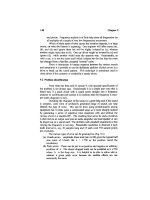
Back-Up Rings. Back-up rings, as shown in Figure 10-16, are often used
to prevent extrusion in high pressure applications, or to correct problems
such as spiral failure or nibbling. They are sometimes used in normal
pressure range applications to provide an added measure of protection or
to prolong O-ring life. These devices also permit the use of a wider
clearance gap when close tolerances are impossible to maintain.
A back-up ring is simply a ring made from a material harder than the
O-ring, designed to fit in the downstream side of the groove and close to
Protecting Machinery Parts Against Loss of Surface 599
the clearance gap to provide support for the O-ring. Quite often, O-rings
are used as back-up rings, even though back-up rings do not perform any
sealing function.
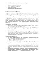
O-Ring, Back-Up Ring, and Gland Dimensions. O-ring sizes have been stan-
dardized and range in size from an inside diameter of 0.029 in. and a cross
Table 10-18
Gland Design Guide
INCHES MILLIMETERS
O-Ring Section .070 .103 .139 .210 .275 1.78 2.62 3.53 5.33 6.99
Diameter
STATIC SEALING
A Gland Depth .048 .077 .109 .168 .222 1.22 1.96 2.77 4.27 5.64
.054 .083 .115 .176 .232 1.37 2.11 2.92 4.47 5.89
B Groove Width .090 .140 .180 .280 .370 2.29 3.56 4.57 7.11 9.40
.100 .150 .190 .290 .380 2.54 3.81 4.83 7.37 9.65
R Groove Radius .015 .020 .025 .035 .050 .38 .51 .64 .89 1.27
(Max.)
DYNAMIC SEALING
A Gland Depth .055 .088 .120 .184 .234 1.40 2.24 3.05 4.67 5.94
.057 .090 .124 .188 .240 1.45 2.29 3.15 4.76 6.10
B Groove Width .090 .140 .180 .280 .370 2.29 3.56 4.57 7.11 9.40
.100 .150 .190 .290 .380 2.54 3.81 4.83 7.37 9.65
R Groove Radius .015 .020 .025 .035 .050 .38 .51 .64 .89 1.27
(Max.)
Figure 10-16. Back-up rings used with O-rings.
600 Machinery Component Maintenance and Repair
section of 0.040 in. to O-rings with an inside diameter of 16 or more in.
and a cross section of 0.210 or more in. Installation dimensions vary with
duty and application and the user may find it easy to consult manufactur-
ers’ catalogs, which are typically configured as shown in Figure 10-17.
Note the small differences in gland dimensions. They depend on whether
the O-ring will be axially squeezed, radially squeezed, or will perform
dynamic piston and rod sealing duty.
To calculate your own gland design, refer to Table 10-18, “Gland
Design Guide.”
Figure 10-17. A sampling of O-ring and gland dimensions.
Protecting Machinery Parts Against Loss of Surface 601
References
1. Bloch, H. P. and Geitner, F. K., Machinery Failure Analysis and Trou-
bleshooting, Gulf Publishing Company, Houston, Texas, Third
Edition, 1997, Pages 42–57.
2. Locke, J. J., “Cobalt Alloy Overlays in a Petro-Chemical Refinery,”
Cobalt, 1974, Vol. 2, Pages 25–31.
3. Mendenhall, M. D., “Shaft Overlays Proven Effective,” Hydrocarbon
Processing, May 1980, Pages 191–192.
4. Tribology Handbook, edited by M. J. Neale, John Wiley & Sons, New
York-Toronto, 1973, Page E13.
5. Chrome Plating, sales brochure by Exline, Inc., Salina, Kansas 67401.
6. Pyles, R., “Porous Chromium in Engine Cylinders,” Transactions of
the ASME, April 1944, Pages 205–214.
7. Tichvinsky, L. M. and Fischer, E. G., “Boundary Friction in Bearings
at Low Loads,” Transactions of the ASME, Vol. 61, 1939.
8. Reference 6, Page 206.
9. Reference 6, Page 210.
10. Vacca, A. P., “Extended Periods of Overhaul of Diesel Machinery,”
The Motor Ship, January 1964.
11. Mollerus, A. P. H. J., “Wear Data of Cylinder Liners,” study submit-
ted to Ingenieursbureau Lemet Chromium H., Van Der Horst N. V.,
November 1964.
12. Stinson, K. W., Diesel Engineering Handbook, Diesel Publications
Inc., Stamford, Connecticut, 1966.
13. Eichenour, C. and Edwards, V. H., “Electromechanical Metallizing
Saves Time in Rebuilding Engine Parts,” Plant Services, December
1982, Pages 49–50.
14. Correspondence with engineers for the Selectron Process, Metal
Surface Technology, Addison, Illinois 60101.
15. Republic Steel Corporation, “Heat Treatment of Steel,” Advertising
Booklet #1302Ra-10M-266, Cleveland, Ohio 44101, Pages 22–23.
16. Reference 15, Pages 24–25.
17. Reference 15, Pages 29–34.
18. Technical Bulletin by E.I. Du Pont de Nemours Co., Finishes Divi-
sion, Wilmington, Delaware.
19. Technical Bulletin by SR Metal Impregnation Co., Edmonton,
Alberta, Canada.
20. Moffat, J. D., “New Metal Impregnation Technology Solves Friction
and Corrosion Problems,” ASME, New York, New York, publication
No. 75-PEM-17, 1975, Pages 2–7.
Appendix 10-A
Part Documentation Record
Table 10-A-1
Typical Part Documentation Record Sheet
THE INTENT OF THIS FORM IS TO RECORD SPECIFIC PART CHARACTERISTICS
THAT WILL BE USED FOR FUTURE EVALUATION.
PART IDENTIFICATION ___________________________ UNIQUE ID ____________
CUSTOMER ________________________________ CUSTOMER P.O. _____________
INSPECTOR ______________________________ DATE ________________________
PST JOB NO. ______________________ DRAWING NO. _______________________
HARDNESS __________________ COATING TYPE ____________________________
OAL ________________ MAJOR DIAMETER _________________________________
LENGTH OF COATING FROM THE CROSSHEAD END OF THE SHAFT __________
LENGTH OF COATING ________________
MAGNAFLUX—ACCEPTED/REJECTED
COMMENTS ____________________________________________________________
________________________________________________________________________
________________________________________________________________________
________________________________________________________________________
602
Protecting Machinery Parts Against Loss of Surface 603
LOC DIMENSION TIR RMS
A
B
C
D
E
F
G
Table 10-A-1
Typical Part Documentation Record Sheet—cont’d
Source: Praxair Surface Technologies, Houston, Texas.
604 Machinery Component Maintenance and Repair
Table 10-A-2
Coating Designations and Physical Properties of Materials T
ypically Used by Praxair Surface
Technologies, Houston, Texas
Physical Properties
Average
Metallographic Evaluation
Typical
Coating Designation
Diamond Tensile Bond Strain to Max.
Coating
PST
AMS 2447B Pyramid Strength (psi) Fracture
Apparent
Interface Thickness
Coating Nominal Designation Hardness
ASTM C633 (in/in) Porosity Cracks Separation
Min/Max
Name Chemistry (Note 1) (Note 2)
(Note 3) (Note 4) (Note 5) (Note 6)
(Note 7) (Note 8)
LC-117 75CrC-25NiCr AMS 2447-3 775 (HV300)
>10,000 0.0020 1.0% None None 0.005/0.020
LW-102 83WC-17Co AMS 2447-7 1,095 (HV300)
>10,000 0.0021 1.0% None None 0.005/0.020
LW-103 86WC-10Co- AMS 2447-9 950 (HV300)
>10,000 0.0023 0.75% None None 0.005/0.020
4Cr
LW-104 90WC-10Ni AMS 2447-10 1,075 (HV300)
>10,000 0.0032 0.5% None None 0.005/0.020
LN-120 IN 718: 53Ni- AMS 2447-6 400 (HV300)
>10,000 0.0066 0.5% None None 0.015/0.050
20Cr-19Fe-
5(Nb +
Ta)-3Ti
Protecting Machinery Parts Against Loss of Surface 605
Table 10-A-2
Coating Designations and Physical Properties of Materials T
ypically Used by Praxair Surface
Technologies, Houston, Texas—cont’d
Physical Properties
Average
Metallographic Evaluation
Typical
Coating Designation
Diamond Tensile Bond Strain to Max.
Coating
PST
AMS 2447B Pyramid Strength (psi) Fracture
Apparent
Interface Thickness
Coating Nominal Designation Hardness
ASTM C633 (in/in) Porosity Cracks Separation
Min/Max
Name Chemistry (Note 1) (Note 2)
(Note 3) (Note 4) (Note 5) (Note 6)
(Note 7) (Note 8)
The properties for the following coating are based on limited data.
LN-121 72Ni-16Cr-4Si- N/A
500 (HV300)
>9,000 Not 2.0% None None 0.005/0.040
3.5B-4Fe 8C
available
Note 1: The AMS 2447B designation is to be used as a cross reference for chemical composition onl
y. Additional testing for specific coating
applications would be required to meet the requirements of AMS 2447B
.
Note 2: Average diamond pyramid hardness is based on coating at an optimum spra
y angle and distance. Actual hardness on a particular part
will vary based on part geometry.
Note 3: Bond strength results are based on 1,018 steel specimens coated and tested per
ASTM C633. This test is limited by strength of the
epoxy used. Bond strength can also vary depending on the specimen material used.
Note 4: Strain to fracture is a measure of ductility using a four-point bend test de
veloped by Praxair Surface Technologies.
Note 5: Maximum apparent porosity is determined by examining a coupon coated at an optimum spra
y and distance. A cross section of the
coupon is examined at 200
¥ and compared to photographic standards. Actual porosity on a par
t will be influenced b
y part geometry.
Note 6: Presence of cracking is evaluated by examining a coupon coated at an optimum spra
y and distance. A cross section of the
coupon
is examined at 200¥.
Note 7: Interface separation is evaluated by examining a coupon coated at an optimum spra
y and distance. A cross section of the coupon is
examined at 200¥.
Note 8: Typical coating thickness should be used as a reference only
. The coating thickness for a specific part must be evaluated based on
factors such as part material type, part geometry, and type of service.
606 Machinery Component Maintenance and Repair
Table 10-A-3
Common Repair Methods and Preferred Selection Sequence
Common Repair Methods
Preferred Selection 1-2-3-4
LC-117 LW-102 LW-103 LW-104 LN-120 LN-121
Bearing Journal 1 3 2 4
Thrust Collar Fits 1 3 2 4
Keyed Coupling Fits 2 1
HP-LP Seal Areas 1 2 4 3
Barrel Keyed Wheel Fits 2 1
Inner Stage Seal Areas 3 4 2 1
Impeller Eyes 2 4 3 1
Balance Piston and 1 2
Impeller Bores
Balance Piston Diameter 1 2 4 3
Laby Hi-Lo Sections 1
Hydraulic Tapered 1 2
Coupling
LW-103 should be considered where additional corrosion and abrasion resistance is
needed.
Source: Praxair Surface Technologies, Houston, Texas.
Table 10-A-4
Fusion High Velocity Oxygen Fuel (HVOF) Coating Procedure for
Repair of Industrial Crankshafts
Scope
Listed on this document are approved standards to be used in the repair of a crankshaft
when a customer specification, or no other specification, exists. A customer drawing or
specification will always be used in place of these standards. The HVOF repair method
will provide a much harder surface than original hardness of substrate, while offering
the bond strength and optimum density of compressive coatings. This will allow
resistance to wear and corrosion. It is not intended to restore tensile or torsional
strength.
Diameter Tolerance:
Rod journal diameter: +0/-0.001≤
Main journal diameter: +0/-0.001≤
Gear fits: +0/-0.001≤
Seal areas: +0/-0.001≤
Circular Runout Limits:
Main journals: 0.002≤ total indicator reading (T.I.R.); crankshaft supported at each end.
Protecting Machinery Parts Against Loss of Surface 607
Table 10-A-4
Fusion HVOF Coating Procedure for Repair
of Industrial Crankshafts—cont’d
Roundness Limits:
All diameters: 50 percent of the available diameter tolerance. For example; if the
diameter tolerance is 0.001≤, roundness limit will be 0.0005≤.
Taper Limits (Parallelism):
All diameters: 50% of the available diameter tolerance. For example; if the diameter
tolerance is 0.001≤, taper limit will be 0.0005≤.
Surface Finish (Average):
Regrinds:
Rod and main journals: 16 rms
Seal areas: 16 rms
All other diameters: 16–32 rms
With HVOF Coating—Chrome Carbide or Nickel-Chromium Self-Fluxing Alloy:
Rod and main journals: 16 rms
Seal areas: 16 rms
Gear fits: 16 rms: minimal grinding marks are acceptable
Tapered snouts: 16rms and 85 percent + blue contact
All other diameters: 16–32 rms: minimal grinding marks are acceptable
1.0 Scope
1.1 This document describes a process for rebuilding worn crankshaft journals and
other fits with HVOF coating(s). It will apply to crankshafts that require ABS
(American Bureau of Shipping) certification.
1.2 This HVOF procedure will be qualified by testing in accordance with bond
tests per ASTM C633.
2.0 Associated Documents
• Bond Test Results (ASTM C633)
• Crankshaft Inspection Reports (FI-007 and FI-008)
• ASTM B499-88 Standard Test Method for measurement of coating/plating
thickness by the magnetic method
• Grit Blasting Parameter (FI-7-10 Procedure)
• HVOF Coating Parameter (FI-3-110 Procedure) Nickel-Chromium Self-
Fluxing Alloy
• HVOF Coating Parameter (FI-3-60 Procedure) Chrome Carbide
2.1 Copies of these documents are available from the Q.A. Manager or Operations
Manager.
2.2 Drawings provided by manufacturer or sketch of crankshaft with size,
tolerance, etc. provided by customer.
(Text continued on next page)
608 Machinery Component Maintenance and Repair
Table 10-A-4
Fusion HVOF Coating Procedure for Repair
of Industrial Crankshafts—cont’d
3.0 Cleaning
3.1 Remove all parts that are needed to completely clean and inspect the
crankshaft. Mark these parts with the fusion job number.
3.2 Remove all plugs and check all oil holes for blockage; clear oil passages as
necessary.
3.3 In a location not to cause damage, stamp the crankshaft with the issued job
number.
3.4 Place the crankshaft in a hot caustic solution until oil and grease are no longer
present.
3.5 Remove the crankshaft from caustic tank, then steam clean, flushing oil ports,
and rinse the entire shaft.
4.0 Initial Inspection (use initial inspection report FI-007)
4.1 Inspect and record the “as received” dimensions of the crankshaft; this includes
the bearing journals, thrust width(s), seal fits, gear fits, and coupling fits. If
tapered, small end will be measured and any fretting noted.
4.2 Visually inspect and record the overall condition of the above-mentioned areas,
plus any threaded holes and keyways.
4.3 Check and record hardness of crankshaft. This to be performed on at least (1)
main and (1) rod journal. If any rub or “hot spot” is noticeable, document
hardness of area(s) before and after pregrind. If hardness goes beyond 50 Rc,
contact customer for alternate or extended repair required.
4.4 If the crankshaft has been previously repaired, check and record the depth of
the coating or chrome on each journal. If shaft has been welded, note on space
provided.
4.5 Inspect and record the total indicator run-out of each main bearing journal.
This can be performed in V-blocks, or, for larger shafts, in crank grinding
machine with proper supports in place.
4.6 Using the magnetic particle method, inspect the crankshaft for cracks or other
indications.
4.7 Shaft will be degaussed to a residual level of 2 or less.
Author’s Note: Good procedures ensure good workmanship!
Protecting Machinery Parts Against Loss of Surface 609
Table 10-A-4
Fusion HVOF Coating Procedure for Repair
of Industrial Crankshafts—cont’d
Note: When required, an inspector may elect to be present during any or all of the
preinspection steps. Their purpose will be as follows:
• To witness magnetic particle examination of the crankshaft to ensure
inspection is performed by a certified level II/III inspector.
• To view the initial inspection reports, work order recording of the operations
that have been completed, information recorded, and initialed.
• To visually inspect the crankshaft for any previous stamps, markings, or signs
of damage.
Option: An ultrasonic inspection can be performed to detect subsurface cracks or
flaws in the substrate. This will be performed by outside level III inspector at our
facility.
5.0 Straightening
5.1 Straightening may be done on crankshafts that are bent more than 0.010≤. This
can be done by peening or by straightening in a hydraulic press. No heat will
be applied to a crankshaft for straightening purposes.
6.0 Pregrind Operation
6.1 Grinding wheels used to undercut diameters are to be dressed with a corner
radius that conforms with the journal’s radius.
6.2 The journal diameters are to be undercut to a diameter that will leave a final
minimum coating thickness of between 0.005≤ and 0.010≤ after finish grinding,
or to the undersize limits specified by the OEM (original equipment
manufacturer). A maximum of 0.050≤ on diameter will be removed if required
to remove wear or damage. Alternate repair methods are available if undercut is
beyond these limits.
6.3 If there are any “hot spots” or rubs that have discolored the shaft, these areas
will, after pregrind, be checked for hard spots.
7.0 Secondary Magnaflux Inspection
7.1 After undercutting a magnetic examination will be performed by a certified
level II or III inspector.
7.2 Shaft will be degaussed to a residual level of 2 or less.
8.0 HVOF Coating
8.1 The crankshaft will be masked and taped off on all areas not to be coated. Oil
holes will be plugged to protect from overspray or damage.
(Text continued on next page)
610 Machinery Component Maintenance and Repair
Table 10-A-4
Fusion HVOF Coating Procedure for Repair
of Industrial Crankshafts—cont’d
8.2 Grit blast with aluminum oxide grit, using only new grit, to attain desired
anchor profile on areas to be coated. Use Fusion FI-7-10 Parameter Procedure
for this purpose.
8.3 Journals will be sprayed using either HVOF Chrome Carbide coating or HVOF
Nickel-Chromium Self-Fluxing Alloy coating. Keyed fits, such as coupling
areas, will be sprayed with HVOF Nickel-Chromium Self-Fluxing Alloy
coating. The coating, as sprayed, will allow for finish grind stock. Use FI-3-60
or FI-3-110 Parameter Procedure for this purpose.
8.4 Document temperature of area(s) coated at point of contact using an infrared
gun. This temperature will not exceed 350°F maximum temperature.
8.5 After coating, allow the crankshaft to cool in still air to ambient temperature.
8.6 Record the lot number and the type of coating powder used.
Note: A sample coating coupon. for metallurgical evaluation, can be provided upon
request.
9.0 Finish Grinding
9.1 Grind journal diameters to specified OEM dimensions. A diamond grinding
wheel will be used to grind journals within 0.001≤ of finish size.
9.2 Dye penetrant inspect coating.
9.3 All journals will be diamond honed to size and RMS requirement.
10.0 Polishing
10.1 De-burr and polish all oil ports and journal radii to be smooth of any sharp
edges or scratches. Radii to be free of any blemishes.
11.0 Final Inspection
11.1 Visually inspect all repaired areas for signs of blemishes and defects.
11.2 Inspect and record the dimensions of all repaired areas on a crankshaft final
inspection report (FI-008).
11.3 Record final T.I.R. of each main journal.
11.4 Inspect and record the coating thickness. Micrometers are to be used to
measure coating thickness.
Protecting Machinery Parts Against Loss of Surface 611
Table 10-A-4
Fusion HVOF Coating Procedure for Repair
of Industrial Crankshafts—cont’d
11.5 Document journal(s) rms using profilometer.
Note: ABS to witness final inspection, when required.
12.0 Shipment
12.1 Clear all oil passages and reinstall counterweights if needed.
12.2 Locate and install any other loose components, or parts that were removed
from crankshaft, before packaging.
12.3 Review work order to ensure all operations and inspections were completed.
12.4 Apply a rust preventative and prepare for shipment per customer requirement.
Author’s Note: Insist on reviewing written repair procedures. Ask the repair specialists for
explanation of steps needed to achieve high-quality results!
612 Machinery Component Maintenance and Repair
Table 10-A-5
Documentation (Typical Only) Identifying Procedure Changes
from a Previous Revision
Fusion High Velocity Oxygen Fuel (HVOF) Coating Procedure for
Repair of Industrial Crankshafts: Changes from Revision 5 to
Revision 6
Header:
From: Revision No.: 5
To: Revision No.: 6
From: Effective date: 10/30/98
To: Effective date: 07/09/99
Surface Finish (Average):
From: With HVOF Coating—Chrome Carbide of Inconel
To: With HVOF Coating—Chrome Carbide or Nickel-Chromium Self-Fluxing
Alloy
2.0 Associated Documents
From: HVOF Coating Parameter (FI-3-50 Procedure) Inconel
To: HVOF Coating Parameter (FI-3-110 Procedure) Nickel-Chromium Self-
Fluxing Alloy
4.7 Note:
From: Note: An ABS inspector may elect to be present during any or all of the
preinspection steps. Their purpose will be as follows:
To: Note: When required, ABS inspector may elect to be present during any or
all of the preinspection steps. Their purpose will be as follows:
8.3
From: Journals will be sprayed using an HVOF Chrome Carbide coating. An HVOF
Inconel coating will be sprayed on any keyed fit, such as coupling area. The
coating, as sprayed, will allow for finish grind stock. Use FI-3-50 or FI-3-60
Parameter Procedure for this purpose.
To: Journals will be sprayed using either HVOF Chrome Carbide coating or HVOF
Nickel-Chromium Self-Fluxing Alloy coating. Keyed fits, such as coupling
areas, will be sprayed with HVOF Nickel-Chromium Self-Fluxing Alloy
coating. The coating, as sprayed, will allow for finish grind stock. Use FI-3-60
or FI-3-110 Parameter Procedure for this purpose.
Source: Praxair Surface Technologies, Houston, Texas.
Author’s Note: Revised procedures must document changes that enhance component
reliability.
Protecting Machinery Parts Against Loss of Surface 613
Table 10-A-6
Repair Procedure for Piston Rods and Plungers
High Velocity Liquid Fuel (HVLF) Tungsten Carbide Procedure for
Tafa JP-5000 Repair of Piston Rods and Plungers
1. Rod will be checked for straightness, amount of wear, thread damage, piston fit
size, etc., and findings documented in as “received condition.” Hardness of
packing/wiper section will also be documented.
2. Unless specified differently by customer, packing and wiper ring section plus at
least
1
/
2
≤ at each end of area shall be ground undersize to remove damage and wear.
Edge of undercut will have a radius to prevent possible stress riser from occurring.
Document hardness after undercut. If previously coated, all old coating will be
removed.
Note: On rods previously coated, there is an option to chemically remove the old
coating without grinding. This is done in house.
3. Rod will be magnetic particle inspected to check for cracks throughout shaft. Rod
shall be demagnetized after inspection to a residual level of 2 gauss or less. As an
option, a customer may also request ultrasonic inspection of a rod.
4. Rod will then be masked and taped off with surface protection for all surfaces
except those to be grit blasted.
5. An aluminum oxide grit will be used in grit blasting to provide a surface finish of
200 to 350 rms for coating. We use only new grit for this purpose.
6. Within 2 hours of the grit blast operation, an HVLF (3,300–3,900 feet per second
[FPS] particle velocity) Tafa JP-5000 tungsten carbide overlay shall be used on
packing/wiper sections. The rod temperature during coating application shall not
exceed 350°F. We verify this using an infrared gun directed at point of jet stream at
rod impact zone.
Note: There are several tungsten carbide chemical compositions available.
Depending on the type of service rod will see, we will determine, with customer
approval, the proper composition of tungsten carbide and bonding matrix best suited
for this particular application.
7. Coating shall be applied on the diameter 0.010≤ to 0.015≤ greater than the specified
finish diameter. As an option, and when required, an application of a proprietary
UCAR 100 sealer will immediately follow the coating process. Please note that rods
that are in oxygen service should never be sealed!
Note: If required, at this step, we can attach a coupon of like material substrate to
be sprayed with the rod. This coupon will be supplied to the customer for any
metallurgical examination you may wish to perform.
8. Rod will be finish ground with a diamond wheel, diamond honed, and super-
finished to the desired rms required. This is determined by discharge pressure and
will be discussed with customer prior to beginning repair. All reliefs and radii will
be polished.
9. Dye penetrant check will be performed for final inspection against any indication of
blisters, spalling, flaking, cracking, or pits.
10. Unless otherwise specified, rod shall be preserved and crated with proper supports
in place, per customer requirements.
(Text continued on next page)
614 Machinery Component Maintenance and Repair
Table 10-A-6
Repair Procedure for Piston Rods and Plungers
High Velocity Liquid Fuel (HVLF) Tungsten Carbide Procedure for
Tafa JP-5000 Repair of Piston Rods and Plungers—cont’d
11. PST will record work performed on rod which includes:
a. Rod will be stamped on one end with PST job number
b. All dimensional checks
c. RC hardness
d. Magnaflux results
e. Conditions “as received” and corrections made
f. Coating lengths and thickness of coating
g. Type of coating and lot number used for repair
h. Final rms finish documented with profilometer tape
Above information will be made available upon request.
The Tafa JP-5000 HVLF system provides a dense wear-resistant sprayed coating with very
good surface smoothness (1–2 rms attainable due to density of coatings) and bond strength
greater than 10,000 lb, per ASTM C-633 tests.
Source: Praxair Surface Technologies, Houston, Texas.
Author’s Note: Good repair shops will document
(a) what they will do (“necessary steps”)
(b) how they have carried out the necessary steps
(c) inspection results (testing and/or measurements).