Machinery''''s Handbook 27th Episode 3 Part 4 doc
Bạn đang xem bản rút gọn của tài liệu. Xem và tải ngay bản đầy đủ của tài liệu tại đây (528.3 KB, 54 trang )
CENTRALIZING ACME SCREW THREADS 1835
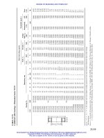
Table 6. American National Standard Centralizing Acme Screw Thread Form —
Basic Dimensions ASME/ANSI B1.5-1988
Thds
per
Inch,
n
Pitch,
P
Height of
Thread
(Basic),
h = P/2
Total Height
of Thread
(All External
Threads)
h
s
= h +
1
⁄
2
allowance
a
Thread
Thickness
(Basic),
t = P/2
45-Deg Chamfer Crest of
External Threads
Max Fillet
Radius,
Root of
Tapped
Hole,
0.06P
Fillet Radius
at Min or
Diameter
of Screws
Max (All)
0.10P
Min
Depth,
0.05P
Min Width
of Chamfer
Flat,
0.0707P
16 0.06250 0.03125 0.0362 0.03125 0.0031 0.0044 0.0038 0.0062
14 0.07143 0.03571 0.0407 0.03571 0.0036 0.0050 0.0038 0.0071
12 0.08333 0.04167 0.0467 0.04167 0.0042 0.0059 0.0050 0.0083
10 0.10000 0.05000 0.0600 0.05000 0.0050 0.0071 0.0060 0.0100
8 0.12500 0.06250 0.0725 0.06250 0.0062 0.0088 0.0075 0.0125
6 0.16667 0.08333 0.0933 0.08333 0.0083 0.0119 0.0100 0.0167
5 0.20000 0.10000 0.1100 0.10000 0.0100 0.0141 0.0120 0.0200
4 0.25000 0.12500 0.1350 0.12500 0.0125 0.0177 0.0150 0.0250
3 0.33333 0.16667 0.1767 0.16667 0.0167 0.0236 0.0200 0.0333
2
1
⁄
2
0.40000 0.20000 0.2100 0.20000 0.0200 0.0283 0.0240 0.0400
2 0.50000 0.25000 0.2600 0.25000 0.0250 0.0354 0.0300 0.0500
1
1
⁄
2
0.66667 0.33333 0.3433 0.33333 0.0330 0.0471 0.0400 0.0667
1
1
⁄
3
0.75000 0.37500 0.3850 0.37500 0.0380 0.0530 0.0450 0.0750
1 1.00000 0.50000 0.5100 0.50000 0.0500 0.0707 0.0600 0.1000
All dimensions in inches. See Fig. 3.
a
Allowance is 0.020 inch for 10 or less threads per inch and 0.010 inch for more than 10 threads per
inch.
Fig. 3. Centralizing Acme Screw Thread Form
Machinery's Handbook 27th Edition
Copyright 2004, Industrial Press, Inc., New York, NY
1836 CENTRALIZING ACME SCREW THREADS
est number of items in order to reduce to a minimum the inventory of both tools and gages.
This series of diameters and associated pitches is given in Table 9.
Basic Diameters: The maximum major diameter of the external thread is basic and is the
nominal major diameter for all classes.
The minimum pitch diameter of the internal thread is basic for all classes and is equal to
the basic major diameter D minus the basic height of thread, h. The minimum minor diam-
eter of the internal thread for all classes is 0.1P above basic.
Length of Engagement: The tolerances specified in this Standard are applicable to
lengths of engagement not exceeding twice the nominal major diameter.
Pitch Diameter Allowances: Allowances applied to the pitch diameter of the external
thread for all classes are given in Table 10.
Major and Minor Diameter Allowances: A minimum diametral clearance is provided at
the minor diameter of all external threads by establishing the maximum minor diameter
0.020 inch below the basic minor diameter for 10 threads per inch and coarser, and 0.010
inch for finer pitches and by establishing the minimum minor diameter of the internal
thread 0.1P greater than the basic minor diameter.
Table 7. Formulas for Finding Basic Dimensions of
Centralizing Acme Screw Threads
Pitch = P = 1 ÷ No. threads per inch, n: Basic thread height h = 0.5P
Basic thread thickness t = 0.5P
Basic flat at crest F
cn
= 0.3707P + 0.259 × (minor. diameter allowance on internal threads) (internal thread)
Basic flat at crest F
cs
= 0.3707P − 0.259 × (pitch diameter allowance on external thread) (external thread)
F
rn
= 0.3707P − 0.259 × (major dia. allowance on internal thread)
F
rs
= 0.3707P − 0.259 × (minor dia. allowance on external thread — pitch dia. allowance on external thread)
Fig. 4. Disposition of Allowances, Tolerances, and Crest Clearances for Centralizing
Single-Start Acme Threads—Classes 2C, 3C, and 4C
r
1
r
N
r
S
r
N
= 0.06P Max
r
S
= 0.1P max
0.0945P Max
0.0707P Min
Detail of chamfer
Detail of fillet
Detail of optional fillet
One half minor dia.
allowance (screw)
Internal Thread (Nut)
External Thread
(Screw)
45°
P
4
0.067P Max
0.050P Min
One-half major dia. allowance (nut)
Max major dia. of nut
Min major dia. of nut
Nominal (basic) major dia. (D)
Max major dia. of screw
Max pitch dia. of screw
Min pitch dia. of screw
Basic pitch dia.
1/2 pitch dia. allowance
Max minor dia. of nut
Min minor dia. of nut
Basic minor dia.
Max minor dia. of screw
Min minor dia. of screw
Min pitch dia. of nut
Max pitch dia. of nut
One-half minor dia. allowance (nut)
0.05P
Min major dia. of screw
Min depth of engagement
P
4
h – 0.05P
h
Symbols:
P = pitch
h = basic thread height
Machinery's Handbook 27th Edition
Copyright 2004, Industrial Press, Inc., New York, NY
CENTRALIZING ACME SCREW THREADS 1837
A minimum diametral clearance at the major diameter is obtained by establishing the
minimum major diameter of the internal thread above the basic major diameter.
These allowances are shown in Table 12.
Major and Minor Diameter Tolerances: The tolerances on the major and minor diame-
ters of the external and internal threads are listed in Table 12 and are based upon the formu-
las given in the column headings.
An increase of 10 per cent in the allowance is recommended for each inch or fraction
thereof that the length of engagement exceeds two diameters.
For information on gages for Centralizing Acme threads the Standard ASME/ANSI B1.5
should be consulted.
Pitch Diameter Tolerances: Pitch diameter tolerances for Classes 2C, 3C and 4C for var-
ious practicable combinations of diameter and pitch are given in Table 11. The ratios of the
pitch diameter tolerances of Classes 2C, 3C, and 4C are 3.0, 1.4, and 1, respectively.
Application of Tolerances: The tolerances specified are such as to insure interchange-
ability and maintain a high grade of product. The tolerances on the diameters of internal
threads are plus, being applied from the minimum sizes to above the minimum sizes. The
tolerances on the diameters of external threads are minus, being applied from the maxi-
mum sizes to below the maximum sizes. The pitch diameter tolerances for an external or
internal thread of a given class are the same
Limiting Dimensions: Limiting dimensions for Centralizing Acme threads in the pre-
ferred series of diameters and pitches are given in Tables 8b and 8c. These limits are based
on the formulas in Table 8a.
For combinations of pitch and diameter other than those in the preferred series the formu-
las in Tables 8b and 8c and the data in the tables referred to therein make it possible to
readily determine the limiting dimension required.
Table 8a. American National Standard Centralizing Acme Single-Start Screw
Threads — Formulas for Determining Diameters ASME/ANSI B1.5-1988
D = Nominal Size or Diameter in Inches
P = Pitch = 1 ÷ Number of Threads per Inch
No. Classes 2C, 3C, and 4C External Threads (Screws)
1 Major Dia., Max = D (Basic).
2 Major Dia., Min = D minus tolerance from Table 12, columns 7, 8, or 10.
3 Pitch Dia., Max = Int. Pitch Dia., Min (Formula 9) minus allowance from the appropri-
ate Class 2C, 3C, or 4C column of Table 10.
4 Pitch Dia., Min = Ext. Pitch Dia., Max (Formula 3) minus tolerance from Table 11.
5 Minor Dia., Max = D minus P minus allowance from Table 12, column 3.
6 Minor Dia., Min = Ext. Minor Dia., Max (Formula 5) minus 1.5 × Pitch Dia. tolerance
from Table 11.
Classes 2C, 3C, and 4C Internal Threads (Nuts)
7 Major Dia., Min = D plus allowance from Table 12, column 4.
8 Major Dia., Max = Int. Major Dia., Min (Formula 7) plus tolerance from Table 12, col-
umns 7, 9, or 11.
9 Pitch Dia., Min = D minus P/2 (Basic).
10 Pitch Dia., Max = Int. Pitch Dia., Min (Formula 9) plus tolerance from Table 11.
11 Minor Dia., Min = D minus 0.9P.
12 Minor Dia., Max = Int. Minor Dia., Min (Formula 11) plus tolerance from Table 12,
column 6.
0.001 D
Machinery's Handbook 27th Edition
Copyright 2004, Industrial Press, Inc., New York, NY
STUB ACME SCREW THREADS 1843
Designation of Centralizing Acme Threads.—The following examples are given to
show how these Acme threads are designated on drawings, in specifications, and on tools
and gages:
Example, 1.750-6-ACME-4C:Indicates a Centralizing Class 4C Acme thread of 1.750-
inch major diameter, 0.1667-inch pitch, single thread, right-hand.
Example, 1.750-6-ACME-4C-LH:Indicates the same thread left-hand.
Example, 2.875-0.4P-0.8L-ACME-3C (Two Start):Indicates a Centralizing Class 3C
Acme thread with 2.875-inch major diameter, 0.4-inch pitch, 0.8-inch lead, double thread,
right-hand.
Example, 2.500-0.3333P-0.6667L-ACME-4C (Two Start):Indicates a Centralizing
Class 4C Acme thread with 2.500-inch nominal major diameter (basic major diameter
2.500 inches), 0.3333-inch pitch, 0.6667-inch lead, double thread, right-hand. The same
thread left-hand would have LH at the end of the designation.
Acme Centralizing Threads—Alternative Series with Minor Diameter Centralizing
Control.—When Acme centralizing threads are produced in single units or in very small
quantities (and principally in sizes larger than the range of commercial taps and dies)
where the manufacturing process employs cutting tools (such as lathe cutting), it may be
economically advantageous and therefore desirable to have the centralizing control of the
mating threads located at the minor diameters.
Particularly under the above-mentioned type of manufacturing, the two advantages cited
for minor diameter centralizing control over centralizing control at the major diameters of
the mating threads are: 1) Greater ease and faster checking of machined thread dimen-
sions. It is much easier to measure the minor diameter (root) of the external thread and the
mating minor diameter (crest or bore) of the internal thread than it is to determine the major
diameter (root) of the internal thread and the major diameter (crest or turn) of the external
thread; and 2) better manufacturing control of the machined size due to greater ease of
checking.
In the event that minor diameter centralizing is necessary, recalculate all thread dimen-
sions, reversing major and minor diameter allowances, tolerances, radii, and chamfer.
American National Standard Stub Acme Threads.—This American National Stan-
dard ASME/ANSI B1.8-1988 (R2001) provides a Stub Acme screw thread for those
unusual applications where, due to mechanical or metallurgical considerations, a coarse-
pitch thread of shallow depth is required. The fit of Stub Acme threads corresponds to the
Class 2G General Purpose Acme thread in American National Standard ANSI B1.5-1988.
For a fit having less backlash, the tolerances and allowances for Classes 3G or 4G General
Purpose Acme threads may be used.
Thread Form: The thread form and basic formulas for Stub Acme threads are given on
page 1826 and the basic dimensions in Table 13.
Allowances and Tolerances: The major and minor diameter allowances for Stub Acme
threads are the same as those given for General Purpose Acme threads on page 1825.
Pitch diameter allowances for Stub Acme threads are the same as for Class 2G General
Purpose Acme threads and are given in Table 4. Pitch diameter tolerances for Stub Acme
threads are the same as for Class 2G General Purpose Acme threads given in Table 5.
Limiting Dimensions: Limiting dimensions of American Standard Stub Acme threads
may be determined by using the formulas given in Table 14a, or directly from Table 14b.
The diagram below shows the limits of size for Stub Acme threads.
Thread Series: A preferred series of diameters and pitches for General Purpose Acme
threads (Table 15) is recommended for Stub Acme threads.
Machinery's Handbook 27th Edition
Copyright 2004, Industrial Press, Inc., New York, NY
1846 ALTERNATIVE CENTRALIZING ACME SCREW THREADS
Stub Acme Thread Designations.—The method of designation for Standard Stub Acme
threads is illustrated in the following examples: 0.500-20 Stub Acme indicates a
1
⁄
2
-inch
major diameter, 20 threads per inch, right hand, single thread, Standard Stub Acme thread.
The designation 0.500-20 Stub Acme-LH indicates the same thread except that it is left
hand.
Alternative Stub Acme Threads.—Since one Stub Acme thread form may not meet the
requirements of all applications, basic data for two of the other commonly used forms are
included in the appendix of the American Standard for Stub Acme Threads. These so-
called Modified Form 1 and Modified Form 2 threads utilize the same tolerances and
allowances as Standard Stub Acme threads and have the same major diameter and basic
thread thickness at the pitchline (0.5P). The basic height of Form 1 threads, h, is 0.375P;
for Form 2 it is 0.250P. The basic width of flat at the crest of the internal thread is 0.4030P
for Form 1 and 0.4353P for Form 2.
The pitch diameter and minor diameter for Form 1 threads will be smaller than similar
values for the Standard Stub Acme Form and for Form 2 they will be larger owing to the
differences in basic thread height h. Therefore, in calculating the dimensions of Form 1 and
Form 2 threads using Formulas 1 through 12 in Table 14a, it is only necessary to substitute
the following values in applying the formulas: For Form 1, D
2
= D − 0.375P, D
1
= D −
0.75P; for Form 2, D
2
= D − 0.25P, D
1
= D − 0.5P.
Thread Designation: These threads are designated in the same manner as Standard Stub
Acme threads except for the insertion of either M1 or M2 after “Acme.” Thus, 0.500-20
Stub Acme M1 for a Form 1 thread; and 0.500-20 Stub Acme M2 for a Form 2 thread.
Former 60-Degree Stub Thread.—Former American Standard B1.3-1941 included a
60-degree stub thread for use where design or operating conditions could be better satisfied
by the use of this thread, or other modified threads, than by Acme threads. Data for 60-
Degree Stub thread form are given in the accompanying diagram.
Limits of Size, Allowances, Tolerances, and Crest Clearances for
American National Standard Stub Acme Threads
External Thread
(Screw)
Internal Thread
(Nut)
Basic thickness of thread, P/2
One-half
major dia.
allowance
One-half
major dia.
allowance
Max minor dia. of nut
Basic pitch dia.
Min minor dia. of nut
Basic minor dia.
Max minor dia. of screw
Min minor dia. of screw
Min minor dia. of screw
Min pitch dia. of nut
1/2 Pitch dia. allowance
Max pitch dia.
of screw
Min pitch dia.
of screw
h
Max major dia. of nut
Min major dia. of nut
Nominal (basic) major dia. (D)
Max major dia. of screw
Min major dia. of screw
Min depth of
engagement
0.15P
0.15P
P′
Machinery's Handbook 27th Edition
Copyright 2004, Industrial Press, Inc., New York, NY
1848 ALTERNATIVE CENTRALIZING ACME SCREW THREADS
60-Degree Stub Thread
A clearance of at least 0.02 × pitch is added to depth h to produce extra depth, thus avoid-
ing interference with threads of mating part at minor or major diameters.
Basic thread thickness at pitch line = 0.5 × pitch p; basic depth h = 0.433 × pitch; basic
width of flat at crest = 0.25 × pitch; width of flat at root of screw thread = 0.227 × pitch;
basic pitch diameter = basic major diameter − 0.433 × pitch; basic minor diameter = basic
major diameter − 0.866 × pitch.
Square Thread.—The square thread is so named because the section is square, the depth,
in the case of a screw, being equal to the width or one-half the pitch. The thread groove in a
square-threaded nut is made a little greater than one-half the pitch in order to provide a
slight clearance for the screw; hence, the tools used for threading square-threaded taps are
a little less in width at the point than one-half the pitch. The pitch of a square thread is usu-
ally twice the pitch of an American Standard thread of corresponding diameter. The square
thread has been superseded quite largely by the Acme form which has several advantages.
See ACME SCREW THREADS.
10-Degree Modified Square Thread: The included angle between the sides of the thread
is 10 degrees (see accompanying diagram). The angle of 10 degrees results in a thread
which is the practical equivalent of a “square thread,” and yet is capable of economical pro-
duction. Multiple thread milling cutters and ground thread taps should not be specified for
modified square threads of the larger lead angles without consulting the cutting tool man-
ufacturer.
In the following formulas, D = basic major diameter; E = basic pitch diameter; K = basic
minor diameter; p = pitch; h = basic depth of thread on screw depth when there is no clear-
ance between root of screw and crest of thread on nut; t = basic thickness of thread at pitch
line; F = basic width of flat at crest of screw thread; G = basic width of flat at root of screw
thread; C = clearance between root of screw and crest of thread on nut: E = D − 0.5p; K = D
− p; h = 0.5p (see Note); t = 0.5p; F = 0.4563p; G = 0.4563p − (0.17 × C).
Note: A clearance should be added to depth h to avoid interference with threads of mating
parts at minor or major diameters.
0.4563p
Pitch
Diameter
Allowance
G
0.25p
0.25p
Clearance (See Note)
Clearance (See Note)
p
2
p
2
1
2
h
5˚
Screw
Nut
Machinery's Handbook 27th Edition
Copyright 2004, Industrial Press, Inc., New York, NY
BUTTRESS THREADS 1849
BUTTRESS THREADS
Threads of Buttress Form
The buttress form of thread has certain advantages in applications involving exception-
ally high stresses along the thread axis in one direction only. The contacting flank of the
thread, which takes the thrust, is referred to as the pressure flank and is so nearly perpen-
dicular to the thread axis that the radial component of the thrust is reduced to a minimum.
Because of the small radial thrust, this form of thread is particularly applicable where tubu-
lar members are screwed together, as in the case of breech mechanisms of large guns and
airplane propeller hubs.
Fig. 1a shows a common form. The front or load-resisting face is perpendicular to the
axis of the screw and the thread angle is 45 degrees. According to one rule, the pitch P = 2
× screw diameter ÷ 15. The thread depth d may equal
3
⁄
4
× pitch, making the flat f =
1
⁄
8
×
pitch. Sometimes depth d is reduced to
2
⁄
3
× pitch, making f =
1
⁄
6
× pitch.
The load-resisting side or flank may be inclined an amount (Fig. 1b) ranging usually from
1 to 5 degrees to avoid cutter interference in milling the thread. With an angle of 5 degrees
and an included thread angle of 50 degrees, if the width of the flat f at both crest and root
equals
1
⁄
8
× pitch, then the thread depth equals 0.69 × pitch or
3
⁄
4
d
1
.
The saw-tooth form of thread illustrated by Fig. 1c is known in Germany as the
“Sägengewinde” and in Italy as the “Fillettatura a dente di Sega.” Pitches are standardized
from 2 millimeters up to 48 millimeters in the German and Italian specifications. The front
face inclines 3 degrees from the perpendicular and the included angle is 33 degrees.
The thread depth d for the screw = 0.86777 × pitch P. The thread depth g for the nut = 0.75
× pitch. Dimension h = 0.341 × P. The width f of flat at the crest of the thread on the screw
= 0.26384 × pitch. Radius r at the root = 0.12427 × pitch. The clearance space e = 0.11777
× pitch.
British Standard Buttress Threads BS 1657: 1950.—Specifications for buttress
threads in this standard are similar to those in the American Standard (see page 1850)
except: 1) A basic depth of thread of 0.4p is used instead of 0.6p; 2) Sizes below 1 inch are
not included; 3) Tolerances on major and minor diameters are the same as the pitch diam-
eter tolerances, whereas in the American Standard separate tolerances are provided; how-
ever, provision is made for smaller major and minor diameter tolerances when crest
surfaces of screws or nuts are used as datum surfaces, or when the resulting reduction in
depth of engagement must be limited; and 4) Certain combinations of large diameters
with fine pitches are provided that are not encouraged in the American Standard.
Lowenherz or Löwenherz Thread.—The Lowenherz thread is intended for the fine
screws of instruments and is based on the metric system. The Löwenherz thread has flats at
the top and bottom the same as the U.S. standard buttress form, but the angle is 53 degrees
8 minutes. The depth equals 0.75 × the pitch, and the width of the flats at the top and bottom
is equal to 0.125 × the pitch. This screw thread used for measuring instruments, optical
apparatus, etc., especially in Germany.
Fig. 1a. Fig. 1b. Fig. 1c.
f
f
d
P
45˚
45˚
f
f
d
d
1
P
50˚
50˚
5˚
f
d
h
e
g
P
33˚
33˚
3˚
SCREW
NUT
r
Machinery's Handbook 27th Edition
Copyright 2004, Industrial Press, Inc., New York, NY
ANSI BUTTRESS THREADS 1851
Buttress Thread Tolerances.—Tolerances from basic size on external threads are
applied in a minus direction and on internal threads in a plus direction.
Pitch Diameter Tolerances: The following formula is used for determining the pitch
diameter product tolerance for Class 2 (standard grade) external or internal threads:
where D=basic major diameter of external thread (assuming no allowance)
L
e
=length of engagement
p=pitch of thread
When the length of engagement is taken as 10p, the formula reduces to
It is to be noted that this formula relates specifically to Class 2 (standard grade) PD toler-
ances. Class 3 (precision grade) PD tolerances are two-thirds of Class 2 PD tolerances.
Pitch diameter tolerances based on this latter formula, for various diameter pitch combina-
tions, are given in Table 4.
Functional Size: Deviations in lead and flank angle of product threads increase the func-
tional size of an external thread and decrease the functional size of an internal thread by the
cumulative effect of the diameter equivalents of these deviations. The functional size of all
buttress product threads shall not exceed the maximum-material limit.
Tolerances on Major Diameter of External Thread and Minor Diameter of Internal
Thread: Unless otherwise specified, these tolerances should be the same as the pitch diam-
eter tolerance for the class used.
Tolerances on Minor Diameter of External Thread and Major Diameter of Internal
Thread: It will be sufficient in most instances to state only the maximum minor diameter of
the external thread and the minimum major diameter of the internal thread without any tol-
Table 2. American National Standard Inch Buttress Screw Threads—
Basic Dimensions ANSI B1.9-1973 (R1992)
Thds.
a
per
Inch
Pitch,
p
Basic
Height of
Thread,
h = 0.6p
Height of
Sharp-V
Thread,H =
0.89064p
Crest
Truncation,
f =
0.14532p
Height of
Thread,
h
s
or h
n
=
0.66271p
Max.
Root
Trunca-
tion,
b
s =
0.0826p
Max.
Root
Radius,
c
r =
0.0714p
Width of
Flat at
Crest, F =
0.16316p
20 0.0500 0.0300 0.0445 0.0073 0.0331 0.0041 0.0036 0.0082
16 0.0625 0.0375 0.0557 0.0091 0.0414 0.0052 0.0045 0.0102
12 0.0833 0.0500 0.0742 0.0121 0.0552 0.0069 0.0059 0.0136
10 0.1000 0.0600 0.0891 0.0145 0.0663 0.0083 0.0071 0.0163
8 0.1250 0.0750 0.1113 0.0182 0.0828 0.0103 0.0089 0.0204
6 0.1667 0.1000 0.1484 0.0242 0.1105 0.0138 0.0119 0.0271
5 0.2000 0.1200 0.1781 0.0291 0.1325 0.0165 0.0143 0.0326
4 0.2500 0.1500 0.2227 0.0363 0.1657 0.0207 0.0179 0.0408
3 0.3333 0.2000 0.2969 0.0484 0.2209 0.0275 0.0238 0.0543
2
1
⁄
2
0.4000 0.2400 0.3563 0.0581 0.2651 0.0330 0.0286 0.0653
2 0.5000 0.3000 0.4453 0.0727 0.3314 0.0413 0.0357 0.0816
1
1
⁄
2
0.6667 0.4000 0.5938 0.0969 0.4418 0.0551 0.0476 0.1088
1
1
⁄
4
0.8000 0.4800 0.7125 0.1163 0.5302 0.0661 0.0572 0.1305
1 1.0000 0.6000 0.8906 0.1453 0.6627 0.0826 0.0714 0.1632
a
All other dimensions are in inches.
b
Minimum root truncation is one-half of maximum.
c
Minimum root radius is one-half of maximum.
PD tolerance 0.002 D
3
0.00278 L
e
0.00854 p++=
0.002 D
3
0.0173 p+
Machinery's Handbook 27th Edition
Copyright 2004, Industrial Press, Inc., New York, NY
1852 ANSI BUTTRESS THREADS
erance. However, the root truncation from a sharp V should not be greater than 0.0826p nor
less than 0.0413p.
Lead and Flank Angle Deviations for Class 2: The deviations in lead and flank angles
may consume the entire tolerance zone between maximum and minimum material product
limits given in Table 4.
Diameter Equivalents for Variations in Lead and Flank Angles for Class 3: The com-
bined diameter equivalents of variations in lead (including helix deviations), and flank
Form of American National Standard 7°/45° Buttress Thread
with 0.6p Basic Height of Thread Engagement
Fig. 2a. Round Root External Thread
Heavy Line Indicates Basic Form
Fig. 2b. Flat Root External Thread
Heavy Line Indicates Basic Form
H
h
n
h
.5h
.5h
.5h
f
f
F
p
r
r
s
s
.5G
(Basic) Pitch Dia. (E)
Min Pitch Dia. of Internal Thread
Max Pitch Dia. of External Thread
Nominal (Basic) Major Dia. (D)
Minor Dia. of External Thread
Minor Dia. of Internal Thread
(Basic) Minor Dia. (K)
Major Dia. of External Thread
.5G
Internal Thread
h
s
h
e
F
7°
90°
45°
0.020p
radius
approx.
(Optional)
H
h
n
h
.5h
.5h
.5h
f
f
F
S
p
Max Corner Rounding = r
Max Corner Rounding = r
s
s
S
.5G
(Basic) Pitch Dia. (E)
Min Pitch Dia. of Internal Thread
Max Pitch Dia. of External Thread
Nominal (Basic) Major Dia. (D)
Minor Dia. of External Thread
Minor Dia. of Internal Thread
(Basic) Minor
Dia. (K)
Major Dia. of External Thread
.5G
Internal Thread
h
s
h
e
s
F
7°
45°
0.020p
Radius
Approx.
(Optional)
s
Machinery's Handbook 27th Edition
Copyright 2004, Industrial Press, Inc., New York, NY
ANSI BUTTRESS THREADS 1853
Table 3. American National Standard Buttress Inch Screw Thread
Symbols and Form
Thread Element Max. Material (Basic) Min. Material
Pitch p
Height of sharp-V thread H = 0.89064p
Basic height of thread engagement h = 0.6p
Root radius (theoretical)(see footnote
a
)
r = 0.07141p Min. r = 0.0357p
Root truncation s = 0.0826p Min. s = 0.5; Max. s = 0.0413p
Root truncation for flat root form s = 0.0826p Min. s = 0.5; Max. s = 0.0413p
Flat width for flat root form S = 0.0928p Min. S = 0.0464p
Allowance G (see text)
Height of thread engagement h
e
= h − 0.5G Min. h
e
= Max. h
e
− [0.5 tol. on major
dia. external thread + 0.5 tol.
on minor dia. internal thread].
Crest truncation f = 0.14532p
Crest width F = 0.16316p
Major diameter D
Major diameter of internal thread D
n
= D + 0.12542p Max. D
n
= Max. pitch dia.of internal
thread + 0.80803p
Major diameter of external thread D
s
= D − G Min. D
s
= D − G − D tol.
Pitch diameter E
Pitch diameter of internal thread
(see footnote
b
)
E
n
= D − h Max. E
n
= D − h + PD tol.
Pitch diameter of external thread
(see footnote
c
)
E
s
= D − h − G Min. E
s
= D − h − G − PD tol.
Minor diameter K
Minor diameter of external thread K
s
= D − 1.32542p − G Min. K
s
= Min. pitch dia. of external
thread − 0.80803p
Minor diameter of internal thread K
n
= D − 2h Min. K
n
= D − 2h + K tol.
Height of thread of internal thread h
n
= 0.66271p
Height of thread ofexternal thread h
s
= 0.66271p
Pitch diameter increment for lead ∆El
Pitch diameter increment
for 45° clearance flank angle
∆Eα
1
Pitch diameter increment for 7° load
flank angle
∆Eα
2
Length of engagement L
e
a
Unless the flat root form is specified, the rounded root form of the external and internal thread shall
be a continuous, smoothly blended curve within the zone defined by 0.07141p maximum to 0.0357p
minimum radius. The resulting curve shall have no reversals or sudden angular variations, and shall be
tangent to the flanks of the thread. There is, in practice, almost no chance that the rounded thread form
will be achieved strictly as basically specified, that is, as a true radius.
b
The pitch diameter X tolerances for GO and NOT GO threaded plug gages are applied to the inter-
nal product limits for E
n
and Max. E
n
.
c
The pitch diameter W tolerances for GO and NOT GO threaded setting plug gages are applied to the
external product limits for E
s
and Min. E
s
.
Machinery's Handbook 27th Edition
Copyright 2004, Industrial Press, Inc., New York, NY
ANSI BUTTRESS THREADS 1855
The major and minor diameters of Class 3 buttress threads shall not taper nor be out of
round to the extent that specified limits for major and minor diameter are exceeded. The
taper and out-of-roundness of the pitch diameter for Class 3 buttress threads shall not
exceed 50 per cent of the pitch-diameter tolerances.
Allowances for Easy Assembly.—An allowance (clearance) should be provided on all
external threads to secure easy assembly of parts. The amount of the allowance is deducted
from the nominal major, pitch, and minor diameters of the external thread when the maxi-
mum material condition of the external thread is to be determined.
The minimum internal thread is basic.
The amount of the allowance is the same for both classes and is equal to the Class 3 pitch-
diameter tolerance as calculated by the formulas previously given. The allowances for var-
ious diameter-pitch combinations are given in Table 5.
Example Showing Dimensions for a Typical Buttress Thread.—The dimensions for a
2-inch diameter, 4 threads per inch, Class 2 buttress thread with flank angles of 7 degrees
and 45 degrees are
h=basic thread height = 0.1500 (Table 2)
h
s
= h
n
= height of thread in external and internal threads = 0.1657 (Table 2)
G=pitch-diameter allowance on external thread = 0.0074 (Table 5)
Tolerance on PD of external and internal threads = 0.0112 (Table 4)
Tolerance on major diameter of external thread and minor diameter of internal thread =
0.0112 (Table 4)
Internal Thread:
Basic Major Diameter: D = 2.0000
Min. Major Diameter: D − 2h + 2h
n
= 2.0314 (see Table 2)
Min. Pitch Diameter: D − h = 1.8500 (see Table 2)
Max. Pitch Diameter: D − h + PD Tolerance = 1.8612 (see Table 4)
Min. Minor Diameter: D − 2h = 1.7000 (see Table 2)
Max. Minor Diameter: D − 2h + Minor Diameter Tolerance = 1.7112 (see Table 4)
Table 5. American National Standard External Thread Allowances for
Classes 2 and 3 Buttress Inch Screw Threads ANSI B1.9-1973 (R1992)
Threads
per
Inch
Pitch,
p
Inch
Basic Major Diameter, Inch
From
0.5
thru
0.7
Over
0.7
thru
1.0
Over
1.0
thru
1.5
Over
1.5
thru
2.5
Over
2.5
thru
4
Over
4
thru
6
Over
6
thru
10
Over
10
thru
16
Over
16
thru
24
Allowance on Major, Minor and Pitch Diameters of External Thread, Inch
20 0.0500 .0037
16 0.0625 .0040 .0042 .0043 .0046 .0049
12 0.0833 .0044 .0046 .0048 .0050 .0053 .0056
10 0.1000 .0049 .0051 .0053 .0056 .0059 .0063 .0068
8 0.1250 .0055 .0058 .0061 .0064 .0067 .0072 .0077
6 0.1667 .0061 .0064 .0067 .0070 .0074 .0078 .0083
5 0.2000 .0068 .0071 .0074 .0078 .0083 .0088
4 0.2500 .0074 .0077 .0080 .0084 .0089 .0094
3 0.3333 .0089 .0093 .0098 .0103
2.5 0.4000 .0100 .0104 .0109
2.0 0.5000 .0108 .0113 .0118
1.5 0.6667 .0126 .0130
1.25 0.8000 .0135 .0139
1.0 1.0000 .0152
Machinery's Handbook 27th Edition
Copyright 2004, Industrial Press, Inc., New York, NY
1856 ANSI BUTTRESS THREADS
External Thread:
Max. Major Diameter: D − G = 1.9926 (see Table 5)
Min. Major Diameter: D − G − Major Diameter Tolerance = 1.9814 (see Tables 4 and 5)
Max. Pitch Diameter: D − h − G = 1.8426 (see Tables 2 and 5)
Min. Pitch Diameter: D − h − G − PD Tolerance = 1.8314 (see Table 4)
Max. Minor Diameter: D − G − 2h
s
= 1.6612 (see Tables 2 and 5)
Buttress Thread Designations.—When only the designation, BUTT is used, the thread is
“pull” type buttress (external thread pulls) with the clearance flank leading and the 7-
degree pressure flank following. When the designation, PUSH-BUTT is used, the thread is
a push type buttress (external thread pushes) with the 7-degree load flank leading and the
45-degree clearance flank following. Whenever possible this description should be con-
firmed by a simplified view showing thread angles on the drawing of the product that has
the buttress thread.
Standard Buttress Threads: A buttress thread is considered to be standard when:
1) opposite flank angles are 7-degrees and 45-degrees; 2) basic thread height is 0.6p;
3) tolerances and allowances are as shown in Tables 4 and 5; and 4) length of engage-
ment is 10p or less.
Thread Designation Abbreviations: In thread designations on drawings, tools, gages,
and in specifications, the following abbreviations and letters are to be used:
Designation Sequence for Buttress Inch Screw Threads.—When designating single-
start standard buttress threads the nominal size is given first, the threads per inch next, then
PUSH if the internal member is to push, but nothing if it is to pull, then the class of thread
(2 or 3), then whether external (A) or internal (B), then LH if left-hand, but nothing if right-
hand, and finally FL if a flat root thread, but nothing if a radiused root thread; thus, 2.5-8
BUTT-2A indicates a 2.5 inch, 8 threads per inch buttress thread, Class 2 external, right-
hand, internal member to pull, with radiused root of thread. The designation 2.5-8 PUSH-
BUTT-2A-LH-FL signifies a 2.5 inch size, 8 threads per inch buttress thread with internal
member to push, Class 2 external, left-hand, and flat root.
A multiple-start standard buttress thread is similarly designated but the pitch is given
instead of the threads per inch, followed by the lead and the number of starts is indicated in
parentheses after the class of thread. Thus, 10-0.25P–0.5L – BUTT-3B (2 start) indicates a
10-inch thread with 4 threads per inch, 0.5 inch lead, buttress form with internal member to
pull, Class 3 internal, 2 starts, with radiused root of thread.
BUTT for buttress thread, pull type
PUSH-
BUTT
for buttress thread, push type
LH for left-hand thread (Absence of LH indicates that the thread is a right-hand thread.)
P for pitch
L for lead
A
B
for external thread
for internal thread
Note: Absence of A or B after thread class indicates
that designation covers both the external and inter-
nal threads.
Le for length of thread engagement
SPL for special
FL for flat root thread
E for pitch diameter
TPI for threads per inch
THD for thread
Machinery's Handbook 27th Edition
Copyright 2004, Industrial Press, Inc., New York, NY
WHITWORTH THREADS 1857
WHITWORTH THREADS
British Standard Whitworth (BSW) and British Standard Fine (BSF) Threads
The BSW is the Coarse Thread series and the BSF is the Fine Thread series of British
Standard 84:1956—Parallel Screw Threads of Whitworth Form. The dimensions given in
the tables on the following pages for the major, effective, and minor diameters are, respec-
tively, the maximum limits of these diameters for bolts and the minimum limits for nuts.
Formulas for the tolerances on these diameters are given in the table below.
Whitworth Standard Thread Form.—This thread form is used for the British Standard
Whitworth (BSW) and British Standard Fine (BSF) screw threads. More recently, both
threads have been known as parallel screw threads of Whitworth form.
With standardization of the Unified thread, the Whitworth thread form is expected to be
used only for replacements or spare parts. Tables of British Standard Parallel Screw
Threads of Whitworth Form will be found on the following pages; tolerance formulas are
given in the table below. The form of the thread is shown by the diagram. If p = pitch, d =
depth of thread, r = radius at crest and root, and n = number of threads per inch, then
It is recommended that stainless steel bolts of nominal
size
3
⁄
4
inch and below should not be made to Close Class
limits but rather to Medium or Free Class limits. Nomi-
nal sizes above
3
⁄
4
inch should have maximum and mini-
mum limits 0.001 inch smaller than the values obtained
from the table.
Tolerance Classes : Close Class bolts. Applies to screw
threads requiring a fine snug fit, and should be used only for special work where refined
accuracy of pitch and thread form are particularly required. Medium Class bolts and nuts.
Applies to the better class of ordinary interchangeable screw threads. Free Class bolts.
Applies to the majority of bolts of ordinary commercial quality. Normal Class nuts.
Applies to ordinary commercial quality nuts; this class is intended for use with Medium or
Free Class bolts.
Table 1. Tolerance Formulas for BSW and BSF Threads
Class or Fit
Tolerance in inches
a
(+ for nuts, − for bolts)
a
The symbol , where D = major diameter of thread in inches; L
= length of engagement in inches; p = pitch in inches. The symbol p signifies pitch.
Major Dia. Effective Dia. Minor Dia.
Bolts
Close
2
⁄
3
T
Medium T
Free
3
⁄
2
T
Nuts
Close …
2
⁄
3
T
}{
0.2p + 0.004
b
b
For 26 threads per inch and finer.
Medium … T
0.2p + 0.005
c
c
For 24 and 22 threads per inch.
Normal …
3
⁄
2
T
0.2p + 0.007
d
d
For 20 threads per inch and coarser.
d
1
⁄
3
p 27
°
cot 30
′
× 0.640327p 0.640327 n÷===
r 0.137329p 0.137329 n÷==
p
r
r
d
55˚
T 0.002 D
3
0.003 L 0.005 p++=
2
⁄
3
T 0.01 p+
2
⁄
3
T 0.013 p+
T 0.01 p+ T 0.02 p +
3
⁄
2
T 0.01 p+
3
⁄
2
T 0.02 p+
Machinery's Handbook 27th Edition
Copyright 2004, Industrial Press, Inc., New York, NY
1858 WHITWORTH THREADS
Table 2. Threads of Whitworth Form—Basic Dimensions
Dimensions are in inches.
Allowances: Only Free Class and Medium Class bolts have an allowance. For nominal
sizes of
3
⁄
4
inch down to
1
⁄
4
inch, the allowance is 30 per cent of the Medium Class bolt effec-
tive-diameter tolerance (0.3T); for sizes less than
1
⁄
4
inch, the allowance for the
1
⁄
4
-inch size
applies. Allowances are applied minus from the basic bolt dimensions; the tolerances are
then applied to the reduced dimensions.
p=1 ÷ n
H=0.960491p
H/6 =0.160082p
h=0.640327p
e=0.0739176p
r=0.137329p
Threads
per Inch Pitch
Triangular
Height Shortening
Depth of
Thread
Depth of
Rounding Radius
np H H/6 her
72 0.013889 0.013340 0.002223 0.008894 0.001027 0.001907
60 0.016667 0.016009 0.002668 0.010672 0.001232 0.002289
56 0.017857 0.017151 0.002859 0.011434 0.001320 0.002452
48 0.020833 0.020010 0.003335 0.013340 0.001540 0.002861
40 0.025000 0.024012 0.004002 0.016008 0.0011848 0.003433
36 0.027778 0.026680 0.004447 0.017787 0.002053 0.003815
32 0.031250 0.030015 0.005003 0.020010 0.002310 0.004292
28 0.035714 0.034303 0.005717 0.022869 0.002640 0.004905
26 0.038462 0.036942 0.006157 0.024628 0.002843 0.005282
24 0.041667 0.040020 0.006670 0.026680 0.003080 0.005722
22 0.045455 0.043659 0.007276 0.029106 0.003366 0.006242
20 0.050000 0.048025 0.008004 0.032016 0.003696 0.006866
19 0.052632 0.050553 0.008425 0.033702 0.003890 0.007228
18 0.055556 0.053361 0.008893 0.035574 0.004107 0.007629
16 0.062500 0.060031 0.010005 0.040020 0.004620 0.008583
14 0.071429 0.068607 0.011434 0.045738 0.005280 0.009809
12 0.083333 0.080041 0.013340 0.053361 0.006160 0.011444
11 0.090909 0.087317 0.014553 0.058212 0.006720 0.012484
10 0.100000 0.096049 0.016008 0.064033 0.007392 0.013733
9 0.111111 0.106721 0.017787 0.071147 0.008213 0.015259
8 0.125000 0.120061 0.020010 0.080041 0.009240 0.017166
7 0.142857 0.137213 0.022869 0.091475 0.010560 0.019618
6 0.166667 0.160082 0.026680 0.106721 0.012320 0.022888
5 0.20000 0.192098 0.032016 0.128065 0.014784 0.027466
4.5 0.222222 0.213442 0.035574 0.142295 0.016426 0.030518
4 0.250000 0.240123 0.040020 0.160082 0.018479 0.034332
3.5 0.285714 0.274426 0.045738 0.182951 0.021119 0.039237
3.25 0.307692 0.295536 0.049256 0.197024 0.022744 0.042255
3 0.333333 0.320164 0.053361 0.213442 0.024639 0.045776
2.875 0.347826 0.334084 0.055681 0.222722 0.025710 0.047767
2.75 0.363636 0.349269 0.058212 0.232846 0.026879 0.049938
2.625 0.380952 0.365901 0.060984 0.243934 0.028159 0.052316
2.5 0.400000 0.384196 0.064033 0.256131 0.029567 0.054932
H
6
H
6
55˚
H
p
h
e
r
r
Machinery's Handbook 27th Edition
Copyright 2004, Industrial Press, Inc., New York, NY
WHITWORTH THREADS 1859
Table 3. British Standard Whitworth (BSW) and British Standard Fine (BSF) Screw
Thread Series—Basic Dimensions BS 84:1956 (obsolescent)
Nominal
Size,
Inches
Threads
per
Inch
Pitch,
Inches
Depth of
Thread,
Inches
Major
Diameter,
Inches
Effective
Diameter,
Inches
Minor
Diameter,
Inches
Area at Bot-
tom ofThread,
Sq. in.
Tap
Drill
Dia.
Coarse Thread Series (BSW)
1
⁄
8
a
a
To be dispensed with wherever possible.
40 0.02500 0.0160 0.1250 0.1090 0.9030 0.0068 2.55 mm
3
⁄
16
24 0.04167 0.0267 0.1875 0.1608 0.1341 0.0141 3.70 mm
1
⁄
4
20 0.05000 0.0320 0.2500 0.2180 0.1860 0.0272 5.10 mm
5
⁄
16
18 0.05556 0.0356 0.3125 0.2769 0.2413 0.0457 6.50 mm
3
⁄
8
16 0.06250 0.0400 0.3750 0.3350 0.2950 0.0683 7.90 mm
7
⁄
16
14 0.07143 0.0457 0.4375 0.3918 0.3461 0.0941 9.30 mm
1
⁄
2
12 0.08333 0.0534 0.5000 0.4466 0.3932 0.1214 10.50 mm
9
⁄
16
a
12 0.08333 0.0534 0.5625 0.5091 0.4557 0.1631 12.10. mm
5
⁄
8
11 0.09091 0.0582 0.6250 0.5668 0.5086 0.2032 13.50 mm
11
⁄
16
a
11 0.09091 0.0582 0.6875 0.6293 0.5711 0.2562 15.00 mm
3
⁄
4
10 0.10000 0.0640 0.7500 0.6860 0.6220 0.3039 16.25 mm
7
⁄
8
9 0.11111 0.0711 0.8750 0.8039 0.7328 0.4218 19.25 mm
1 8 0.12500 0.0800 1.0000 0.9200 0.8400 0.5542 22.00 mm
1
1
⁄
8
7 0.14286 0.0915 1.1250 1.0335 0.9420 0.6969 24.75 mm
1
1
⁄
4
7 0.14286 0.0915 1.2500 1.1585 1.0670 0.8942 28.00 mm
1
1
⁄
2
6 0.16667 0.1067 1.5000 1.3933 1.2866 1.3000 33.50 mm
1
3
⁄
4
5 0.20000 0.1281 1.7500 1.6219 1.4938 1.7530 39.00 mm
2 4.5 0.22222 0.1423 2.0000 1.8577 1.7154 2.3110 44.50 mm
2
1
⁄
4
4 0.25000 0.1601 2.2500 2.0899 1.9298 2.9250
2
1
⁄
2
4 0.25000 0.1601 2.5000 2.3399 2.1798 3.7320
Tap drill diame-
ters shown in
this column are
recommended
sizes listed in
BS 1157:1975
and provide
from 77 to 87%
of full thread.
2
3
⁄
4
3.5 0.28571 0.1830 2.7500 2.5670 2.3840 4.4640
3 3.5 0.28571 0.1830 3.0000 2.8170 2.6340 5.4490
3
1
⁄
4
a
3.25 0.30769 0.1970 3.2500 3.0530 2.8560 6.4060
3
1
⁄
2
3.25 0.30769 0.1970 3.5000 3.3030 3.1060 7.5770
3
3
⁄
4
a
3 0.33333 0.2134 3.7500 3.5366 3.3232 8.6740
4 3 0.33333 0.2134 4.0000 3.7866 3.5732 10.0300
4
1
⁄
2
2.875 0.34783 0.2227 4.5000 4.2773 4.0546 12.9100
5 2.75 0.36364 0.2328 5.0000 4.7672 4.5344 16.1500
5
1
⁄
2
2.625 0.38095 0.2439 5.5000 5.2561 5.0122 19.7300
6 2.5 0.40000 0.2561 6.0000 5.7439 5.4878 23.6500
Fine Thread Series (BSF)
3
⁄
16
a, b
b
The use of number 2 BA threads is recommended in place of 3/16-inch BSF thread, see page 1885.
32 0.03125 0.0200 0.1875 0.1675 0.1475 0.0171 4.00 mm
7
⁄
32
a
28 0.03571 0.0229 0.2188 0.1959 0.1730 0.0235 4.60 mm
1
⁄
4
26 0.03846 0.0246 0.2500 0.2254 0.2008 0.0317 5.30 mm
9
⁄
32
a
26 0.03846 0.0246 0.2812 0.2566 0.2320 0.0423 6.10 mm
5
⁄
16
22 0.04545 0.0291 0.3125 0.2834 0.2543 0.0508 6.80 mm
3
⁄
8
20 0.05000 0.0320 0.3750 0.3430 0.3110 0.0760 8.30 mm
7
⁄
16
18 0.05556 0.0 356 0.4375 0.4019 0.3363 0.1054 9.70 mm
1
⁄
2
16 0.06250 0.0400 0.5000 0.4600 0.4200 0.1385 11.10 mm
9
⁄
16
16 0.06250 0.0400 0.5625 0.5225 0.4825 0.1828 12.70 mm
5
⁄
8
14 0.07143 0.0457 0.6250 0.5793 0.5336 0.2236 14.00 mm
11
⁄
16
a
14 0.07143 0.0457 0.6875 0.6418 0.5961 0.2791 15.50 mm
3
⁄
4
12 0.08333 0.0534 0.7500 0.6966 0.6432 0.3249 16.75 mm
7
⁄
8
11 0.09091 0.0582 0.8750 0.8168 0.7586 0.4520 19.75 mm
1 10 0.10000 0.0640 1.0000 0.9360 0.8720 0.5972 22.75 mm
1
1
⁄
8
9 0.11111 0.0711 1.1250 1.0539 0.9828 0.7586 25.50 mm
1
1
⁄
4
9 0.11111 0.0711 1.2500 1.1789 1.1078 0.9639 28.50 mm
1
3
⁄
8
a
8 0.12500 0.0800 1.3750 1.2950 1.2150 1.1590 31.50 mm
1
1
⁄
2
8 0.12500 0.0800 1.5000 1.4200 1.3400 1.4100 34.50 mm
1
5
⁄
8
a
8 0.12500 0.0800 1.6250 1.5450 1.4650 1.6860
1
3
⁄
4
7 0.14286 0.0915 1.7500 1.6585 1.5670 1.9280
Tap drill sizes
listed in this
column are
recommended
sizes shown in
BS 1157:1975
and provide
from 78 to 88%
of full thread.
2 7 0.14286 0.0915 2.0000 1.9085 1.8170 2.5930
2
1
⁄
4
6 0.16667 0.1067 2.2500 2.1433 2.0366 3.2580
2
1
⁄
2
6 0.16667 0.1067 2.5000 2.3933 2.2866 4.1060
2
3
⁄
4
6 0.16667 0.1067 2.7500 2.6433 2.5366 5.0540
3 5 0.20000 0.1281 3.0000 2.8719 2.7438 5.9130
3
1
⁄
4
5 0.20000 0.1281 3.2500 3.1219 2.9938 7.0390
3
1
⁄
2
4.5 0.22222 0.1423 3.5000 3.3577 3.2154 8.1200
3
3
⁄
4
4.5 0.22222 0.1423 3.7500 3.6077 3.4654 9.4320
4 4.5 0.22222 0.1423 4.0000 3.8577 3.7154 10.8400
4
1
⁄
4
4 0.25000 0.1601 4.2500 4.0899 3.9298 12.1300
Machinery's Handbook 27th Edition
Copyright 2004, Industrial Press, Inc., New York, NY
1860 AMERICAN PIPE THREADS
PIPE AND HOSE THREADS
The types of threads used on pipe and pipe fittings may be classed according to their
intended use: 1) threads that when assembled with a sealer will produce a pressure-tight
joint; 2) threads that when assembled without a sealer will produce a pressure-tight joint;
3) threads that provide free- and loose-fitting mechanical joints without pressure tight-
ness; and 4) threads that produce rigid mechanical joints without pressure tightness.
American National Standard Pipe Threads
American National Standard pipe threads described in the following paragraphs provide
taper and straight pipe threads for use in various combinations and with certain modifica-
tions to meet these specific needs.
Thread Designation and Notation.—American National Standard Pipe Threads are des-
ignated by specifying in sequence the nominal size, number of threads per inch, and the
symbols for the thread series and form, as:
3
⁄
8
—18 NPT. The symbol designations are as
follows: NPT—American National Standard Taper Pipe Thread; NPTR—American
National Standard Taper Pipe Thread for Railing Joints; NPSC—American National Stan-
dard Straight Pipe Thread for Couplings; NPSM—American National Standard Straight
Pipe Thread for Free-fitting Mechanical Joints; NPSL—American National Standard
Straight Pipe Thread for Loose-fitting Mechanical Joints with Locknuts; and NPSH—
American National Standard Straight Pipe Thread for Hose Couplings.
American National Standard Taper Pipe Threads.—The basic dimensions of the
ANSI Standard taper pipe thread are given in Table 1a.
Form of Thread: The angle between the sides of the thread is 60 degrees when measured
in an axial plane, and the line bisecting this angle is perpendicular to the axis. The depth of
the truncated thread is based on factors entering into the manufacture of cutting tools and
the making of tight joints and is given by the formulas in Table 1a or the data in Table 2
obtained from these formulas. Although the standard shows flat surfaces at the crest and
root of the thread, some rounding may occur in commercial practice, and it is intended that
the pipe threads of product shall be acceptable when crest and root of the tools or chasers
lie within the limits shown in Table 2.
Pitch Diameter Formulas: In the following formulas, which apply to the ANSI Standard
taper pipe thread, E
0
= pitch diameter at end of pipe; E
1
= pitch diameter at the large end of
the internal thread and at the gaging notch; D = outside diameter of pipe; L
1
= length of
hand-tight or normal engagement between external and internal threads; L
2
= basic length
of effective external taper thread; and p = pitch = 1 ÷ number of threads per inch.
Thread Length: The formula for L
2
determines the length of the effective thread and
includes approximately two usable threads that are slightly imperfect at the crest. The nor-
mal length of engagement, L
1
, between external and internal taper threads, when assem-
bled by hand, is controlled by the use of the gages.
Taper: The taper of the thread is 1 in 16, or 0.75 inch per foot, measured on the diameter
and along the axis. The corresponding half-angle of taper or angle with the center line is 1
degree, 47 minutes.
E
0
D 0.05D 1.1+()p–=
E
1
E
0
0.0625L
1
+=
L
2
0.80D 6.8+()p=
Machinery's Handbook 27th Edition
Copyright 2004, Industrial Press, Inc., New York, NY
1862 AMERICAN PIPE THREADS
All dimensions given in inches.
Increase in diameter per thread is equal to 0.0625/n.
The basic dimensions of the ANSI Standard Taper Pipe Thread are given in inches to four or five
decimal places. While this implies a greater degree of precision than is ordinarily attained, these
dimensions are the basis of gage dimensions and are so expressed for the purpose of eliminating
errors in computations.
Engagement Between External and Internal Taper Threads.—The normal length of
engagement between external and internal taper threads when screwed together handtight
is shown as L
1
in Table 1a. This length is controlled by the construction and use of the pipe
thread gages. It is recognized that in special applications, such as flanges for high-pressure
work, longer thread engagement is used, in which case the pitch diameter E
1
(Table 1a) is
maintained and the pitch diameter E
0
at the end of the pipe is proportionately smaller.
Tolerances on Thread Elements.—The maximum allowable variation in the commer-
cial product (manufacturing tolerance) is one turn large or small from the basic dimen-
sions.
The permissible variations in thread elements on steel products and all pipe made of steel,
wrought iron, or brass, exclusive of butt-weld pipe, are given in Table 3. This table is a
Table 1b. Basic Dimensions, American National Standard Taper Pipe Threads, NPT
ANSI/ASME B1.20.1-1983 (R2001)
Nominal
Pipe
Size
Wrench Makeup Length
for Internal Thread
Va ni sh
Thread,
(3.47 thds.),
V
Overall Length
External
Thread,
L
4
Nominal Perfect
External Threads
a
Height
of
Thread,
h
Basic Minor
Dia. at Small
End of Pipe,
b
K
0
Length,
c
L
3
Dia.,
E
3
Length,
L
5
Dia.,
E
5
1
⁄
16
0.1111 0.26424 0.1285 0.3896 0.1870 0.28287 0.02963 0.2416
1
⁄
8
0.1111 0.35656 0.1285 0.3924 0.1898 0.37537 0.02963 0.3339
1
⁄
4
0.1667 0.46697 0.1928 0.5946 0.2907 0.49556 0.04444 0.4329
3
⁄
8
0.1667 0.60160 0.1928 0.6006 0.2967 0.63056 0.04444 0.5676
1
⁄
2
0.2143 0.74504 0.2478 0.7815 0.3909 0.78286 0.05714 0.7013
3
⁄
4
0.2143 0.95429 0.2478 0.7935 0.4029 0.99286 0.05714 0.9105
1 0.2609 1.19733 0.3017 0.9845 0.5089 1.24543 0.06957 1.1441
1
1
⁄
4
0.2609 1.54083 0.3017 1.0085 0.5329 1.59043 0.06957 1.4876
1
1
⁄
2
0.2609 1.77978 0.3017 1.0252 0.5496 1.83043 0.06957 1.7265
2 0.2609 2.25272 0.3017 1.0582 0.5826 2.30543 0.06957 2.1995
2
1
⁄
2
0.2500
d
2.70391 0.4337 1.5712 0.8875 2.77500 0.100000 2.6195
3
0.2500
d
3.32500 0.4337 1.6337 0.9500 3.40000 0.100000 3.2406
3
1
⁄
2
0.2500 3.82188 0.4337 1.6837 1.0000 3.90000 0.100000 3.7375
4 0.2500 4.31875 0.4337 1.7337 1.0500 4.40000 0.100000 4.2344
5 0.2500 5.37511 0.4337 1.8400 1.1563 5.46300 0.100000 5.2907
6 0.2500 6.43047 0.4337 1.9462 1.2625 6.52500 0.100000 6.3461
8 0.2500 8.41797 0.4337 2.1462 1.4625 8.52500 0.100000 8.3336
10 0.2500 10.52969 0.4337 2.3587 1.6750 10.65000 0.100000 10.4453
12 0.2500 12.51719 0.4337 2.5587 1.8750 12.65000 0.100000 12.4328
14 OD 0.2500 13.75938 0.4337 2.6837 2.0000 13.90000 0.100000 13.6750
16 OD 0.2500 15.74688 0.4337 2.8837 2.2000 15.90000 0.100000 15.6625
18 OD 0.2500 17.73438 0.4337 3.0837 2.4000 17.90000 0.100000 17.6500
20 OD 0.2500 19.72188 0.4337 3.2837 2.6000 19.90000 0.100000 19.6375
24 OD 0.2500 23.69688 0.4337 3.6837 3.0000 23.90000 0.100000 23.6125
a
The length L
5
from the end of the pipe determines the plane beyond which the thread form is imper-
fect at the crest. The next two threads are perfect at the root. At this plane the cone formed by the crests
of the thread intersects the cylinder forming the external surface of the pipe. L
5
= L
2
− 2p.
b
Given as information for use in selecting tap drills.
c
Three threads for 2-inch size and smaller; two threads for larger sizes.
d
Military Specification MIL—P—7105 gives the wrench makeup as three threads for 3 in. and
smaller. The E
3
dimensions are then as follows: Size 2
1
⁄
2
in., 2.69609 and size 3 in., 3.31719.
Machinery's Handbook 27th Edition
Copyright 2004, Industrial Press, Inc., New York, NY
1864 AMERICAN PIPE THREADS
Table 4. Internal Threads in Pipe Couplings, NPSC for Pressuretight Joints with
Lubricant or Sealer ANSI/ASME B1.20.1-1983 (R2001)
Railing Joint Taper Pipe Threads, NPTR.—Railing joints require a rigid mechanical
thread joint with external and internal taper threads. The external thread is basically the
same as the ANSI Standard Taper Pipe Thread, except that sizes
1
⁄
2
through 2 inches are
shortened by 3 threads and sizes 2
1
⁄
2
through 4 inches are shortened by 4 threads to permit
the use of the larger end of the pipe thread. A recess in the fitting covers the last scratch or
imperfect threads on the pipe.
Straight Pipe Threads in Pipe Couplings, NPSC.—Threads in pipe couplings made in
accordance with the ANSI/ASME B1.20.1 specifications are straight (parallel) threads of
the same thread form as the ANSI Standard Taper Pipe Thread. They are used to form pres-
suretight joints when assembled with an ANSI Standard external taper pipe thread and
made up with lubricant or sealant. These joints are recommended for comparatively low
pressures only.
Straight Pipe Threads for Mechanical Joints, NPSM, NPSL, and NPSH.—While
external and internal taper pipe threads are recommended for pipe joints in practically
every service, there are mechanical joints where straight pipe threads are used to advan-
tage. Three types covered by ANSI/ASME B1.20.1 are:
Loose-fitting Mechanical Joints With Locknuts (External and Internal), NPSL: This
thread is designed to produce a pipe thread having the largest diameter that it is possible to
cut on standard pipe. The dimensions of these threads are given in Table 5. It will be noted
that the maximum major diameter of the external thread is slightly greater than the nominal
outside diameter of the pipe. The normal manufacturer's variation in pipe diameter pro-
vides for this increase.
Loose-fitting Mechanical Joints for Hose Couplings (External and Internal), NPSH:
Hose coupling joints are ordinarily made with straight internal and external loose-fitting
threads. There are several standards of hose threads having various diameters and pitches.
One of these is based on the ANSI Standard pipe thread and by the use of this thread series,
it is possible to join small hose couplings in sizes
1
⁄
2
to 4 inches, inclusive, to ends of stan-
dard pipe having ANSI Standard External Pipe Threads, using a gasket to seal the joints.
For the hose coupling thread dimensions see ANSI Standard Hose Coupling Screw
Threads starting on page 1872.
Free-fitting Mechanical Joints for Fixtures (External and Internal), NPSM: Standard
iron, steel, and brass pipe are often used for special applications where there are no internal
pressures. Where straight thread joints are required for mechanical assemblies, straight
pipe threads are often found more suitable or convenient. Dimensions of these threads are
given in Table 5.
Nom.Pipe-
Size
Thds.per
Inch
Minor
a
Dia.
a
As the ANSI Standard Pipe Thread form is maintained, the major and minor diameters of the inter-
nal thread vary with the pitch diameter. All dimensions are given in inches.
Pitch Diameter
b
b
The actual pitch diameter of the straight tapped hole will be slightly smaller than the value given
when gaged with a taper plug gage as called for in ANSI/ASME B1.20.1.
Nom.
Pipe
Thds. per
Inch
Minor
a
Dia. Pitch Diameter
b
Min. Min. Max. Min. Min. Max.
1
⁄
8
27 0.340 0.3701 0.3771
1
1
⁄
2
11
1
⁄
2
1.745 1.8142 1.8305
1
⁄
4
18 0.442 0.4864 0.4968 2
11
1
⁄
2
2.219 2.2881 2.3044
3
⁄
8
18 0.577 0.6218 0.6322
2
1
⁄
2
8 2.650 2.7504 2.7739
1
⁄
2
14 0.715 0.7717 0.7851 3 8 3.277 3.3768 3.4002
3
⁄
4
14 0.925 0.9822 0.9956
3
1
⁄
2
8 3.777 3.8771 3.9005
1
11
1
⁄
2
1.161 1.2305 1.2468 4 8 4.275 4.3754 4.3988
1
1
⁄
4
11
1
⁄
2
1.506 1.5752 1.5915 …… … … …
Machinery's Handbook 27th Edition
Copyright 2004, Industrial Press, Inc., New York, NY
1866 DRYSEAL PIPE THREADS
American National Standard Dryseal Pipe Threads for Pressure-Tight Joints.—
Dryseal pipe threads are based on the USA (American) pipe thread; however, they differ
in that they are designed to seal pressure-tight joints without the necessity of using sealing
compounds. To accomplish this, some modification of thread form and greater accuracy in
manufacture is required. The roots of both the external and internal threads are truncated
slightly more than the crests, i.e., roots have wider flats than crests so that metal-to-metal
contact occurs at the crests and roots coincident with, or prior to, flank contact. Thus, as the
threads are assembled by wrenching, the roots of the threads crush the sharper crests of the
mating threads. This sealing action at both major and minor diameters tends to prevent spi-
ral leakage and makes the joints pressure-tight without the necessity of using sealing com-
pounds, provided that the threads are in accordance with standard specifications and
tolerances and are not damaged by galling in assembly. The control of crest and root trun-
cation is simplified by the use of properly designed threading tools. Also, it is desirable that
both external and internal threads have full thread height for the length of hand engage-
ment. Where not functionally objectionable, the use of a compatible lubricant or sealant is
permissible to minimize the possibility of galling. This is desirable in assembling Dryseal
pipe threads in refrigeration and other systems to effect a pressure-tight seal. The crest and
root of Dryseal pipe threads may be slightly rounded, but are acceptable if they lie within
the truncation limits given in Table 6.
Table 6. American National Standard Dryseal Pipe Threads—Limits on
Crest and Root Truncation ANSI B1.20.3-1976 (R1998)
All dimensions are given in inches. In the formulas, p = pitch.
Types of Dryseal Pipe Thread.—American National Standard ANSI B1.20.3-1976
(R1998) covers four types of standard Dryseal pipe threads:
NPTF, Dryseal USA (American) Standard Taper Pipe Thread
PTF-SAE SHORT, Dryseal SAE Short Taper Pipe Thread
NPSF, Dryseal USA (American) Standard Fuel Internal Straight Pipe Thread
NPSI, Dryseal USA (American) Standard Intermediate Internal Straight Pipe Thread
Table 7. Recommended Limitation of Assembly among the Various
Types of Dryseal Threads
Threads
Per
Inch
Height of
Sharp V
Thread
(H)
Truncation
Minimum Maximum
At Crest At Root At Crest At Root
Formula Inch Formula Inch Formula Inch Formula Inch
27 0.03208 0.047p 0.0017 0.094p 0.0035 0.094p 0.0035 0.140p 0.0052
18 0.04811 0.047p 0.0026 0.078p 0.0043 0.078p 0.0043 0.109p 0.0061
14 0.06180 0.036p 0.0026 0.060p 0.0043 0.060p 0.0043 0.085p 0.0061
11
1
⁄
2
0.07531 0.040p 0.0035 0.060p 0.0052 0.060p 0.0052 0.090p 0.0078
8 0.10825 0.042p 0.0052 0.055p 0.0069 0.055p 0.0069 0.076p 0.0095
External Dryseal Thread For Assembly with Internal Dryseal Thread
Type Description Type Description
1 NPTF (tapered), ext thd
1 NPTF (tapered), int thd
2
a,b
a
Pressure-tight joints without the use of a sealant can best be ensured where both components are
threaded with NPTF (full length threads), since theoretically interference (sealing) occurs at all
threads, but there are two less threads engaged than for NPTF assemblies. When straight internal
threads are used, there is interference only at one thread depending on ductility of materials.
PTF-SAE SHORT (tapered), int thd
3
a, c
NPSF (straight), int thd
4
a, c,d
NPSI (straight), int thd
2
a, e
PTF-SAE SHORT (tapered) ext thd
4 NPSI (straight), int thd
1 NPTF (tapered), int thd
Machinery's Handbook 27th Edition
Copyright 2004, Industrial Press, Inc., New York, NY
DRYSEAL PIPE THREADS 1867
An assembly with straight internal pipe threads and taper external pipe threads is frequently more
advantageous than an all taper thread assembly, particularly in automotive and other allied industries
where economy and rapid production are major considerations. Dryseal threads are not used in
assemblies in which both components have straight pipe threads.
NPTF Threads: This type applies to both external and internal threads and is suitable for
pipe joints in practically every type of service. Of all Dryseal pipe threads, NPTF external
and internal threads mated are generally conceded to be superior for strength and seal since
they have the longest length of thread and, theoretically, interference (sealing) occurs at
every engaged thread root and crest. Use of tapered internal threads, such as NPTF or PTF-
SAE SHORT in hard or brittle materials having thin sections will minimize the possibility
of fracture.
There are two classes of NTPF threads. Class 1 threads are made to interfere (seal) at root
and crest when mated, but inspection of crest and root truncation is not required. Conse-
quently, Class 1 threads are intended for applications where close control of tooling is
required for conformance of truncation or where sealing is accomplished by means of a
sealant applied to the threads.
Class 2 threads are theoretically identical to those made to Class 1, however, inspection
of root and crest truncation is required. Consequently, where a sealant is not used, there is
more assurance of a pressure-tight seal for Class 2 threads than for Class 1 threads.
PTF-SAE SHORT Threads: External threads of this type conform in all respects with
NPTF threads except that the thread length has been shortened by eliminating one thread
from the small (entering) end. These threads are designed for applications where clearance
is not sufficient for the full length of the NPTF threads or for economy of material where
the full thread length is not necessary.
Internal threads of this type conform in all respects with NPTF threads, except that the
thread length has been shortened by eliminating one thread from the large (entry) end.
These threads are designed for thin materials where thickness is not sufficient for the full
thread length of the NPTF threads or for economy in tapping where the full thread length is
not necessary.
Pressure-tight joints without the use of lubricant or sealer can best be ensured where mat-
ing components are both threaded with NPTF threads. This should be considered before
specifying PTF-SAE SHORT external or internal threads.
NPSF Threads: Threads of this type are straight (cylindrical) instead of tapered and are
internal only. They are more economical to produce than tapered internal threads, but
when assembled do not offer as strong a guarantee of sealing since root and crest interfer-
ence will not occur for all threads. NPSF threads are generally used with soft or ductile
materials which will tend to adjust at assembly to the taper of external threads, but may be
used in hard or brittle materials where the section is thick.
NPSI Threads: Threads of this type are straight (cylindrical) instead of tapered, are inter-
nal only and are slightly larger in diameter than NPSF threads but have the same tolerance
and thread length. They are more economical to produce than tapered threads and may be
used in hard or brittle materials where the section is thick or where there is little expansion
at assembly with external taper threads. As with NPSF threads, NPSI threads when assem-
bled do not offer as strong a guarantee of sealing as do tapered internal threads.
b
PTF-SAE SHORT internal threads are primarily intended for assembly with type 1-NPTF external
threads. They are not designed for, and at extreme tolerance limits may not assemble with, type 2-PTF-
SAE SHORT external threads.
c
There is no external straight Dryseal thread.
d
NPSI internal threads are primarily intended for assembly with type 2-PTF-SAE SHORT external
threads but will also assemble with full length type 1 NPTF external threads.
e
PTF-SAE SHORT external threads are primarily intended for assembly with type 4-NPSI internal
threads but can also be used with type 1-NPTF internal threads. They are not designed for, and at
extreme tolerance limits may not assemble with, type 2-PTF-SAE SHORT internal threads or type 3-
NPSF internal threads.
Machinery's Handbook 27th Edition
Copyright 2004, Industrial Press, Inc., New York, NY
1868 DRYSEAL PIPE THREADS
For more complete specifications for production and acceptance of Dryseal pipe threads,
see ANSI B1.20.3 (Inch) and ANSI B1.20.4 (Metric Translation), and for gaging and
inspection, see ANSI B1.20.5 (Inch) and ANSI B1.20.6M (Metric Translation).
Designation of Dryseal Pipe Threads: The standard Dryseal pipe threads are designated
by specifying in sequence nominal size, thread series symbol, and class:
Examples:
1
⁄
8
-27 NPTF-1;
1
⁄
8
-27 PTF-SAE SHORT; and
3
⁄
8
-18 NPTF-1 AFTER PLAT-
ING.
Table 8. Suggested Tap Drill Sizes for Internal Dryseal Pipe Threads
All dimensions are given in inches.
Special Dryseal Threads.—Where design limitations, economy of material, permanent
installation, or other limiting conditions prevail, consideration may be given to using a spe-
cial Dryseal thread series.
Dryseal Special Short Taper Pipe Thread, PTF-SPL SHORT: Threads of this series con-
form in all respects to PTF-SAE SHORT threads except that the full thread length has been
further shortened by eliminating one thread at the small end of internal threads or one
thread at the large end of external threads.
Size
Probable
Drill
Oversize
Cut
(Mean)
Taper Pipe Thread Straight Pipe Thread
Minor Diameter
At Distance Drill Size
a
a
Some drill sizes listed may not be standard drills.
Minor
Diameter
Drill Size
a
L
1
From
Large
End
L
1
+ L
3
From
Large
End
Without
Reamer
With
Reamer NPSF NPSI
1
⁄
16
–27
0.0038 0.2443 0.2374 “C” (0.242) “A” (0.234) 0.2482 0.2505 “D” (0.246)
1
⁄
8
–27
0.0044 0.3367 0.3298 “Q” (0.332)
21
⁄
64
(0.328)
0.3406 0.3429 “R” (0.339)
1
⁄
4
–18
0.0047 0.4362 0.4258
7
⁄
16
(0.438)
27
⁄
64
(0.422)
0.4422 0.4457
7
⁄
16
(0.438)
3
⁄
8
–18
0.0049 0.5708 0.5604
9
⁄
16
(0.562)
9
⁄
16
(0.563)
0.5776 0.5811
37
⁄
64
(0.578)
1
⁄
2
–14
0.0051 0.7034 0.6901
45
⁄
64
(0.703)
11
⁄
16
(0.688)
0.7133 0.7180
45
⁄
64
(0.703)
3
⁄
4
–14
0.0060 0.9127 0.8993
29
⁄
32
(0.906)
57
⁄
64
(0.891)
0.9238 0.9283
59
⁄
64
(0.922)
1–11
1
⁄
2
0.0080 1.1470 1.1307
1
9
⁄
64
(1.141) 1
1
⁄
8
(1.125)
1.1600 1.1655
1
5
⁄
32
(1.156)
1
1
⁄
4
–11
1
⁄
2
0.0100 1.4905 1.4742
1
31
⁄
64
(1.484) 1
15
⁄
32
(1.469)
…… …
1
1
⁄
2
–11
1
⁄
2
0.0120 1.7295 1.7132
1
23
⁄
32
(1.719) 1
45
⁄
64
(1.703)
…… …
2–11
1
⁄
2
0.0160 2.2024 2.1861
2
3
⁄
16
(2.188) 2
11
⁄
64
(2.172)
…… …
2
1
⁄
2
–8
0.0180 2.6234 2.6000
2
39
⁄
64
(2.609) 2
37
⁄
64
(2.578)
…… …
3–8 0.0200 3.2445 3.2211
3
15
⁄
64
(3.234) 3
13
⁄
64
(3.203)
…… …
Machinery's Handbook 27th Edition
Copyright 2004, Industrial Press, Inc., New York, NY
BRITISH PIPE THREADS 1869
Dryseal Special Extra Short Taper Pipe Thread, PTF-SPL EXTRA SHORT: Threads of
this series conform in all respects to PTF-SAE SHORT threads except that the full thread
length has been further shortened by eliminating two threads at the small end of internal
threads or two threads at the large end of external threads.
Limitations of Assembly: Table 9 applies where Dryseal Special Short or Extra Short
Taper Pipe Threads are to be assembled as special combinations.
Table 9. Assembly Limitations for Special Combinations of Dryseal Threads
Dryseal Fine Taper Thread Series, F-PTF: The need for finer pitches for nominal pipe
sizes has brought into use applications of 27 threads per inch to
1
⁄
4
- and
3
⁄
8
-inch pipe sizes.
There may be other needs that require finer pitches for larger pipe sizes. It is recommended
that the existing threads per inch be applied to the next larger pipe size for a fine thread
series, thus:
1
⁄
4
-27,
3
⁄
8
-27,
1
⁄
2
-18,
3
⁄
4
-18, 1-14, 1
1
⁄
4
-14, 1
1
⁄
2
-14, and 2-14. This series applies to
external and internal threads of full length and is suitable for applications where threads
finer than NPTF are required.
Dryseal Special Diameter-Pitch Combination Series, SPL-PTF: Other applications of
diameter-pitch combinations have come into use where taper pipe threads are applied to
nominal size thin wall tubing. These combinations are:
1
⁄
2
-27,
5
⁄
8
-27,
3
⁄
4
-27,
7
⁄
8
-27, and 1-27.
This series applies to external and internal threads of full length and is applicable to thin
wall nominal diameter outside tubing.
Designation of Special Dryseal Pipe Threads: The designations used for these special
dryseal pipe threads are as follows:
1
⁄
8
-27 PTF-SPL SHORT
1
⁄
8
-27 PTF-SPL EXTRA SHORT
1
⁄
2
-27 SPL PTF, OD 0.500
Note that in the last designation the OD of tubing is given.
British Standard Pipe Threads
British Standard Pipe Threads for Non-pressure-tight Joints.—The threads in BS
2779:1973, “Specifications for Pipe Threads where Pressure-tight Joints are not Made on
the Threads”, are Whitworth form parallel fastening threads that are generally used for fas-
tening purposes such as the mechanical assembly of component parts of fittings, cocks and
valves. They are not suitable where pressure-tight joints are made on the threads.
The crests of the basic Whitworth thread form may be truncated to certain limits of size
given in the Standard except on internal threads, when they are likely to be assembled with
external threads conforming to the requirements of BS 21 “British Standard Pipe Threads
for Pressure-tight Joints” (see page 1870).
Thread May Assemble with
a
a
Only when the external thread or the internal thread or both are held closer than the standard toler-
ance, the external thread toward the minimum and the internal thread toward the maximum pitch
diameter to provide a minimum of one turn hand engagement. At extreme tolerance limits the short-
ened full-thread lengths reduce hand engagement and the threads may not start to assemble.
May Assemble with
b
b
Only when the internal thread or the external thread or both are held closer than the standard toler-
ance, the internal thread toward the minimum and the external thread toward the maximum pitch
diameter to provide a minimum of two turns for wrench make-up and sealing. At extreme tolerance
limits the shortened full-thread lengths reduce wrench make-up and the threads may not seal.
PTF SPL SHORT EXTERNAL
PTF SPL EXTRA SHORT EXTERNAL
PTF-SAE SHORT INTERNAL
NPTF or NPSI INTERNAL
NPSF INTERNAL
PTF SPL SHORT INTERNAL
PTF SPL EXTRA SHORT INTERNAL
PTF SPL SHORT INTERNAL
PTF-SAE SHORT EXTERNAL NPTF EXTERNAL
PTF SPL EXTRA SHORT INTERNAL
Machinery's Handbook 27th Edition
Copyright 2004, Industrial Press, Inc., New York, NY
BRITISH PIPE THREADS 1871
British Standard External and Internal Pipe Threads (Pressure-tight Joints)
Metric and Inch Dimensions and Limits of Size BS 21:1973
Each basic metric dimension is given in roman figures (nominal sizes excepted) and each basic
inch dimension is shown in italics directly beneath it. Figures in ( ) are numbers of turns of thread
with metric linear equivalents given beneath. Taper of taper thread is 1 in 16 on diameter.
Nominal
Size
No. of
Threads
per
Inch
a
a
In the Standard BS 21:1973 the thread pitches in millimeters are as follows: 0.907 for 28 threads per
inch, 1.337 for 19 threads per inch, 1.814 for 14 threads per inch, and 2.309 for 11 threads per inch.
Basic Diameters
at Gage Plane
Gage
Length
Number
of Useful
Threads
on Pipe
for Basic
Gage
Length
b
b
This is the minimum number of useful threads on the pipe for the basic gage length; for the maxi-
mum and minimum gage lengths, the minimum numbers of useful threads are, respectively, greater
and less by the amount of tolerance in the column to the left. The design of internally threaded parts
shall make allowance for receiving pipe ends of up to the minimum number of useful threads corre-
sponding to the maximum gage length; the minimum number of useful internal threads shall be no less
than 80 per cent of the minimum number of useful external threads for the minimum gage length.
Toler ance
+ and −
Major Pitch Minor Basic
Toler -
ance
(+ and −)
Gage
Plane to
Face of
Int. Taper
Thread
On
Diame-
ter of
Parallel
Int.
Threads
1
⁄
16
28 {
7.723 7.142 6.561
(4
3
⁄
8
)
(1)
(7
1
⁄
8
)(1
1
⁄
4
)
0.071
0.304 0.2812 0.2583 4.0 0.9 6.5 1.1 0.0028
1
⁄
8
28 {
9.728 9.147 8.566
(4
3
⁄
8
)
(1)
(7
1
⁄
8
)(1
1
⁄
4
)
0.071
0.383 0.3601 0.3372 4.0 0.9 6.5 1.1 0.0028
1
⁄
4
19 {
13.157 12.301 11.445
(4
1
⁄
2
)
(1)
(7
1
⁄
4
)(1
1
⁄
4
)
0.104
0.518 0.4843 0.4506 6.0 1.3 9.7 1.7 0.0041
3
⁄
8
19 {
16.662 15.806 14.950
(4
3
⁄
4
)
(1)
(7
1
⁄
2
)(1
1
⁄
4
)
0.104
0.656 0.6223 0.5886 6.4 1.3 10.1 1.7 0.0041
1
⁄
2
14 {
20.955 19.793 18.631
(4
1
⁄
2
)
(1)
(7
1
⁄
4
)(1
1
⁄
4
)
0.142
0.825 0.7793 0.7336 8.2 1.8 13.2 2.3 0.0056
3
⁄
4
14 {
26.441 25.279 24.117
(5
1
⁄
4
)
(1) (8)
(1
1
⁄
4
)
0.142
1.041 0.9953 0.9496 9.5 1.8 14.5 2.3 0.0056
111{
33.249 31.770 30.291
(4
1
⁄
2
)
(1)
(7
1
⁄
4
)(1
1
⁄
4
)
0.180
1.309 1.2508 1.1926 10.4 2.3 16.8 2.9 0.0071
1
1
⁄
4
11 {
41.910 40.431 38.952
(5
1
⁄
2
)
(1)
(8
1
⁄
4
)(1
1
⁄
4
)
0.180
1.650 1.5918 1.5336 12.7 2.3 19.1 2.9 0.0071
1
1
⁄
2
11 {
47.803 46.324 44.845
(5
1
⁄
2
)
(1)
(8
1
⁄
4
)(1
1
⁄
4
)
0.180
1.882 1.8238 1.7656 12.7 2.3 19.1 2.9 0.0071
211{
59.614 58.135 56.656
(6
7
⁄
8
)
(1)
(10
1
⁄
8
)(1
1
⁄
4
)
0.180
2.347 2.2888 2.2306 15.9 2.3 23.4 2.9 0.0071
2
1
⁄
2
11 {
75.184 73.705 72.226
(7
9
⁄
16
)(1
1
⁄
2
)(11
9
⁄
16
)(1
1
⁄
2
)
0.216
2.960 2.9018 2.8436 17.5 3.5 26.7 3.5 0.0085
311{
87.884 86.405 84.926
(8
15
⁄
16
)(1
1
⁄
2
)(12
15
⁄
16
)(1
1
⁄
2
)
0.216
3.460 3.4018 3.3436 20.6 3.5 29.8 3.5 0.0085
411{
113.030 111.551 110.072 (11)
(1
1
⁄
2
)(15
1
⁄
2
)(1
1
⁄
2
)
0.216
4.450 4.3918 4.3336 25.4 3.5 35.8 3.5 0.0085
511{
138.430 136.951 135.472
(12
3
⁄
8
)(1
1
⁄
2
)(17
3
⁄
8
)(1
1
⁄
2
)
0.216
5.450 5.3918 5.3336 28.6 3.5 40.1 3.5 0.0085
611{
163.830 162.351 160.872
(12
3
⁄
8
)(1
1
⁄
2
)(17
3
⁄
8
)(1
1
⁄
2
)
0.216
6.450 6.3918 6.3336 28.6 3.5 40.1 3.5 0.0085
Machinery's Handbook 27th Edition
Copyright 2004, Industrial Press, Inc., New York, NY
HOSE COUPLING SCREW THREADS 1873
Table 1. ANSI Standard Hose Coupling Threads for NPSH, NH, and NHR Nipples and Coupling Swivels ANSI/ASME B1.20.7-1991
All dimensions are given in inches.
Dimensions given for the maximum minor diameter of the nipple are figured to the intersection of the worn tool arc with a centerline through crest and root. The
minimum minor diameter of the nipple shall be that corresponding to a flat at the minor diameter of the minimum nipple equal to
1
⁄
24
p, and may be determined by sub-
tracting 0.7939p from the minimum pitch diameter of the nipple. (See Fig. 1)
Dimensions given for the minimum major diameter of the coupling correspond to the basic flat,
1
⁄
8
p, and the profile at the major diameter produced by a worn tool must
not fall below the basic outline. The maximum major diameter of the coupling shall be that corresponding to a flat at the major diameter of the maximum coupling equal
to
1
⁄
24
p and may be determined by adding 0.7939p to the maximum pitch diameter of the coupling. (See Fig. 1)
NH and NHR threads are used for garden hose applications. NPSH threads are used for steam, air and all other hose connections to be made up with standard pipe
threads. NH (SPL) threads are used for marine applications.
Nominal
Size
of
Hose
Threads
per
Inch
Thread
Designation Pitch
Basic
Height
of
Thread
Nipple (External) Thread Coupling (Internal) Thread
Major
Dia.
Pitch
Dia.
Minor
Dia.
Minor
Dia.
Pitch
Dia.
Major
Dia.
Max. Min. Max. Min. Max. Min. Max. Min. Max. Min.
1
⁄
2
,
5
⁄
8
,
3
⁄
4
11.5 .75-11.5NH .08696 .05648 1.0625 1.0455 1.0060 0.9975 0.9495 0.9595 0.9765 1.0160 1.0245 1.0725
1
⁄
2
,
5
⁄
8
,
3
⁄
4
11.5 .75-11.5NHR .08696 .05648 1.0520 1.0350 1.0100 0.9930 0.9495 0.9720 0.9930 1.0160 1.0280 1.0680
1
⁄
2
14 .5-14NPSH .07143 .04639 0.8248 0.8108 0.7784 0.7714 0.7320 0.7395 0.7535 0.7859 0.7929 0.8323
3
⁄
4
14 .75-14NPSH .07143 .04639 1.0353 1.0213 0.9889 0.9819 0.9425 0.9500 0.9640 0.9964 1.0034 1.0428
1 11.5 1-11.5NPSH .08696 .05648 1.2951 1.2781 1.2396 1.2301 1.1821 1.1921 1.2091 1.2486 1.2571 1.3051
1
1
⁄
4
11.5 1.25-11.5NPSH .08696 .05648 1.6399 1.6229 1.5834 1.5749 1.5269 1.5369 1.5539 1.5934 1.6019 1.6499
1
1
⁄
2
11.5 1.5-11.5 NPSH .08696 .05648 1.8788 1.8618 1.8223 1.8138 1.7658 1.7758 1.7928 1.8323 1.8408 1.8888
2 11.5 2-11.5NPSH .08696 .05648 2.3528 2.3358 2.2963 2.2878 2.2398 2.2498 2.2668 2.3063 2.3148 2.3628
2
1
⁄
2
8 2.5-8NPSH .12500 .08119 2.8434 2.8212 2.7622 2.7511 2.6810 2.6930 2.7152 2.7742 2.7853 2.8554
3 8 3-8NPSH .12500 .08119 3.4697 3.4475 3.3885 3.3774 3.3073 3.3193 3.3415 3.4005 3.4116 3.4817
3
1
⁄
2
8 3.5-8NPSH .12500 .08119 3.9700 3.9478 3.8888 3.8777 3.8076 3.8196 3.8418 3.9008 3.9119 3.9820
4 8 4-8NPSH .12500 .08119 4.4683 4.4461 4.3871 4.3760 4.3059 4.3179 4.3401 4.3991 4.4102 4.4803
4 6 4-6NH (SPL) .16667 .10825 4.9082 4.8722 4.7999 4.7819 4.6916 4.7117 4.7477 4.8200 4.8380 4.9283
Machinery's Handbook 27th Edition
Copyright 2004, Industrial Press, Inc., New York, NY