Maintenance Fundamentals Episode 1 part 6 pdf
Bạn đang xem bản rút gọn của tài liệu. Xem và tải ngay bản đầy đủ của tài liệu tại đây (220.09 KB, 20 trang )
These microprocessor-based systems automatically calculate correction factors.
If the fixtures are properly mounted and the shafts are rotated to the correct
positions, the system automatically calculates and displays the appropriate
correction for each foot of the movable machine-train component. This feature
greatly increases the accuracy of the alignment process.
Disadvantages
Since optical-alignment systems are dependent on the transmission of a laser
beam, which is a focused beam of light, they are susceptible to problems in some
environments. Heat waves, steam, temperature variations, strong sunlight, and
dust can distort the beam. When this happens, the system will not perform
accurately.
One method that can be used to overcome most of the environment-induced
problems is to use plastic tubing to shield the beam. This tubing can be placed
between the transmitter and receiver of the optical-alignment fixture. It should
be sized to permit transmission and reception of the light beam but small enough
to prevent distortion caused by atmospheric or environmental conditions.
Typically, 2-inch, thin-wall tubing provides the protection required for most
applications.
ALIGNMENT PROCEDURES
This section discusses the procedures for obtaining the measurements needed to
align two classes of equipment: (1) horizontally installed units and (2) vertically
installed units. The procedures for performing the initial alignment check for
offset and angularity and for determining how much correction to make are
presented.
Prior to taking alignment measurements, however, remember that it is necessary
to remove any soft-foot that is present, making sure that the proper
nut-tightening procedure is followed, and to correct for indicator sag
(except when using the optical-alignment method). Refer to Chapter 2 for
detailed discussions on indicator sag and soft-foot.
Horizontal Units
There are two parts to making alignment measurements on horizontally
mounted units, and these are typically taken by using the reverse-dial
indicator method. The first part of the procedure is to perform an initial
alignment check by obtaining readings for the stationary and movable
Keith Mobley /Maintenance Fundamentals Final Proof 15.6.2004 4:57pm page 94
94 Maintenance Fundamentals
machines. The second part is to compare these values to the manufacturer’s
(i.e., desired) tolerances and to compute the difference between the actual
readings and the desired readings.
The difference in the vertical readings is the amount of shim required to align the
machine at the coupling for both vertical offset and angularity. The difference in
the horizontal readings is the distance at the coupling to move the MTBM. These
distances, however, must be converted to corrections to be made at the machine
feet, computations that are made by using rise-and-run concepts.
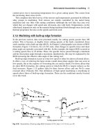
Initial Alignment Check
It is necessary to first obtain a complete set of indicator readings with the
machines at ambient temperature, or non-operating condition. Figure 7.19
shows a hypothetical set of readings (i.e., top or 12 o’clock, right or 3 o’clock,
bottom or 6 o’clock, and left or 9 o’clock) taken for the stationary machine shaft
‘‘A’’ and the movable shaft ‘‘B.’’ The following is the procedure to be followed
for obtaining these readings.
The indicator bar either must be free of sags or compensated for in the
readings.
Figure 7.19 Hypothetical present state, or actual, dial-indicator readings.
Keith Mobley /Maintenance Fundamentals Final Proof 15.6.2004 4:57pm page 95
Shaft Alignment 95
Check the coupling for concentricity. If not concentric, replace the
coupling.
Zero the dial at top of the coupling.
Record the readings at 90-degree increments taken clockwise as indi-
cated in Figure 7.19.
For any reading on a shaft, the algebraic sum of the left and right (9 and
3 o’clock) must equal the top and bottom (12 and 6 o’clock). The
calculations below are for the example illustrated in Figure 7.19,
in which shafts A and B are out of alignment as illustrated by
the difference in the sums of the (L þR) readings for shafts A
and B and the difference in the sums of the (T þ B) readings for A and B.
Shaft A: Shaft B:
L
1
þ R
1
¼þ12 þ ( þ24) ¼þ36 L
2
þ R
2
¼À26 þ ( À22) ¼À48
T
1
þ B
1
¼ 0 þ( þ36) ¼þ36 T
2
þ B
2
¼ 0 þ( À48) ¼À48
Note, however, that this difference, which represents the amount of
misalignment at the coupling, is not the amount of correction needed
to be performed at the machine feet. This must be determined by using
rise-and-run concepts.
The dial indicator should start at midrange and not exceed the total
range. In other words, do not peg the indicator. If misalignment
exceeds the indicator span, it will be necessary to roughly align the
machine before proceeding.
Determining Corrections or Amount of Shim
With horizontally mounted units, it is possible to correct both angularity and
offset with one adjustment. To compute the adjustments needed to achieve the
desired alignment, it is necessary to establish three horizontal measurements.
These measurements are critical to the success of any alignment and must be
accurate to within
1
⁄
16
inch (see Figure 7.20). Again, the procedure described here
is for the reverse-dial indicator method (see Figure 7.16).
1. Determine the distance, D
1
, between the dial indicators.
2. It is also necessary to know the distance from the indicator plane of
the stationary machine, or Machine ‘‘A,’’ to the near adjustment
plane of the MTBM, or Machine ‘‘B.’’ This is the distance between
the indicator planes of Machine ‘‘A’’ to the near foot (N
f
) of Machine
‘‘B’’ and is referred to as D
2
.
3. The distance between the indicator plane of Machine ‘‘A’’ to the far
adjustment plane is needed. This distance is referred to as D
3
and is
the distance between the indicator plane of Machine ‘‘A’’ to the far
foot (F
f
) of Machine ‘‘B.’’
Keith Mobley /Maintenance Fundamentals Final Proof 15.6.2004 4:57pm page 96
96 Maintenance Fundamentals
The vertical and horizontal adjustments necessary to move Machine ‘‘B’’ from
the actual position (Figure 7.19 readings) to the desired state of alignment
(Figure 7.21 readings) are determined by using the equations below. Note that
the desired state of alignment is obtained from manufacturer’s tolerances. (When
using manufacturer’s tolerances, it is important to know if they compensate for
thermal growth.)
For example, the shim adjustment at the near foot (N
f
) and far foot (F
f
) for the
readings in Figures 7.19 and 7.21 can be determined by using the vertical
movement formulas shown below. Since the top readings equal zero, only the
bottom readings are needed in the calculation.
Indicator
Machine “A” Machine “B”
Machine “B”
Movable
Machine “A”
Stationary
8”
123
4
12”
24”
D
1
D
2
D
3
Planes Mounting Feet
Centerline
Figure 7.20 Reverse-dial indicator alignment setup.
Figure 7.21 Desired dial indicator state readings at ambient conditions.
Keith Mobley /Maintenance Fundamentals Final Proof 15.6.2004 4:57pm page 97
Shaft Alignment 97
V
1
¼
B
3
À B
1
2
¼
( À 10) À( þ36)
2
¼À23
V
2
¼
B
4
À B
2
2
þ V
1
¼
( þ 20) À( À48)
2
þ ( À23) ¼þ11
N
f
¼
V
2
 D
2
D
1
À V
1
¼
( þ 11) Â( þ12)
8
À ( À23) ¼þ40
F
f
¼
V
2
 D
3
D
1
À V
1
¼
( þ 11) Â( þ24)
8
À ( À23) ¼þ56
For N
f
, at near foot of ‘‘B,’’ add 0.040-inch (40 mil) shims. For F
f
, at the far foot
of ‘‘B,’’ add 0.056-inch (56 mil) shims.
For example, the side-to-side movement at N
f
and F
f
can be determined in the
horizontal movement formula:
H
1
¼
(R
3
À L
3
) À (R
1
À L
1
)
2
¼
[( À 15) À( þ5)] À [( þ 24) À ( þ12)]
2
¼À16
H
2
¼
(R
4
À L
4
) À (R
2
À L
2
)
2
þ H
1
¼
[( þ 6) À( þ14)] À [( À 22) À ( À26)]
2
þ ( À16) ¼À22
N
f
¼
H
2
 D
2
D
1
À H
1
¼
( À 22) Â( þ12)
8
À ( À16) ¼À17
F
f
¼
H
2
 D
3
D
1
À H
1
¼
( À 22) Â( þ24)
8
À ( À16) ¼À50
For N
f
, at near foot of ‘‘B,’’ move right 0.017 inch.
For F
f
, at far foot of ‘‘B,’’ move right 0.050 inch.
Vertical Units
The alignment process for most vertical units is quite different from that used for
aligning horizontally mounted units. The major reason is that most vertical units
are not designed to allow realignment to be performed under the assumption that
they will always fit together perfectly. Field checks, however, have proven this
assumption to be wrong in a vast majority of cases. Although it is quite difficult
to correct misalignment on a vertical unit, it is essential that it be done to
increase reliability and decrease maintenance costs.
Keith Mobley /Maintenance Fundamentals Final Proof 15.6.2004 4:57pm page 98
98 Maintenance Fundamentals
Initial Alignment Check
The following procedure can be used on vertical units to obtain angularity and
offset values needed to compare with recommended manufacturer’s (i.e., desired)
tolerances to determine if a unit is out of alignment.
Perform an alignment check on the unit by using the reverse-dial
indicator method.
Install brackets and dial indicators as illustrated in Figure 7.22.
Check the alignment in two planes by using the following directional
designators: ‘‘north/south’’ and ‘‘east/west.’’
Consider the point of reference nearest to you as being ‘‘south,’’ which corres-
ponds to the ‘‘bottom’’ position of a horizontal unit. (Note: Indicator sag does
not occur when readings are taken as indicated below.)
Perform the ‘‘north/south’’ alignment checks by setting the indicator
dials to ‘‘zero’’ on the ‘‘north’’ side and take the readings on the
‘‘south’’ side.
Perform the ‘‘east/west’’ alignment checks by setting the indicator dials
to ‘‘zero’’ on the ‘‘west’’ side and take the readings on the ‘‘east’’ side.
Record the distance between the dial indicator centerlines, D
1
.
Record the distance from the centerline of the coupling to the top dial
indicator.
DIAL INDICATOR “B”
DISTANCE FROM
COUPLING TO
DIAL INDICATOR
BRACKET (TYP) IMS 1984
PUMP SHAFT
MOTOR SHAFT
BASE PLATE
MOTOR FLANGE
MOTOR
MOTOR
EAST
WEST
DISTANCE
BETWEEN
INDICATOR
READINGS
NORTH
SOUTH
TOP VIEW
SIDE VIEW
DIAL INDICATORS
(FOR RIM READINGS)
FLEXIBLE COUPLING
DIAL INDICATOR “A”
C
L
C
L
Figure 7.22 Proper dial indicator and bracket positioning when performing a vertical
pump alignment.
Keith Mobley /Maintenance Fundamentals Final Proof 15.6.2004 4:57pm page 99
Shaft Alignment 99
Record ‘‘zero’’ for the distance, D
2
, from the Indicator A to the ‘‘top
foot’’ of the movable unit.
Record the distance, D
3
, from Indicator A to the ‘‘bottom foot’’ of the
movable unit.
Set the top dial indicator to ‘‘zero’’ when it is in the ‘‘north’’ position.
North/South Alignment Check
Rotate shafts 180 degrees until the top indicator is in the ‘‘south’’
position and obtain a reading.
Rotate shafts 180 degrees again and check for repeatability of ‘‘zero’’
on the ‘‘north’’ side, then another 180 degrees to check for repeatability
of reading obtained on the ‘‘south’’ side.
Note: If results are not repeatable, check bracket and indicators for
looseness and correct as necessary. If repeatable, record the ‘‘south’’
reading.
Rotate the shafts until the bottom dial indicator is in the ‘‘north’’
position and set it to ‘‘zero.’’
Rotate the shafts 180 degrees and record ‘‘south’’ side reading. Check
for repeatability.
East/West Alignment Check
Rotate the shafts until the top dial indicator is in the ‘‘west’’ position
and set it to ‘‘zero.’’
Rotate the shafts 180 degrees and obtain the reading on the ‘‘east’’ side.
Check for repeatability.
Rotate the shafts until the bottom dial indicator is in the ‘‘west’’
position and set it to ‘‘zero.’’
Rotate the shafts 180 degrees and again obtain the reading on the
‘‘east’’ side. Check for repeatability.
Determining Corrections
If the unit must be realigned, with vertical units it is necessary to use the rim-and-
face method to obtain offset and angularity readings. Unlike horizontally
mounted units, it is not possible to correct both angularity and offset with one
adjustment. Instead, we must first correct the angular misalignment in the unit by
shimming and then correct the offset byproperly positioning the motor base flange
on the base plate.
Because most units are designed in such a manner that realignment is not
intended, it is necessary to change this design feature. Specifically, the ‘‘rabbet
fit’’ between the motor flange and the base plate is the major hindrance to
realignment.
Keith Mobley /Maintenance Fundamentals Final Proof 15.6.2004 4:57pm page 100
100 Maintenance Fundamentals
Therefore, before proceeding with the alignment method, one should consider
that the rabbet fit is designed to automatically ‘‘center’’ the motor during instal-
lation. In theory, this should create a condition of perfect alignment between the
motor and the driven-unit shafts. The rabbet fit is not designed to support the
weight of the unit or resist the torque during start-up or operation; the motor
flange and hold-down bolts are designed to do this. Since the rabbet fit is merely
a positioning device, it is quite permissible to ‘‘bypass’’ it. This may be accom-
plished by either of the following:
Machining off the entire male portion
Grinding off the male and/or female parts as necessary.
Angularity Correction
There are three steps to follow when correcting for angularity. The first step is to
obtain initial readings. The next step is to obtain corrected readings. The third
step is to shim the machine.
Step 1: Initial Readings The following procedure is for obtaining initial readings.
Change the position of the bottom dial indicator so that it can obtain
the ‘‘face readings’’ of the lower bracket (see Figure 7.23).
MOTOR SHAFT
DIAL INDICATOR "B"
(FOR FACE READINGS)
USED FOR ANGULARITY
CORRECTION
"X"=BOLT CIRCLE RADIUS
"Y"=RADIUS OF DIAL INDICATOR TRAVEL
FLEXIBLE COUPLING
PUMP SHAFT
USED FOR OFFSET CORRECTION
DIAL INDICATOR "A"
(FOR RIM READINGS)
HOLD-DOWN BOLT (TYP)
SHAFT
MACHINE BASE
MOUNTING FLANGE
"X"
"Y"
C
L
C
L
Figure 7.23 Bottom dial indicator in position to obtain ‘‘face readings.’’
Keith Mobley /Maintenance Fundamentals Final Proof 15.6.2004 4:57pm page 101
Shaft Alignment 101
Looking from the ‘‘south’’ side, identify the hold-down bolt at the
‘‘north’’ position and label it #1. Proceeding clockwise, number each
hold-down bolt until all are numbered (see Figure 7.24).
Determine the largest negative reading, which occurs at the widest
point, by setting the bottom dial indicator to ‘‘zero’’ at point #1.
This should be in line with centerline of hold-down bolt #1. Record
the reading.
Turn the shafts in a clockwise direction and record the data at each
hold-down bolt centerline until readings have been taken at all
positions.
Use Figure 7.25 as an example of how the readings are taken. Remem-
ber that all readings are taken from the position of looking down on
the lower bracket.
Note: We will always be looking for the largest negative (À) reading. If all
readings are positive (þ), the initial set point of zero will be considered the
largest negative (À) reading. In Figure 7.25, the largest negative reading occurs
at point #7.
Step 2: Corrected Readings Obtain corrected readings with the following
procedure.
Rotate the shafts until the indicator is again at the point where the
largest negative reading occurs.
Base Plate
MOTOR FLANGE
BRACKET
DIAL INDICATOR
SHAFTS
HOLD-DOWN BOLT
NOTE: DIAL INDICATOR “B” WILL BE SET UP FOR TAKING FACE READINGS
OFF OF THE LOWER BRACKET (AS INDICATED BY ). READINGS WILL THEN
BE TAKEN AT POSITIONS INDICATED BY .
1
2
4
Figure 7.24 Diagram of a base plate with hold-down bolts numbered.
Keith Mobley /Maintenance Fundamentals Final Proof 15.6.2004 4:57pm page 102
102 Maintenance Fundamentals
Set the dial indicator to ‘‘zero’’ at this point and take another complete
set of readings. With Figure 7.25 as an example, set the dial indicator
to ‘‘zero’’ at point #7 (in line with centerline of bolt #7). The results of
readings at the other hold-down bolt centerlines are as follows:
#1 þ16
#2 þ23
#3 þ32
#4 þ24
#5 þ17
#6 þ8
#7 0
#8 þ7
Step 3: Shimming Perform shimming with the following procedure. Measure the
hold-down bolt circle radius and the radius of dial indicator travel as shown in
Figure 7.26.
Compute the shim multiplier, X/Y, where:
X ¼ Bolt circle radius
Y ¼ Radius of indicator travel
1st READING {0}
{SET INDICATOR TO
-
0
-
}
1
2
3
4
5
6
8
7
1
2
3
4
5
6
8
7
1
2
3
4
5
6
8
7
1
2
3
4
5
6
8
7
1
2
3
4
5
6
8
7
1
2
3
4
5
6
8
7
1
2
3
4
5
6
8
7
1
2
3
4
5
6
8
7
2nd READING {+7}
5th READING {+1} 6th READING {−8} 7th READING {−16} 8th READING {−9}
3rd READING {+16} 4th READING {+8}
Figure 7.25 Determining the largest negative reading and the widest point.
Keith Mobley /Maintenance Fundamentals Final Proof 15.6.2004 4:57pm page 103
Shaft Alignment 103
For example: If X ¼ 9 inches and Y ¼ 4 inches, the shim multiplier is 9/4 ¼ 2.25.
The necessary shimming at each bolt equals the shim multiplier (2.25) times the
bolt’s corrected reading as determined in Chapter 4.
#1 – 2:25 Â16 ¼ 36 mils ¼ 0:036 inch
#2 – 2:25 Â23 ¼ 52 mils ¼ 0:052 inch
#3 – 2:25 Â32 ¼ 72 mils ¼ 0:072 inch
#4 – 2:25 Â24 ¼ 54 mils ¼ 0:054 inch
#5 – 2:25 Â17 ¼ 38 mils ¼ 0:038 inch
#6 – 2:25 Â8 ¼ 18 mils ¼ 0:018 inch
#7 – 2:25 Â0 ¼ 0 mils ¼ 0:000 inch
#8 – 2:25 Â7 ¼ 16 mils ¼ 0:016 inch
Offset Correction Once the angularity has been corrected by making the neces-
sary shim adjustments at each of the hold-down bolts, it is necessary to correct
the offset by sliding the movable unit (i.e., motor in this example) on the base
plate. The top dial indicator is used to monitor the movements as they are being
made. ‘‘North/south’’ and ‘‘east/west’’ designations are used to describe the
positioning of the unit.
North// South Correction The following is the procedure for making the ‘‘north/
south’’ corrections.
MOTOR SHAFT
DIAL INDICATOR “B”
“X” = BOLT CIRCLE RADIUS “Y” = RADIUS OF DIAL INDICATOR TRAVEL
(FOR FACE READINGS)
SHAFT
HOLD - DOWN BOLT (TYP)
MOUNTING FLANGE
MACHINE BASE
DIAL INDICATOR “A”
(FOR RIM READINGS)
FLEXIBLE COUPLING
PUMP SHAFT
“Y”
“x”
Figure 7.26 Determining bolt circle radius and radius of dial indicator.
Keith Mobley /Maintenance Fundamentals Final Proof 15.6.2004 4:57pm page 104
104 Maintenance Fundamentals
Rotate shafts until the top dial indicator is in the ‘‘north’’ position. Set it
to ‘‘zero.’’
Rotate the shafts 180 degrees (until the top dial indicator is in the
‘‘south’’ position) and record the reading.
Determine movement necessary to correct the offset in this plane by
dividing the reading by 2. This is the amount of movement (in mils)
required. Direction of movement can be determined by the following
rule: If the sign of the reading is positive (þ), the motor must be moved
toward the ‘‘north.’’ If negative (À), it must be moved toward the
‘‘south.’’
East/West Correction The following is the procedure for making the ‘‘east/west’’
corrections.
Rotate the shafts until the top dial indicator is in the ‘‘west’’ position.
Set it to ‘‘zero.’’
Rotate the shafts 180 degrees (until the top dial indicator is in the
‘‘east’’ position) and record the reading.
Determine movement necessary to correct the offset in this plane by
dividing the reading by 2. This value will be the amount of movement
(in mils) required. Direction of movement can be determined by the
following rule: If the sign of the reading is positive (þ), the movable
unit (motor) must be moved toward the ‘‘west.’’ If negative (À), it must
be moved toward the ‘‘east.’’
Making the Offset Corrections After the amounts and directions of required
offset adjustments have been obtained, the next step is to actually align the
equipment. This is accomplished by using two dial indicators with magnetic
bases, which are installed on the south (or north) and west (or east) sides of
the mounting flange of the movable unit or motor. See Figure 7.27 for an
illustration of this setup. It is important to zero both dial indicators before
making adjustments and to watch both dial indicators while moving the unit.
Note: The motor position on the base plate must be adjusted to align the
equipment, which may require machining or grinding of the rabbet fit. Remem-
ber, however, that the rabbet fit is only a positioning device and is not a
structural support.
COMPUTATIONS,ADJUSTMENTS, AND PLOTS
Once initial alignment readings are obtained by using the preceding procedures,
they must be adjusted for changes in the machine-train, which can be caused by
process movement, vibration, or thermal growth. These adjustments must be
Keith Mobley /Maintenance Fundamentals Final Proof 15.6.2004 4:57pm page 105
Shaft Alignment 105
made to achieve proper alignment at normal operating conditions. Once read-
ings are obtained, the use of graphical plotting helps the technician visualize
misalignment and the necessary corrections that must be made and to catch
computation errors.
Adjustments for Thermal Growth
Thermal growth generally refers to the expansion of materials with increasing
temperature. For alignment purposes, thermal growth is the shaft centerline
movement associated with the change in temperature from the alignment
process, which is generally performed at ambient conditions, to normal operat-
ing conditions. Such a temperature difference causes the elevation of one or both
shafts to change and misalignment to result. Temperature changes after align-
ment produce changes that may affect both offset and angularity of the shafts
and can be in the vertical plane, horizontal plane, or any combination.
Proper alignment practices, therefore, must compensate for thermal growth.
In effect, the shafts must be misaligned in the ambient condition so they will
become aligned when machine temperatures reach their normal operating range.
Generally, manufacturers supply dial indicator readings at ambient conditions,
which compensate for thermal movement and result in colinear alignment at
MOUNTING BOLT
MOUNTING FLANGE
PLACEMENT OF DIAL INDICATORS TO MONITOR
CORRECTION OF “OFFSET”
SOUTH
MOTOR
DIAL INDICATORS SHOULD
BE PLACED AGAINST THE
BASE OF THE MOTOR FLANGE
TO MONITOR THE MOVEMENT
IN BOTH NORTH/SOUTH &
EAST/WEST PLANES WHILE
MAKING OFFSET CORRECTIONS.
Figure 7.27 Placement of dial indicators to monitor offset corrections.
Keith Mobley /Maintenance Fundamentals Final Proof 15.6.2004 4:57pm page 106
106 Maintenance Fundamentals
normal service conditions. When thermal rise information is supplied by the
manufacturer or from machine history records, the necessary compensation may
be made during the initial alignment procedure.
However, information concerning thermal rise is not available for all equipment.
Generally, manufacturers of critical machinery, such as centrifugal air compres-
sors and turbines, will include information relating to thermal rise in their instal-
lation manuals in the section dealing with alignment. When this information is not
available, the only method to determine the exact amount of compensation
necessary to correct for thermal rise is referred to as a ‘‘hot alignment check.’’
Thermal Compensation Targets
A simple procedure for determining thermal compensation targets is to calculate
the movement of the shaft due to temperature change at the bearings or feet.
Note that calculated thermal growth is highly dependent on the accuracy of the
temperature assumptions and is useful only for initial alignment estimates.
Therefore the targets developed from the following procedure should be revised
when better data become available.
The formula for this calculation is very simple and very accurate. It requires
three factors: (1) the difference in temperature of the machine housing between
the feet and shaft bearings, (2) the distance between the shaft centerline and the
feet, and (3) the coefficient of thermal expansion of the machine housing mater-
ial. The thermal growth between any two points of any metal can be predicted by
the formula:
Growth ¼ DT ÂL ÂC
Where:
DT ¼ Temperature difference between the feet and shaft bearings, 8F
L ¼ Length between points (often the vertical distance from the shim plane to
the shaft centerline), inches
C ¼ Growth factor (coefficient of thermal expansion)
Growth factors (mils/inch/8F) for common materials are:
Aluminum 0.0126
Bronze 0.0100
Cast Iron, Gray 0.0059
Stainless Steel 0.0074
Mild Steel, Ductile Iron 0.0063
Note: The thermal growth formula is usually applied only to the vertical com-
ponents of the machine. While the formula can be applied to horizontal growth,
this direction is often ignored.
Keith Mobley /Maintenance Fundamentals Final Proof 15.6.2004 4:57pm page 107
Shaft Alignment 107
For vertical growth, L is usually taken as the vertical height from the bottom of
the foot where shims touch the machine to the shaft centerline. In the case where
the machine is mounted on a base that has significant temperature variations
along its length, L is the vertical distance from the concrete or other constant
temperature baseline to the shaft centerline.
Hot Alignment Check
A hot alignment check is performed exactly like an ambient alignment check (see
Chapter 4) with the added safety precautions required for hot machinery. The
accuracy of a hot alignment check depends on how soon after shutdown dial
indicator readings can be taken. Readings may be taken within a few minutes
with the use of shaft-mounted brackets that span a flexible coupling. To speed up
the process, assemble the brackets to the fullest extent possible prior to shutdown
so that they need only be bolted to the shafts once the machine stops rotating.
Adjustments for Sag and Soft-Foot
The procedure for making adjustments to the readings to account for indicator
sag is presented in Chapter 2.
Graphical Plotting
The graphical plotting technique for computing initial alignment can be per-
formed with any of the three types of measurement fixtures (i.e., reverse-dial
indicator, rim-and-face, or optical). The following steps should be followed when
plotting alignment problems:
1. Determine the following dimensions from the machine-train, which
are illustrated in Figure 7.28:
Figure 7.28 Graphical plotting measurements.
Keith Mobley /Maintenance Fundamentals Final Proof 15.6.2004 4:57pm page 108
108 Maintenance Fundamentals
FB
S
¼ Front-foot to back-foot of stationary train component
CF
S
¼ Front-foot to coupling of stationary train component
CF
M
¼ Coupling to front-foot of movable train component
FB
M
¼ Front-foot to back-foot of movable train component
CD ¼ Coupling or working diameter
2. On graph or grid paper, pick a horizontal line to be used as the
baseline (also referred to as reference line or zero-line). This line
usually crosses the center of the page from left to right and represents
the rotational centerline of the stationary machine-train component.
3. Determine the number of inches or mils that each block on the graph
paper represents by first finding the distance from the back-foot of the
stationary component to the back-foot of the movable component.
Then determine the inches or mils per square that will spread the
entire machine-train across the graph paper.
4. Plot inches or mils horizontally from left to right.
5. Plot mils from top to bottom vertically. As a general rule, assign 0.5,
1, 2, 5, 10 mils to each vertical step. Note that this scale may need to
be changed in cases where excessive misalignment is present.
Known Foot Correction Values
The following steps should be followed to plot misalignment when foot correc-
tion values are known (see Figure 7.29):
1. On the baseline, start at the left end and mark the stationary back-
foot. From the back-foot and moving right, count the number of
+2.0
+1.0
+0.5
+0.5
Mils
+1.0
+2.0
+50
+5.0
5 10152025
Inches
30 35 40 45 50 55 60 65
FF
s
1
3
4
6
5
3
FF
M
FB
M
2
FB
s
CF
s
Figure 7.29 Graphical plotting of known foot correction.
Keith Mobley /Maintenance Fundamentals Final Proof 15.6.2004 4:57pm page 109
Shaft Alignment 109
squares along the baseline corresponding to FF
S
. Mark the stationary
front-foot location.
2. Starting at the stationary front-foot and moving right, count the
number of squares along the baseline corresponding to CF
S
and
mark the coupling location.
3. Continue this process until the entire machine-train is indicated on the
graph.
4. To plot misalignment, locate the CF
S
or coupling on the horizontal
baseline. From that point, count up or down on the vertical axis until
the amount of offset is located on the mils scale. Mark this point on
the graph. Use care to ensure that the location is accurately located.
Positive values should be above the horizontal baseline and negative
values below the line.
5. Locate the FB
M
or back-foot of the movable component. Move either
up or down vertically on the scale to the point of the offset measure-
ment. Mark this point on the graph. Remember, positive values are
above the horizontal baseline and negative values below the line.
6. Draw a line from the back-foot (FB
M
) of the movable component or
MTBM through the front-foot of the movable component toward
the vertical line where the stationary coupling is located. Draw a
short vertical line at the coupling end of the line. Finish the MTBM
by drawing little squares to represent the feet, darkening the line from
the back-foot to coupling, and darkening the coupling line.
Known Coupling Results
When plotting coupling misalignment, use the following steps instead of those
from the preceding section (see Figure 7.30).
+2.0
+1.0
+0.5
-
0.5
Mils
-
1.0
-
2.0
+50
-
5.0
5 10152025
Inches
30 35 40 50 55 60 65
FB
M
FB
M
6
CD
4
4
5
2
3
1
CF
s
Figure 7.30 Graphical plotting of known coupling results.
Keith Mobley /Maintenance Fundamentals Final Proof 15.6.2004 4:57pm page 110
110 Maintenance Fundamentals
1. Start at the stationary coupling location and, moving up or down the
vertical axis (mils), count the number of squares corresponding to the
vertical or horizontal offset. Move up for positive offset and down for
negative offset. Mark a point, which is the MTBM coupling location.
2. Start at the MTBM coupling center and, moving right on the hori-
zontal line, count the number of squares corresponding to the CD
dimension (see Figure 7.28) and lightly mark the point. From this
point, move up or down vertically on the mils scale the number of
squares corresponding to the total mils of angularity per diameter
(CD) and mark lightly.
3. From the MTBM coupling center, draw a line through the point
marked in the preceding step and extending past the MTBM back-
feet location. This line is the MTBM centerline.
4. Now place the MTBM feet. Starting at the MTBM coupling and
moving right along a horizontal line, count the number of squares
corresponding to CF
M
(see Figure 7.28). Then move straight vertically
to the MTBM centerline and mark the location of the front-foot.
Then starting at the MTBM front-foot and moving right, count the
number of squares corresponding to FB
M
. From this point, move
vertically to the MTBM centerline and mark the location of the
MTBM back-foot.
5. Draw a short line perpendicular to the shaft centerline to mark the
MTBM coupling. Finish the MTBM by drawing little squares to
represent the feet and darkening the line from the back-foot to the
coupling.
6. Correction of the MTBM machine-train component can now be
measured directly from the graph. Locate the appropriate MTBM
foot location and read the actual correction from the vertical or mils
scale.
Keith Mobley /Maintenance Fundamentals Final Proof 15.6.2004 4:57pm page 111
Shaft Alignment 111
8
ROTOR BALANCING
Mechanical imbalance is one of the most common causes of machinery vibration
and is present to some degree on nearly all machines that have rotating parts
or rotors. Static, or standing, imbalance is the condition in which there is
more weight on one side of a centerline than the other. However, a rotor may
be in perfect static balance and not be in a balanced state when rotating at
high speed.
If the rotor is a thin disc, careful static balancing may be accurate enough for
high speeds. However, if the rotating part is long in proportion to its diameter,
and the unbalanced portions are at opposite ends or in different planes, the
balancing must counteract the centrifugal force of these heavy parts when they
are rotating rapidly.
This section provides information needed to understand and solve the majority
of balancing problems by using a vibration/balance analyzer, a portable device
that detects the level of imbalance, misalignment, etc., in a rotating part based on
the measurement of vibration signals.
SOURCES OF VIBRATION CAUSED BY MECHANICAL IMBALANCE
Two major sources of vibration caused by mechanical imbalance in equipment
with rotating parts or rotors are (1) assembly errors and (2) incorrect key length
guesses during balancing.
Keith Mobley /Maintenance Fundamentals Final Proof 15.6.2004 7:32pm page 112
112
Assembly Errors
Even when parts are precision balanced to extremely close tolerances, vibration
caused by mechanical imbalance can be much greater than necessary because of
assembly errors. Potential errors include relative placement of each part’s center
of rotation, location of the shaft relative to the bore, and cocked rotors.
Center of Rotation
Assembly errors are not simply the additive effects of tolerances but also include
the relative placement of each part’s center of rotation. For example, a ‘‘per-
fectly’’ balanced blower rotor can be assembled to a ‘‘perfectly’’ balanced shaft
and yet the resultant imbalance can be high. This can happen if the rotor is
balanced on a balancing shaft that fits the rotor bore within 0.5 mils (0.5
thousandths of an inch) and then is mounted on a standard cold-rolled steel
shaft allowing a clearance of over 2 mils.
Shifting any rotor from the rotational center on which it was balanced to the
piece of machinery on which it is intended to operate can cause an assembly
imbalance four to five times greater than that resulting simply from tolerances.
For this reason, all rotors should be balanced on a shaft having a diameter as
nearly the same as possible as the shaft on which it will be assembled.
For best results, balance the rotor on its own shaft rather than on a balancing
shaft. This may require some rotors to be balanced in an overhung position, a
procedure the balancing shop often wishes to avoid. However, it is better to use
this technique rather than being forced to make too many balancing shafts. The
extra precision balance attained by using this procedure is well worth the effort.
Method of Locating Position of Shaft Relative to Bore
Imbalance often results with rotors that do not incorporate setscrews to locate
the shaft relative to the bore (e.g., rotors that are end-clamped). In this case, the
balancing shaft is usually horizontal. When the operator slides the rotor on the
shaft, gravity causes the rotor’s bore to make contact at the 12 o’clock position
on the top surface of the shaft. In this position, the rotor is end-clamped in place
and then balanced.
If the operator removes the rotor from the balancing shaft without marking the
point of bore and shaft contact, it may not be in the same position when
reassembled. This often shifts the rotor by several mils as compared with the
axis on which it was balanced, thus causing an imbalance to be introduced. The
vibration that results is usually enough to spoil what should have been a
Keith Mobley /Maintenance Fundamentals Final Proof 15.6.2004 7:32pm page 113
Rotor Balancing 113