Maintenance Fundamentals Episode 1 part 7 ppt
Bạn đang xem bản rút gọn của tài liệu. Xem và tải ngay bản đầy đủ của tài liệu tại đây (159.55 KB, 20 trang )
precision balance and produce a barely acceptable vibration level. In addition, if
the resultant vibration is resonant with some part of the machine or structure, a
more serious vibration could result.
To prevent this type of error, the balancer operators and those who do final
assembly should follow the following procedure. The balancer operator should
permanently mark the location of the contact point between the bore and the
shaft during balancing. When the equipment is reassembled in the plant or
the shop, the assembler should also use this mark. For end-clamped rotors, the
assembler should slide the bore on the horizontal shaft, rotating both until
the mark is at the 12 o’clock position, and then clamp it in place.
Cocked Rotor
If a rotor is cocked on a shaft in a position different from the one in which it was
originally balanced, an imbalanced assembly will result. If, for example, a pulley
has a wide face that requires more than one setscrew, it could be mounted on-
center but be cocked in a different position than during balancing. This can
happen by reversing the order in which the setscrews are tightened against a
straight key during final mounting as compared with the order in which the
setscrews were tightened on the balancing arbor. This can introduce a pure
couple imbalance, which adds to the small couple imbalance already existing in
the rotor and causes unnecessary vibration.
For very narrow rotors (i.e., disc-shaped pump impellers or pulleys), the distance
between the centrifugal forces of each half may be very small. Nevertheless, a
very high centrifugal force, which is mostly counterbalanced statically by
its counterpart in the other half of the rotor, can result. If the rotor is slightly
cocked, the small axial distance between the two very large centrifugal forces
causes an appreciable couple imbalance, which is often several times the allow-
able tolerance. This is because of the fact that the centrifugal force is propor-
tional to half the rotor weight (at any one time, half of the rotor is pulling against
the other half) times the radial distance from the axis of rotation to the center of
gravity of that half.
To prevent this, the assembler should tighten each setscrew gradually—first one,
then the other, and back again—so that the rotor is aligned evenly. On flange-
mounted rotors such as flywheels, it is important to clean the mating surfaces
and the bolt holes. Clean bolt holes are important because high couple imbalance
can result from the assembly bolt pushing a small amount of dirt between the
surfaces, cocking the rotor. Burrs on bolt holes also can produce the same
problem.
Keith Mobley /Maintenance Fundamentals Final Proof 15.6.2004 7:32pm page 114
114 Maintenance Fundamentals
Other
Other assembly errors can cause vibration. Variances in bolt weights when one
bolt is replaced by one of a different length or material can cause vibration. For
setscrews that are 90 degrees apart, the tightening sequence may not be the same
at final assembly as during balancing. To prevent this, the balancer operator
should mark which was tightened first.
Key Length
With a keyed-shaft rotor, the balancing process can introduce machine vibration
if the assumed key length is different from the length of the one used during
operation. Such an imbalance usually results in a mediocre or ‘‘good’’ running
machine as opposed to a very smooth running machine.
For example, a ‘‘good’’ vibration level that can be obtained without following
the precautions described in this section is amplitude of 0.12 in./sec (3.0 mm/sec).
By following the precautions, the orbit can be reduced to about 0.04 in./sec
(1 mm/sec). This smaller orbit results in longer bearing or seal life, which is
worth the effort required to make sure that the proper key length is used.
When balancing a keyed-shaft rotor, one half of the key’s weight is assumed to
be part of the shaft’s male portion. The other half is considered to be part of the
female portion that is coupled to it. However, when the two rotor parts are sent
to a balancing shop for rebalancing, the actual key is rarely included. As a result,
the balance operator usually guesses at the key’s length, makes up a half key, and
then balances the part. (Note: A ‘‘half key’’ is of full-key length but only half-key
depth.)
To prevent an imbalance from occurring, do not allow the balance operator to
guess the key length. It is strongly suggested that the actual key length be
recorded on a tag that is attached to the rotor to be balanced. The tag should
be attached in such a way that another device (such as a coupling half, pulley,
fan, etc.) cannot be attached until the balance operator removes the tag.
THEORY OF IMBALAN CE
Imbalance is the condition in which there is more weight on one side of a
centerline than on the other. This condition results in unnecessary vibration,
which generally can be corrected by the addition of counterweights. There are
four types of imbalance: (1) static, (2) dynamic, (3) couple, and (4) dynamic
imbalance combinations of static and couple.
Keith Mobley /Maintenance Fundamentals Final Proof 15.6.2004 7:32pm page 115
Rotor Balancing 115
Static
Static imbalance is single-plane imbalance acting through the center of gravity of
the rotor, perpendicular to the shaft axis. The imbalance also can be separated
into two separate single-plane imbalances, each acting in-phase or at the same
angular relationship to each other (i.e., 0 degrees apart). However, the net effect
is as if one force is acting through the center of gravity. For a uniform straight
cylinder such as a simple paper machine roll or a multi-grooved sheave, the
forces of static imbalance measured at each end of the rotor are equal in
magnitude (i.e., the ounce-inches or gram-centimeters in one plane are equal to
the ounce-inches or gram-centimeters in the other).
In static imbalance, the only force involved is weight. For example, assume that a
rotor is perfectly balanced and therefore will not vibrate regardless of the speed
of rotation. Also assume that this rotor is placed on frictionless rollers or ‘‘knife
edges.’’ If a weight is applied on the rim at the center of gravity line between two
ends, the weighted portion immediately rolls to the 6 o’clock position because of
the gravitational force.
When rotation occurs, static imbalance translates into a centrifugal force. As a
result, this type of imbalance is sometimes referred to as ‘‘force imbalance,’’ and
some balancing machine manufacturers use the word ‘‘force’’ instead of ‘‘static’’
on their machines. However, when the term ‘‘force imbalance’’ was just starting
to be accepted as the proper term, an American standardization committee on
balancing terminology standardized the term ‘‘static’’ instead of ‘‘force.’’ The
rationale was that the role of the standardization committee was not to deter-
mine and/or correct right or wrong practices but to standardize those currently in
use by industry. As a result, the term ‘‘static imbalance’’ is now widely accepted
as the international standard and therefore is the term used in this document.
Dynamic
Dynamic imbalance is any imbalance resolved to at least two correction planes
(i.e., planes in which a balancing correction is made by adding or removing
weight). The imbalance in each of these two planes may be the result of many
imbalances in many planes, but the final effects can be characterized to only two
planes in almost all situations.
An example of a case in which more than two planes are required is flexible
rotors (i.e., long rotors running at high speeds). High speeds are considered to be
revolutions per minute (rpm) higher than about 80% of the rotor’s first critical
speed. However, in over 95% of all run-of-the-mill rotors (e.g., pump impellers,
armatures, generators, fans, couplings, pulleys, etc.), two-plane dynamic balance
Keith Mobley /Maintenance Fundamentals Final Proof 15.6.2004 7:32pm page 116
116 Maintenance Fundamentals
is sufficient. Therefore, flexible rotors are not covered in this document because
of the low number in operation and the fact that specially trained people at the
manufacturer’s plant almost always perform balancing operations.
In dynamic imbalance, the two imbalances do not have to be equal in magnitude to
each other, nor do they have to have any particular angular reference to each other.
For example, they could be 0 (in-phase), 10, 80, or 180 degrees from each other.
Although the definition of dynamic imbalance covers all two-plane situations, an
understanding of the components of dynamic imbalance is needed so that its
causes can be understood. Also, an understanding of the components makes it
easier to understand why certain types of balancing do not always work with many
older balancing machines for overhung rotors and very narrow rotors. The pri-
mary components of dynamic imbalance include the number of points of imbal-
ance, the amount of imbalance, the phase relationships, and the rotor speed.
Points of Imbalance
The first consideration of dynamic balancing is the number of imbalance points
on the rotor, as there can be more than one point of imbalance within a rotor
assembly. This is especially true in rotor assemblies with more than one rotating
element, such as a three-rotor fan or multi-stage pump.
Amount of Imbalance
The amplitude of each point of imbalance must be known to resolve dynamic
balance problems. Most dynamic balancing machines or in situ balancing instru-
ments are able to isolate and define the specific amount of imbalance at each
point on the rotor.
Phase Relationship
The phase relationship of each point of imbalance is the third factor that must be
known. Balancing instruments isolate each point of imbalance and determine
their phase relationship. Plotting each point of imbalance on a polar plot does
this. In simple terms, a polar plot is a circular display of the shaft end. Each point
of imbalance is located on the polar plot as a specific radial, ranging from 0 to
360 degrees.
Rotor Speed
Rotor speed is the final factor that must be considered. Most rotating elements
are balanced at their normal running speed or over their normal speed range.
As a result, they may be out of balance at some speeds that are not included in
Keith Mobley /Maintenance Fundamentals Final Proof 15.6.2004 7:32pm page 117
Rotor Balancing 117
the balancing solution. As an example, the wheels and tires on your car are
dynamically balanced for speeds ranging from zero to the maximum expected
speed (i.e., 80 miles per hour). At speeds above 80 miles per hour, they may be
out of balance.
COUPLED
Coupled imbalance is caused by two equal non-colinear imbalance forces that
oppose each other angularly (i.e., 180 degrees apart). Assume that a rotor with
pure couple imbalance is placed on frictionless rollers. Because the imbalance
weights or forces are 180 degrees apart and equal, the rotor is statically balanced.
However, a pure couple imbalance occurs if this same rotor is revolved at an
appreciable speed.
Each weight causes a centrifugal force, which results in a rocking motion or rotor
wobble. This condition can be simulated by placing a pencil on a table, then at
one end pushing the side of the pencil with one finger. At the same time, push
in the opposite direction at the other end. The pencil will tend to rotate end-
over-end. This end-over-end action causes two imbalances ‘‘orbits,’’ both 180
degrees out of phase, resulting in a ‘‘wobble’’ motion.
Dynamic Imbalance Combinations of Static and Couple
Visualize a rotor that has only one imbalance in a single plane. Also visualize
that the plane is not at the rotor’s center of gravity but is off to one side.
Although there is no other source of couple, this force to one side of the rotor
not only causes translation (parallel motion caused by pure static imbalance) but
also causes the rotor to rotate or wobble end-over-end as from a couple. In other
words, such a force would create a combination of both static and couple
imbalance. This again is dynamic imbalance.
In addition, a rotor may have two imbalance forces exactly 180 degrees opposite
to each other. However, if the forces are not equal in magnitude, the rotor has a
static imbalance in combination with its pure couple. This combination is also
dynamic imbalance.
Another way of looking at it is to visualize the usual rendition of dynamic
imbalance—imbalance in two separate planes at an angle and magnitude relative
to each other not necessarily that of pure static or pure couple.
For example, assume that the angular relationship is 80 degrees and the magni-
tudes are 8 units in one plane and 3 units in the other. Normally, you would
Keith Mobley /Maintenance Fundamentals Final Proof 15.6.2004 7:32pm page 118
118 Maintenance Fundamentals
simply balance this rotor on an ordinary two-plane dynamic balancer and that
would be satisfactory. But for further understanding of balancing, imagine that
this same rotor is placed on static balancing rollers, whereby gravity brings the
static imbalance components of this dynamically out-of-balance rotor to the 6
o’clock position.
The static imbalance can be removed by adding counterbalancing weights at the
12 o’clock position. Although statically balanced, the two remaining forces result
in a pure couple imbalance. With the entire static imbalance removed, these two
forces are equal in magnitude and exactly 180 degrees apart. The couple imbal-
ance can be removed, as with any other couple imbalance, by using a two-plane
dynamic balancer and adding counterweights.
Note that whenever you hear the word ‘‘imbalance,’’ mentally add the word
‘‘dynamic’’ to it. Then when you hear ‘‘dynamic imbalance,’’ mentally visualize
‘‘combination of static and couple imbalance.’’ This will be of much help not
only in balancing but in understanding phase and coupling misalignment as well.
BALANCING
Imbalance is one of the most common sources of major vibration in machinery.
It is the main source in about 40% of the excessive vibration situations. The
vibration frequency of imbalance is equal to one times the rpm (l  rpm) of the
imbalanced rotating part.
Before a part can be balanced with the vibration analyzer, certain conditions
must be met:
The vibration must be caused by mechanical imbalance, and
Weight corrections can be made on the rotating component.
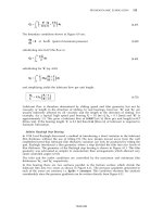
To calculate imbalance units, simply multiply the amount of imbalance by
the radius at which it is acting. In other words, 1 ounce. of imbalance at a 1-in.
radius will result in 1 oz in. of imbalance. Five ounces at a 0.5-in. radius results
in 2.5 oz in. of imbalance. (Dynamic imbalance units are measured in ounce-
inches [oz in.] or gram-millimeters [g-mm].) Although this refers to a single
plane, dynamic balancing is performed in at least two separate planes. Therefore
the tolerance is usually given in single-plane units for each plane of correction.
Important balancing techniques and concepts to be discussed in the sections to
follow include in-place balancing, single-plane versus two-plane balancing, preci-
sion balancing, techniques that make use ofa phase shift, and balancing standards.
Keith Mobley /Maintenance Fundamentals Final Proof 15.6.2004 7:32pm page 119
Rotor Balancing 119
IN-PLACE BALANCING
In most cases, weight corrections can be made with the rotor mounted in its
normal housing. The process of balancing a part without taking it out of the
machine is called in-place balancing. This technique eliminates costly and time-
consuming disassembly. It also prevents the possibility of damage to the rotor,
which can occur during removal, transportation to and from the balancing
machine, and reinstallation in the machine.
SINGLE-PLANE VERSUS TWO-PLANE BALANCING
The most common rule of thumb is that a disc-shaped rotating part usually can
be balanced in one correction plane only, whereas parts that have appreciable
width require two-plane balancing. Precision tolerances, which become more
meaningful for higher performance (even on relatively narrow face width),
suggest two-plane balancing. However, the width should be the guide, not the
diameter-to-width ratio.
For example, a 20-inch-wide rotor could have a large enough couple imbalance
component in its dynamic imbalance to require two-plane balancing. (Note: The
couple component makes two-plane balancing important.) Yet if the 20-inch
width is on a rotor of large enough diameter to qualify as a ‘‘disc-shaped rotor,’’
even some of the balance manufacturers erroneously would call for a single-plane
balance.
It is true that the narrower the rotor, the less the chance for a large couple
component and therefore the greater the possibility of getting by with a single-
plane balance. For rotors over 4–5 in. in width, it is best to check for real
dynamic imbalance (or for couple imbalance).
Unfortunately, you cannot always get by with a static- and couple-type balance,
even for very narrow flywheels used in automobiles. Although most of the
flywheels are only 1–1.5 in. wide, more than half have enough couple imbalance
to cause excessive vibration. This obviously is not caused by a large distance
between the planes (width) but rather by the fact that the flywheel’s mounting
surface can cause it to be slightly cocked or tilted. Instead of the flywheel being
90 degrees to the shaft axis, it may be perhaps 85 to 95 degrees, causing a large
couple despite its narrow width.
This situation is very common with narrow and disc-shaped industrial rotors
such as single-stage turbine wheels, narrow fans, and pump impellers. The
original manufacturer often accepts the guidelines supplied by others and
performs a single-plane balance only. By obtaining separate readings for static
Keith Mobley /Maintenance Fundamentals Final Proof 15.6.2004 7:32pm page 120
120 Maintenance Fundamentals
and couple, the manufacturer could and should easily remove the remaining
couple.
An important point to remember is that static imbalance is always removed first.
In static and couple balancing, remove the static imbalance first and then remove
the couple.
PRECISION BALANCING
Most original-equipment manufacturers balance to commercial tolerances, a
practice that has become acceptable to most buyers. However, because of
frequent customer demands, some of the equipment manufacturers now provide
precision balancing. Part of the driving force for providing this service is that
many large mills and refineries have started doing their own precision balancing
to tolerances considerably closer than those used by the original-equipment
manufacturer. For example, the International Standards Organization (ISO)
for process plant machinery calls for a G6.3 level of balancing in its balancing
guide. This was a calculated based on a rotor running free in space with a
restraint vibration of 6.3 mm/sec (0.25 in./sec) vibration velocity.
Precision balancing requires a G2.5 guide number, which is based on 2.5 mm/sec
(0.1 in./sec) vibration velocity. As can be seen from this, 6.3 mm/sec (0.25 in./sec)
balanced rotors will vibrate more than the 2.5 mm/sec (0.1 in./sec) precision bal-
anced rotors. Many vibration guidelines now consider 2.5 mm/sec (0.1 in./sec)
‘‘good,’’ creating the demand for precision balancing. Precision balancing toler-
ances can produce velocities of 0.01 in./sec (0.3 mm/sec) and lower.
It is true that the extra weight of non-rotating parts (i.e., frame and foundation)
reduces the vibration somewhat from the free-in-space amplitude. However, it is
possible to reach precision balancing levels in only two or three additional runs,
providing the smoothest running rotor. The extra effort to the balance operator
is minimal because he already has the ‘‘feel’’ of the rotor and has the proper
setup and tools in hand. In addition, there is a large financial payoff for this
minimal extra effort because of decreased bearing and seal wear.
TECHNIQUES USING PHASE SHIFT
If we assume that there is no other source of vibration other than imbalance
(i.e., we have perfect alignment, a perfectly straight shaft, etc.), it is readily seen
that pure static imbalance gives in-phase vibrations and pure coupled imbalance
gives various phase relationships. Compare the vertical reading of a bearing at
one end of the rotor with the vertical reading at the other end of the rotor to
Keith Mobley /Maintenance Fundamentals Final Proof 15.6.2004 7:32pm page 121
Rotor Balancing 121
determine how that part is shaking vertically. Then compare the horizontal
reading at one end with the horizontal reading at the other end to determine
how the part is shaking horizontally.
If there is no resonant condition to modify the resultant vibration phase, then the
phase for both vertical and horizontal readings is essentially the same, even though
the vertical and horizontal amplitudes do not necessarily correspond. In actual
practice, this may be slightly off because of other vibration sources such as
misalignment. In performing the analysis, what counts is that when the source of
the vibration is primarily from imbalance, then the vertical reading phase differ-
ences between one end of the rotor and the other will be very similar to the phase
differences when measured horizontally. For example, vibrations 60 degrees out of
phase vertically would show 60 degrees out of phase horizontally within 20%.
However, the horizontal reading on one bearing will not show the same phase
relationship as the vertical reading on the same bearing. This is caused by the
pickup axis being oriented in a different angular position as well as the phase
adjustment caused by possible resonance. For example, the horizontal vibration
frequency may be below the horizontal resonance of various major portions of
machinery, whereas the vertical vibration frequency may be above the natural
frequency of the floor supporting the machine.
First, determine how the rotor is vibrating vertically by comparing ‘‘vertical only’’
readings with each other. Then determine how the rotor is vibrating horizontally.
If the rotor is shaking horizontally and vertically and the phase differences are
relatively similar, then the source of vibration is likely to be imbalance. However,
before coming to a final conclusion, be sure that other l x rpm sources (e.g., bent
shaft, eccentric armature, misaligned coupling) are not at fault.
BALANCING STANDARDS
The ISO has published standards for acceptable limits for residual imbalance
in various classifications of rotor assemblies. Balancing standards are given in
ounce-inches or pound-inches per pound of rotor weight or the equivalent
in metric units (gram-millimeters per kilogram). The ounce-inches are for each
correction plane for which the imbalance is measured and corrected.
Caution must be exercised when using balancing standards. The recommended
levels are for residual imbalance, which is defined as imbalance of any kind that
remains after balancing.
Figure 8.1 and Table 8.1 are the norms established for most rotating equipment.
Additional information can be obtained from ISO 5406 and 5343. Similar
Keith Mobley /Maintenance Fundamentals Final Proof 15.6.2004 7:32pm page 122
122 Maintenance Fundamentals
standards are available from the American National Standards Institute (ANSI)
in their publication ANSI S2.43-1984.
So far, there has been no consideration of the angular positions of the usual two
points of imbalance relative to each other or the distance between the two correc-
tion planes. For example, if the residual imbalances in each of the two planes
were in phase, they would add to each other to create more static imbalance.
Most balancing standards are based on a residual imbalance and do not include
multi-plane imbalance. If they are approximately 180 degrees to each other, they
form a couple. If the distance between the planes is small, the resulting couple
is small; if the distance is large, the couple is large. A couple creates considerably
more vibration than when the two residual imbalances are in phase. Un-
fortunately, there is nothing in the balancing standards that takes this into
consideration.
There is another problem that could also result in excessive imbalance-related
vibration even when the ISO standards have been met. The ISO standards call
for a balancing grade of G6.3 for components such as pump impellers, normal
Balancing of Rotating Machinery
1
100,000
10,000
1000
100
10
1
0.1
0.1
0.01
0.001
0.0001
0.000010
100 1000
Speed, RPM
Acceptable Residual Unbalance Per Unit of Rotor Weight, gm mm/kg
Acceptable Residual Unbalance Per Unit of Rotor Weight, LB-IN./LB
10,000
604
61
62.3
663
616
640
6100
6250
6260
Figure 8.1 Balancing standards. Residual imbalance per unit rotor weight.
Keith Mobley /Maintenance Fundamentals Final Proof 15.6.2004 7:32pm page 123
Rotor Balancing 123
electric armatures, and parts of process plant machines. This results in an
operating speed vibration velocity of 6.3 mm/sec (0.25 in./sec) vibration velocity.
However, practice has shown that an acceptable vibration velocity is 0.1 in./sec
and the ISO standard of G2.5 is actually required. As a result of these discrep-
ancies, changes in the recommended balancing grade are expected in the future.
Table 8.1 Balance Quality Grades For Various Groups Of Rigid Rotors
Balance
Quality Grade Type Of Rotor
G4,000 Crankshaft drives of rigidly mounted slow marine diesel engines with
uneven number of cylinders
G1,600 Crankshaft drives of rigidly mounted large two-cycle engines
G630 Crankshaft drives of rigidly mounted large four-cycle engines;
crankshaft drives of elastically mounted marine diesel engines
G250 Crankshaft drives of rigidly mounted fast four-cylinder diesel engines
G100 Crankshaft drives of fast diesel engines with six or more cylinders;
complete engines (gasoline or diesel) for cars and trucks.
G40 Car wheels, wheel rims, wheel sets, drive shafts; crankshaft drives of
elastically mounted fast four-cycle engines (gasoline and diesel) with
six or more cylinders; crankshaft drives for engines of cars and trucks
G16 Parts of agricultural machinery; individual components of engines
(gasoline or diesel) for cars and trucks
G6.3 Parts or process plant machines; marine main-turbine gears;
centrifuge drums; fans; assembled aircraft gas-turbine rotors; fly
wheels; pump impellers; machine-tool and general machinery parts;
electrical armatures
G2.5 Gas and steam turbines; rigid turbo-generator rotors; rotors;
turbo-compressors; machine-tool drives; small electrical
armatures; turbine-driven pumps
G1 Tape recorder and phonograph drives; grinding-machine drives
G0.4 Spindles, disks, and armatures of precision grinders; gyroscopes
Keith Mobley /Maintenance Fundamentals Final Proof 15.6.2004 7:32pm page 124
124 Maintenance Fundamentals
9
BEARINGS
A bearing is a machine element that supports a part—such as a shaft—that
rotates, slides, or oscillates in or on it. There are two broad classifications of
bearings, plain and rolling element (also called anti-friction). Plain bearings are
based on sliding motion made possible through the use of a lubricant. Anti-
friction bearings are based on rolling motion, which is made possible by balls or
other types of rollers. In modern rotor systems operating at relatively high speeds
and loads, the proper selection and design of the bearings and bearing-support
structure are key factors affecting system life.
TYPES OF MOVEMENT
The type of bearing used in a particular application is determined by the nature
of the relative movement and other application constraints. Movement can be
grouped into the following categories: rotation about a point, rotation about a
line, translation along a line, rotation in a plane, and translation in a plane.
These movements can be either continuous or oscillating.
Although many bearings perform more than one function, they can generally be
classified based on types of movement, and there are three major classifications
of both plain and rolling element bearings: radial, thrust, and guide. Radial
bearings support loads that act radially and at right angles to the shaft center
line. These loads may be visualized as radiating into or away from a center point
like the spokes on a bicycle wheel. Thrust bearings support or resist loads that
act axially. These may be described as endwise loads that act parallel to the
center line towards the ends of the shaft. This type of bearing prevents lengthwise
or axial motion of a rotating shaft.
Keith Mobley /Maintenance Fundamentals Final Proof 15.6.2004 5:18pm page 125
125
Guide bearings support and align members having sliding or reciprocating
motion. This type of bearing guides a machine element in its lengthwise motion,
usually without rotation of the element.
Table 9.1 gives examples of bearings that are suitable for continuous movement;
Table 9.2 shows bearings that are appropriate for oscillatory movement only.
For the bearings that allow movements in addition to the one listed, the effect on
machine design is described in the column, ‘‘Effect of the Other Degrees of
Freedom.’’ Table 9.3 compares the characteristics, advantages, and disadvan-
tages of plain and rolling element bearings.
ABOUT A POINT (ROTATIONAL)
Continuous movement about a point is rotation, a motion that requires repeated
use of accurate surfaces. If the motion is oscillatory rather than continuous,
some additional arrangements must be made in which the geometric layout
prevents continuous rotation.
ABOUT A LINE (ROTATIONAL)
Continuous movement about a line is also referred to as rotation, and the same
comments apply as for movement about a point.
ALONG A LINE (TRANSLATIONAL)
Movement along a line is referred to as translation. One surface is generally long
and continuous, and the moving component is usually supported on a fluid film
or rolling contact to achieve an acceptable wear rate. If the translational move-
ment is reciprocation, the application makes repeated use of accurate surfaces,
and a variety of economical bearing mechanisms are available.
INA PLANE (ROTATIONAL//TRANSLATIONAL)
If the movement in a plane is rotational or both rotational and oscillatory, the
same comments apply as for movement about a point. If the movement in a
plane is translational or both translational and oscillatory, the same comments
apply as for movement along a line.
COMMONLY USED BEARING TYPES
As mentioned before, major bearing classifications are plain and rolling element.
These types of bearings are discussed in the sections to follow. Table 9.4 is a
Keith Mobley /Maintenance Fundamentals Final Proof 15.6.2004 5:18pm page 126
126 Maintenance Fundamentals
Table 9.1 Bearing Selection Guide (Continuous Movement)
Constraint applied to the
movement
About a point
About a line
Along a line Crane wheel restrained
between two rails
Railway or crane wheel on a
track
Pulley wheel on a cable
Hovercraft or hoverpad on a
track
Single thrust bearing Single thrust bearing must be
loaded into contact
Double thrust bearingIn a plane (rotation)
In a plane (translation) Hovercraft or hoverpad Needs to be loaded into contact
usually by gravity
These arrangements need to
be loaded into contact. This
is usually done by gravity.
Wheels on a single rail or
cable need restraint to pre-
vent rotation about the track
member
Gimbals
Journal bearing with double
thrust location
Journal bearing
Screw and nut
Ball joint
bearing
or
spherical roller Allows some angular freedom
to the line of rotation
Double conical bearing
Simple journal bearing allows
free axial movement as well
Gives some related axial
movement as well
Ball on a recessed plate
Ball must be forced into contact
with the plate
Examples of arrangements which
allow movement only within this
constraint
Examples of arrangements which
allow this movement but also have
other degrees of freedom
Effect of the other degrees o
f
freedom
Source: Bearings—A Tribology Handbook, M.J. Neale, Society of Automotive Engineers, Inc.,
Butterworth Heinemann Ltd., Oxford, Great Britain, 1993.
Keith Mobley /Maintenance Fundamentals Final Proof 15.6.2004 5:18pm page 127
Bearings 127
Table 9.2 Bearing Selection Guide (Oscillatory Movement)
Constraint applied to the
movement
Examples of arrangements which
allow movement only within this
constraint
Examples of arrangemetns which
allow this movement but alos have
other degrees of freedom
Effect of the other
degrees of freedom
About a point
About a line
Along a line
In a plane (rotation)
In a plane (translation) Plate between upper and lower
guide blocks
Rubber ring or disc
Block sliding on a plate Must be loaded into contact
Gvies some axial and lateral
flexibility as well
Crossed strip flexue pivot Torsion suspension
Knief-edge pivot
Rubber bush Gives some axial and lateral
flexibility as well
Rocker pad Gives some related translation
as well. Must be loaded into
contact
Piston and cylinderCrosshead and guide bars Piston can rotate as well unless
it is located by connecting rod
Must be loaded into contact
A single torsion suspension
gives no lateral location
Hookes joint Cable connection between
components
Cable needs to be kept in
tension
Source: Bearings—A Tribology Handbook, M.J. Neale, Society of Automotive Engineers, Inc.,
Butterworth Heinemann Ltd., Oxford, Great Britain, 1993.
Keith Mobley /Maintenance Fundamentals Final Proof 15.6.2004 5:18pm page 128
128 Maintenance Fundamentals
Table 9.3 Comparison of Plain and Rolling Element Bearings
Rolling Element Plain
Assembly on crankshaft is virtually
impossible, except with very short or
built-up crankshafts
Assembly on crankshaft is no problem as split
bearings can be used
Cost relatively high Cost relatively low
Hardness of shaft unimportant Hardness of shaft important with harder bearings
Heavier than plain bearings Lighter than rolling element bearings
Housing requirement not critical Rigidity and clamping most important housing
requirement
Less rigid than plain bearings More rigid than rolling element bearings
Life limited by material fatigue Life not generally limited by material fatigue
Lower friction results in lower
power consumption
Higher friction causes more power consumption
Lubrication easy to accomplish, the
required flow is low except at high
speed
Lubrication pressure feed critically important,
required flow is large, susceptible to damage by
contaminants and interrupted lubricant flow
Noisy operation Quiet operation
Poor tolerance of shaft deflection Moderate tolerance of shaft deflection
Poor tolerance of hard dirt particles Moderate tolerance of dirt particles, depending
on hardness of bearing
Requires more overall space: Requires less overall space:
Length: Smaller than plain Length: Larger than rolling element
Diameter: Larger than plain Diameter: Smaller than rolling element
Running Friction: Running Friction:
Very low at low speeds Higher at low speeds
May be high at high speeds Moderate at usual crank speeds
Smaller radial clearance than plain Larger radial clearance than rolling element
Source: Integrated Systems, Inc.
Keith Mobley /Maintenance Fundamentals Final Proof 15.6.2004 5:18pm page 129
Bearings 129
Table 9.4 Bearing Characteristic Summary
Bearing Type Description
Plain See Table 9.3
Lobed See Radial, Elliptical
Radial or journal
Cylindrical Gas lubricated, low-speed applications
Elliptical Oil lubricated, gear and turbine applications, stiffer and
somewhat more stable bearing
Four-axial grooved Oil lubricated, higher-speed applications than cylindrical
Partial arc Not a bearing type, but a theoretical component of grooved
and lobed bearing configurations
Tilting pad High-speed applications where hydrodynamic instability and
misalignment are common problems
Thrust Semi-fluid lubrication state, relatively high friction, lower
service pressures with multi-collar version, used at low
speeds
Rolling element See Table 9.3. Radial and axial loads, moderate- to high-
speed applications
Ball Higher speed and lighter load applications than roller
bearings
Single-row
Radial non-filling slot Also referred to as Conrad or deep-groove bearing; sustains
combined radial and thrust loads, or thrust loads alone, in
either direction, even at high speeds; not self-aligning
Radial filling slot Handles heavier loads than non-filling slot
Angular contact radial
thrust
Radial loads combined with thrust loads, or heavy thrust
loads alone; axial deflection must be limited
Ball-thrust Very high thrust loads in one direction only, no radial
loading, cannot be operated at high speeds
Keith Mobley /Maintenance Fundamentals Final Proof 15.6.2004 5:18pm page 130
130 Maintenance Fundamentals
bearings characteristics summary. Table 9.5 is a selection guide for bearings
operating with continuous rotation and special environmental conditions.
Table 9.6 is a selection guide for bearings operating with continuous rotation
and special performance requirements. Table 9.7 is a selection guide for oscillat-
ing movement and special environment or performance requirements.
PLAIN BEARINGS
All plain bearings also are referred to as fluid-film bearings. In addition, radial
plain bearings also are commonly referred to as journal bearings. Plain bearings
are available in a wide variety of types or styles and may be self-contained units
or built into a machine assembly. Table 9.8 is a selection guide for radial and
thrust plain bearings.
Plain bearings are dependent on maintaining an adequate lubricant film to
prevent the bearing and shaft surfaces from coming into contact, which is
necessary to prevent premature bearing failure.
Table 9.4 (continued )
Bearing Type Description
Double-row Heavy radial with minimal bearing deflection and light
thrust loads
Double-roll, self-aligning Moderate radial and limited thrust loads
Roller Handles heavier loads and shock better than ball bearings,
but are more limited in speed than ball bearings
Cylindrical Heavy radial loads, fairly high speeds, can allow free axial
shaft movement
Needle-type cylindrical
or barrel
Does not normally support thrust loads, used in space-
limited applications, angular mounting of rolls in double-
row version tolerates combined axial and thrust loads
Spherical High radial and moderate-to-heavy thrust loads, usually
comes in double-row mounting that is inherently self-
aligning
Tapered Heavy radial and thrust loads; can be preloaded for
maximum system rigidity
Source: Integrated Systems, Inc.
Keith Mobley /Maintenance Fundamentals Final Proof 15.6.2004 5:18pm page 131
Bearings 131
However, this is difficult to achieve, and some contact usually occurs during
operation. Material selection plays a critical role in the amount of friction and the
resulting seizure and wear that occurs with surface contact. Refer to Chapter 3
for a discussion of common bearing materials. Note that fluid-film bearings do
not have the ability to carry the full load of the rotor assembly at any speed and
must have turning gear to support the rotor’s weight at low speeds.
Table 9.5 Bearing Selection Guide For Special Environmental Conditions (Continuous Rotation)
Bearing
Type
High
Temp.
Low
Temp. Vacuum
Wet//
Humid
Dirt//
Dust
External
Vibration
Plain,
externally
pressurized
1
(With gas
lubrication)
2No
(Affected
by
lubricant
feed)
22
(1 when
gas
lubricated)
1
Plain, porous
metal (oil
impregnated)
4
(Lubricant
oxidizes)
3
(May
have high
starting
torque)
Possible
with
special
lubricant
2 Seals
essential
2
Plain,
rubbing (non-
metallic)
2
(Up to temp.
limit of
material)
212
(Shaft
must not
corrode)
2
(Seals help)
2
Plain, fluid
film
2
(Up to temp.
limit of
lubricant)
2
(May
have high
starting
torque)
Possible
with
special
lubricant
22
(With seals
and
filtration)
2
Rolling Consult
manufacturer
above 1508C
23
(With
special
lubricant)
3
(With
seals)
Sealing
essential
3
(Consult
manufacturers)
Things to
watch with all
Effect of
thermal
expansion
on fits
Effect of
thermal
expansion
on fits
Corrosion
Fretting Rating: 1–Excellent, 2–Good, 3–Fair, 4–Poor
Source: Adapted by Integrated Systems, Inc. from Bearings—A Tribology Handbook, M.J. Neale,
Society of Automotive Engineers, Inc., Butterworth Heinemann Ltd., Oxford, Great Britain, 1993.
Keith Mobley /Maintenance Fundamentals Final Proof 15.6.2004 5:18pm page 132
132 Maintenance Fundamentals
Thrust or Fixed
Thrust plain bearings consist of fixed shaft shoulders or collars that rest against
flat bearing rings. The lubrication state may be semi-fluid, and friction is rela-
tively high. In multi-collar thrust bearings, allowable service pressures are con-
siderably lower because of the difficulty in distributing the load evenly between
several collars. However, thrust ring performance can be improved by introdu-
cing tapered grooves. Figure 9.1 shows a mounting half section for a vertical
thrust bearing.
Radial or Journal
Plain radial, or journal, bearings also are referred to as sleeve or Babbit bearings.
The most common type is the full journal bearing, which has 360-degree contact
Table 9.6 Bearing Selection Guide For Particular Performance Requirements (Continuous Rotation)
Bearing
Type
Accurate
Radial
Location
Axial Load
Capacity
As Well
Low
Starting
Torque
Silent
Running
Standard
Parts
Available
Simple
Lubrication
Plain,
externally
pressurized
1 No (Need
separate
thrust
bearing)
1 1 No 4
(Need special
system)
Plain, fluid
film
3 No (Need
separate
thrust
bearing)
2 1 Some 2
(Usually
requires
circulation
system)
Plain, porous
metal (oil
impregnated)
2 Some 2 1 Yes 1
Plain,
rubbing
(non-metallic)
4 Some in
most
instances
4 3 Some 1
Rolling 2 Yes in
most
instances
1 Usually
satisfactory
Yes 2
(When grease
lubricated)
Rating: 1–Excellent/very good, 2–Good, 3–Fair, 4–Poor
Source: Adapted by Integrated Systems, Inc. from Bearings—A Tribology Handbook, M.J. Neale,
Society of Automotive Engineers, Inc., Butterworth Heinemann Ltd., Oxford, Great Britain, 1993.
Keith Mobley /Maintenance Fundamentals Final Proof 15.6.2004 5:18pm page 133
Bearings 133