(McGraw-Hill) (Instructors Manual) Electric Machinery Fundamentals 4th Edition Episode 2 Part 1 pptx
Bạn đang xem bản rút gọn của tài liệu. Xem và tải ngay bản đầy đủ của tài liệu tại đây (640.65 KB, 20 trang )
195
()
()
()
()
TH
11
30
265.6 0 V 262 0.6 V
0.33 0.42 30
M
M
j
jX
RjXX j
φ
Ω
== ∠°=∠°
++ Ω+ Ω+Ω
VV
(a) If losses are neglected, the induced torque in a motor is equal to its load torque. At full load, the
output power of this motor is 50 hp and its slip is 3.8%, so the induced torque is
()( )
1 0.038 1800 r/min 1732 r/min
m
n =− =
()( )
()
ind load
50 hp 746 W/hp
205.7 N m
2 rad 1min
1732 r/min
1 r 60 s
ττ
π
== = ⋅
The induced torque is given by the equation
()()
2
TH 2
ind
22
sync TH 2 TH 2
3/
/
VRs
RRs X X
τ
ω
=
+++
Substituting known values and solving for
2
/
Rs yields
()
()
()
()
2
2
2
2
2
3262 V /
205.7 N m
188.5 rad/s 0.321 / 0.418 0.42
Rs
Rs
⋅=
+++
()
2
2
2
205,932 /
38,774
0.321 / 0.702
Rs
Rs
=
++
()
2
22
0.321 / 0.702 5.311 /Rs Rs
++=
()
2
22 2
0.103 0.642 / / 0.702 5.311 /Rs Rs Rs
+++=
2
22
4.669 0.702 0
RR
ss
−+=
2
0.156, 4.513
R
s
=
2
0.0059 , 0.172 R =ΩΩ
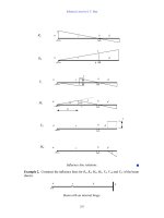
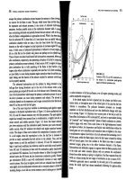
These two solutions represent two situations in which the torque-speed curve would go through this specific
torque-speed point. The two curves are plotted below. As you can see, only the 0.172
Ω
solution is
realistic, since the 0.0059
Ω
solution passes through this torque-speed point at an unstable location on the
back side of the torque-speed curve.
196
1600 1620 1640 1660 1680 1700 1720 1740 1760 1780 1800
0
50
100
150
200
250
300
350
400
450
n
m
τ
ind
Induction Motor Torque-Speed Characteristic
R2 = 0.0059 ohms
R2 = 0.172 ohms
(b) The slip at pullout torque can be found by calculating the Thevenin equivalent of the input circuit
from the rotor back to the power supply, and then using that with the rotor circuit model. The Thevenin
equivalent of the input circuit was calculate in part (a). The slip at pullout torque is
()
2
max
2
2
TH TH 2
R
s
RXX
=
++
()( )
max
22
0.172
0.192
0.321 0.418 0.420
s
Ω
==
Ω+ Ω+ Ω
The rotor speed a maximum torque is
()( )
pullout sync
(1 ) 1 0.192 1800 r/min 1454 r/minnsn=− =− =
and the pullout torque of the motor is
()
2
TH
max
2
2
sync TH TH TH 2
3V
RRXX
τ
ω
=
2+++
()
() ()( )
2
max
22
3262 V
188.5 rad/s 0.321 0.321 0.418 0.420
τ
=
2Ω+Ω+Ω+Ω
max
448 N m
τ
=⋅
(c) The starting torque of this motor is the torque at slip s = 1. It is
()()
2
TH 2
ind
22
sync TH 2 TH 2
3/
/
VRs
RRs X X
τ
ω
=
+++
()( )
()( )( )
2
ind
22
3 262 V 0.172
199 N m
188.5 rad/s 0.321 0.172 0.418 0.420
τ
Ω
==⋅
+Ω+ +
197
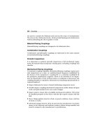
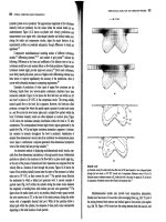
(d) To determine the starting code letter, we must find the locked-rotor kVA per horsepower, which is
equivalent to finding the starting kVA per horsepower. The easiest way to find the line current (or
armature current) at starting is to get the equivalent impedance
F
Z
of the rotor circuit in parallel with
M
jX at starting conditions, and then calculate the starting current as the phase voltage divided by the sum
of the series impedances, as shown below.
0.33
Ω
j
0.42
Ω
+
-
V
φ
I
A,
start
R
1
jX
1
R
F
jX
F
The equivalent impedance of the rotor circuit in parallel with
M
jX at starting conditions (s = 1.0) is:
,start
2
11
0.167 0.415 0.448 68.1
11 1 1
30 0.172 0.42
F
M
Zj
jX Z j j
== =+=∠°Ω
++
Ω+
The phase voltage is 460/
3
= 266 V, so line current
,startL
I is
,start
11
266 0 V
0.33 0.42 0.167 0.415
LA
FF
RjXR jX j j
φ
∠°
== =
+++ Ω+ Ω+ Ω+ Ω
V
II
,start
274 59.2 A
LA
== ∠− °II
Therefore, the locked-rotor kVA of this motor is
()()
,rated
3 3 460 V 274 A 218 kVA
TL
SVI== =
and the kVA per horsepower is
218 kVA
kVA/hp 4.36 kVA/hp
50 hp
==
This motor would have
starting code letter D, since letter D covers the range 4.00-4.50.
7-20. Answer the following questions about the motor in Problem 7-19.
(a) If this motor is started from a 460-V infinite bus, how much current will flow in the motor at starting?
(b) If transmission line with an impedance of 0.35 + j0.25
Ω
per phase is used to connect the induction
motor to the infinite bus, what will the starting current of the motor be? What will the motor’s terminal
voltage be on starting?
(c) If an ideal 1.4:1 step-down autotransformer is connected between the transmission line and the motor,
what will the current be in the transmission line during starting? What will the voltage be at the motor
end of the transmission line during starting?
S
OLUTION
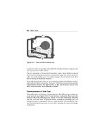
(a) The equivalent circuit of this induction motor is shown below:
198
0.33 Ω j0.42 Ω
+
-
V
φ
I
A
R
1
jX
1
R
2
−
s
s
R
1
2
jX
2
jX
M
0.172 Ωj0.42 Ω
j30 Ω
I
2
The easiest way to find the line current (or armature current) at starting is to get the equivalent impedance
F
Z
of the rotor circuit in parallel with
M
jX
at starting conditions, and then calculate the starting current
as the phase voltage divided by the sum of the series impedances, as shown below.
0.33
Ω
j
0.42
Ω
+
-
V
φ
I
A
R
1
jX
1
R
F
jX
F
The equivalent impedance of the rotor circuit in parallel with
M
jX at starting conditions (s = 1.0) is:
2
11
0.167 0.415 0.448 68.0
11 1 1
30 0.172 0.42
F
M
Zj
jX Z j j
== =+=∠°Ω
++
Ω+
The phase voltage is 460/
3
= 266 V, so line current
L
I
is
11
266 0 V
0.33 0.42 0.167 0.415
LA
FF
RjXR jX j j
φ
∠°
== =
+++ Ω+ Ω+ Ω+ Ω
V
II
273 59.2 A
LA
== ∠− °II
(b) If a transmission line with an impedance of 0.35 + j0.25
Ω
per phase is used to connect the induction
motor to the infinite bus, its impedance will be in series with the motor’s impedances, and the starting
current will be
,bus
line line 1 1
LA
FF
RjXRjXRjX
φ
==
+++++
V
II
266 0 V
0.35 0.25 0.33 0.42 0.167 0.415
LA
jj j
∠°
==
Ω+ Ω+ Ω+ Ω+ Ω+ Ω
II
193.2 52.0 A
LA
== ∠− °II
The voltage at the terminals of the motor will be
()
11AFF
RjXR jX
φ
=+++VI
()( )
194.1 52.3 A 0.33 0.42 0.167 0.415 jj
φ
= ∠− ° Ω+ Ω+ Ω+ ΩV
187.7 7.2 V
φ
=∠°V
Therefore, the terminal voltage will be
()
3 187.7 V 325 V=
. Note that the terminal voltage sagged by
about 30% during motor starting, which would be unacceptable.
199
(c) If an ideal 1.4:1 step-down autotransformer is connected between the transmission line and the motor,
the motor’s impedances will be referred across the transformer by the square of the turns ratio a = 1.4. The
referred impedances are
()
2
11
1.96 0.33 0.647 RaR== Ω= Ω
′
()
2
11
1.96 0.42 0.823 XaX== Ω= Ω′
()
2
1.96 0.167 0.327
FF
RaR== Ω= Ω
′
()
2
1.96 0.415 0.813
FF
XaX== Ω=Ω′
Therefore, the starting current referred to the primary side of the transformer will be
,bus
line line 1 1
LA
FF
RjXRjXRjX
φ
==′′
+++++
′′′ ′
V
II
266 0 V
0.35 0.25 0.647 0.823 0.327 0.813
LA
jj j
∠°
==
′′
Ω + Ω+ Ω+ Ω + Ω+ Ω
II
115.4 54.9 A
LA
== ∠− °
′′
II
The voltage at the motor end of the transmission line would be the same as the referred voltage at the
terminals of the motor
()
11AFF
RjXR jX
φ
=+++′′′ ′′ ′VI
()( )
115.4 54.9 A 0.647 0.823 0.327 0.813 jj
φ
= ∠− ° Ω+ Ω + Ω+ ΩV
219.7 4.3 V
φ
=∠°V
Therefore, the line voltage at the motor end of the transmission line will be
(
)
3 219.7 V 380.5 V=
. Note
that this voltage sagged by 17.3% during motor starting, which is less than the 30% sag with case of
across-the-line starting.
7-21. In this chapter, we learned that a step-down autotransformer could be used to reduce the starting current
drawn by an induction motor. While this technique works, an autotransformer is relatively expensive. A
much less expensive way to reduce the starting current is to use a device called Y-∆ starter. If an induction
motor is normally
∆
-connected, it is possible to reduce its phase voltage
V
φ
(and hence its starting current)
by simply re-connecting the stator windings in Y during starting, and then restoring the connections to ∆
when the motor comes up to speed. Answer the following questions about this type of starter.
(a) How would the phase voltage at starting compare with the phase voltage under normal running
conditions?
(b) How would the starting current of the Y-connected motor compare to the starting current if the motor
remained in a ∆-connection during starting?
S
OLUTION
(a) The phase voltage at starting would be 1 /
3
= 57.7% of the phase voltage under normal running
conditions.
(b) Since the phase voltage decreases to 1 /
3
= 57.7% of the normal voltage, the starting phase current
will also decrease to 57.7% of the normal starting current. However, since the line current for the original
delta connection was
3
times the phase current, while the line current for the Y starter connection is
equal to its phase current, the line current is reduced by a factor of 3 in a Y-
∆
starter.
For the
∆
-connection:
,,
3
L
II
φ
∆∆
=
200
For the Y-connection:
,Y ,YL
II
φ
=
But
,,Y
3 II
φφ
∆
=
, so
,,Y
3
LL
II
∆
=
7-22. A 460-V 100-hp four-pole
∆
-connected 60-Hz three-phase induction motor has a full-load slip of 5 percent,
an efficiency of 92 percent, and a power factor of 0.87 lagging. At start-up, the motor develops 1.9 times
the full-load torque but draws 7.5 times the rated current at the rated voltage. This motor is to be started
with an autotransformer reduced voltage starter.
(a) What should the output voltage of the starter circuit be to reduce the starting torque until it equals the
rated torque of the motor?
(b) What will the motor starting current and the current drawn from the supply be at this voltage?
S
OLUTION
(a) The starting torque of an induction motor is proportional to the square of
TH
V
,
22
start2 TH2 2
start1 TH1 1
T
T
VV
VV
τ
τ
==
If a torque of 1.9
rated
τ
is produced by a voltage of 460 V, then a torque of 1.00
rated
τ
would be produced
by a voltage of
2
rated 2
rated
1.00
1.90 460 V
T
V
τ
τ
=
()
2
2
460 V
334 V
1.90
T
V ==
(b) The motor starting current is directly proportional to the starting voltage, so
()()
()
2 1 1 rated rated
334 V
0.726 0.726 7.5 5.445
460 V
LLL
III II
=== =
The input power to this motor is
()( )
OUT
IN
100 hp 746 W/hp
81.1 kW
0.92
P
P
η
== =
The rated current is equal to
()
()()
IN
rated
81.1 kW
117 A
3 PF 3 460 V 0.87
T
P
I
V
== =
Therefore, the motor starting current is
()( )
2 rated
5.445 5.445 117 A 637 A
L
II== =
The turns ratio of the autotransformer that produces this starting voltage is
460 V
1.377
334 V
SE C
C
NN
N
+
==
so the current drawn from the supply will be
201
start
line
637 A
463 A
1.377 1.377
I
I == =
7-23.
A wound-rotor induction motor is operating at rated voltage and frequency with its slip rings shorted and
with a load of about 25 percent of the rated value for the machine. If the rotor resistance of this machine is
doubled by inserting external resistors into the rotor circuit, explain what happens to the following:
(a) Slip s
(b) Motor speed
n
m
(c) The induced voltage in the rotor
(d) The rotor current
(e)
ind
τ
(f)
out
P
(g)
RCL
P
(h) Overall efficiency
η
S
OLUTION
(a) The slip s will increase.
(b) The motor speed
m
n
will decrease.
(c) The induced voltage in the rotor will increase.
(d) The rotor current will increase.
(e) The induced torque will adjust to supply the load’s torque requirements at the new speed. This will
depend on the shape of the load’s torque-speed characteristic. For most loads, the induced torque will
decrease.
(f) The output power will generally decrease:
OUT ind m
P
τω
=↓↓
(g) The rotor copper losses (including the external resistor) will increase.
202
(h) The overall efficiency
η
will decrease.
7-24. Answer the following questions about a 460-V
∆
-connected two-pole 75-hp 60-Hz starting code letter E
induction motor:
(a) What is the maximum current starting current that this machine’s controller must be designed to
handle?
(b) If the controller is designed to switch the stator windings from a ∆ connection to a Y connection during
starting, what is the maximum starting current that the controller must be designed to handle?
(c) If a 1.25:1 step-down autotransformer starter is used during starting, what is the maximum starting
current that will be drawn from the line?
S
OLUTION
(a) Starting code letter E corresponds to a 4.50 – 5.00 kVA/hp, so the maximum starting kVA of this
motor is
()()
start
75 hp 5.00 375 kVAS ==
Therefore,
()
start
375 kVA
471 A
3 3 460 V
T
S
I
V
== =
(b) The line voltage will still be 460 V when the motor is switched to the Y-connection, but now the
phase voltage will be 460 /
3
= 266 V.
Before (in
∆
):
()( )()( )
,
,
TH2TH2TH2TH2
460 V
V
I
RRjX X RRjX X
φ
φ
∆
∆
==
++ + ++ +
But the line current in a
∆
connection is
3 times the phase current, so
()( )()( )
,
,,
TH 2 TH 2 TH 2 TH 2
3
797 V
3
L
V
II
RRjX X RRjX X
φ
φ
∆
∆∆
== =
++ + ++ +
After (in Y):
()( )()( )
,Y
,Y ,Y
TH 2 TH 2 TH 2 TH 2
265.6 V
L
V
II
RRjX X RRjX X
φ
φ
== =
++ + ++ +
Therefore the line current will decrease by a factor of 3 when using this starter. The starting current with a
∆
-Y starter is
start
471 A
157 A
3
I ==
(c) A 1.25:1 step-down autotransformer reduces the phase voltage on the motor by a factor 0.8. This
reduces the phase current and line current in the motor (and on the secondary side of the transformer) by a
factor of 0.8. However, the current on the primary of the autotransformer will be reduced by another factor
of 0.8, so the total starting current drawn from the line will be 64% of its original value. Therefore, the
maximum starting current drawn from the line will be
()( )
start
0.64 471 A 301 AI ==
203
7-25. When it is necessary to stop an induction motor very rapidly, many induction motor controllers reverse the
direction of rotation of the magnetic fields by switching any two stator leads. When the direction of
rotation of the magnetic fields is reversed, the motor develops an induced torque opposite to the current
direction of rotation, so it quickly stops and tries to start turning in the opposite direction. If power is
removed from the stator circuit at the moment when the rotor speed goes through zero, then the motor has
been stopped very rapidly. This technique for rapidly stopping an induction motor is called plugging. The
motor of Problem 7-19 is running at rated conditions and is to be stopped by plugging.
(a) What is the slip s before plugging?
(b) What is the frequency of the rotor before plugging?
(c) What is the induced torque
ind
τ
before plugging?
(d) What is the slip s immediately after switching the stator leads?
(e) What is the frequency of the rotor immediately after switching the stator leads?
(f) What is the induced torque
ind
τ
immediately after switching the stator leads?
S
OLUTION
(a) The slip before plugging is 0.038 (see Problem 7-19).
(b) The frequency of the rotor before plugging is
()( )
0.038 60 Hz 2.28 Hz
re
fsf== =
(c) The induced torque before plugging is 205.7 N⋅m in the direction of motion (see Problem 7-19).
(d) After switching stator leads, the synchronous speed becomes –1800 r/min, while the mechanical speed
initially remains 1732 r/min. Therefore, the slip becomes
sync
sync
1800 1732
1.962
1800
m
nn
s
n
−
−−
== =
−
(e) The frequency of the rotor after plugging is
()( )
1.962 60 Hz 117.72 Hz
re
fsf== =
(f) The induced torque immediately after switching the stator leads is
()()
2
TH 2
ind
22
sync TH 2 TH 2
3/
/
VRs
RRs X X
τ
ω
=
+++
()( )
()( )( )
2
ind
22
3 262 V 0.172 /1.962
188.5 rad/s 0.321 0.172 /1.962 0.418 0.420
τ
Ω
=
+Ω + +
()( )
()( )( )
2
ind
22
3262 V 0.0877
188.5 rad/s 0.321 0.0877 0.418 0.420
τ
=
+++
ind
110 N m, opposite the direction of motion
τ
=⋅
204
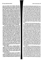
Chapter 8:
DC Machinery Fundamentals
8-1. The following information is given about the simple rotating loop shown in Figure 8-6:
0.8 T B = 24 V
B
V =
0.5 ml
=
0.4 R
=Ω
0.125 mr = 250 rad/s
ω
=
(a) Is this machine operating as a motor or a generator? Explain.
(b) What is the current i flowing into or out of the machine? What is the power flowing into or out of the
machine?
(c) If the speed of the rotor were changed to 275 rad/s, what would happen to the current flow into or out
of the machine?
(d) If the speed of the rotor were changed to 225 rad/s, what would happen to the current flow into or out
of the machine?
205
(a) If the speed of rotation
ω
of the shaft is 500 rad/s, then the voltage induced in the rotating loop will be
ind
2erlB
ω
=
(
)
(
)
(
)
(
)
ind
2 0.125 m 0.5 m 0.8 T 250 rad/s 25 Ve ==
Since the external battery voltage is only 24 V, this machine is operating as a generator, charging the
battery.
(b) The current flowing out of the machine is approximately
ind
25 V 24 V
2.5 A
0.4
B
eV
i
R
−−
== =
Ω
(Note that this value is the current flowing while the loop is under the pole faces. When the loop goes
beyond the pole faces,
ind
e
will momentarily fall to 0 V, and the current flow will momentarily reverse.
Therefore, the average current flow over a complete cycle will be somewhat less than 2.5 A.)
(c) If the speed of the rotor were increased to 275 rad/s, the induced voltage of the loop would increase to
ind
2erlB
ω
=
(
)
(
)
(
)
(
)
ind
2 0.125 m 0.5 m 0.8 T 275 rad/s 27.5 Ve ==
and the current flow out of the machine will increase to
ind
27.5 V 24 V
8.75 A
0.4
B
eV
i
R
−−
== =
Ω
(d) If the speed of the rotor were decreased to 450 rad/s, the induced voltage of the loop would fall to
ind
2erlB
ω
=
()()()( )
ind
2 0.125 m 0.5 m 0.8 T 225 rad/s 22.5 Ve ==
Here,
ind
e is less than
B
V , so current flows into the loop and the machine is acting as a motor. The current
flow into the machine would be
ind
24 V - 22.5 V
3.75 A
0.4
B
Ve
i
R
−
== =
Ω
8-2. Refer to the simple two-pole eight-coil machine shown in Figure P8-1. The following information is given
about this machine:
B = 10. T in air gap
l = 03. m (length of coil sides)
coils) of (radiusm 08.0=r
CCWr/min 1700=n
The resistance of each rotor coil is 0.04
Ω
.
(a) Is the armature winding shown a progressive or retrogressive winding?
(b) How many current paths are there through the armature of this machine?
(c) What are the magnitude and the polarity of the voltage at the brushes in this machine?
(d) What is the armature resistance
R
A
of this machine?
206
(e) If a 10
Ω
resistor is connected to the terminals of this machine, how much current flows in the
machine? Consider the internal resistance of the machine in determining the current flow.
(f) What are the magnitude and the direction of the resulting induced torque?
(g) Assuming that the speed of rotation and magnetic flux density are constant, plot the terminal voltage of
this machine as a function of the current drawn from it.
S
OLUTION
(a) This winding is progressive, since the ends of each coil are connected to the commutator segments
ahead of the segments that the beginnings of the coils are connected to.
(b) There are two current paths in parallel through the armature of this machine (this is a simplex lap
winding).
(c) The voltage is positive at brush x with respect to brush y, since the voltage in the conductors is
positive out of the page under the North pole face and positive into the page under the South pole face.
(d) There are 8 coils on this machine in two parallel paths, with each coil having a resistance of 0.04
Ω
.
Therefore, the total resistance
A
R
is
()()
0.04 0.04 0.04 0.04 0.04 0.04 0.04 0.04
0.04 0.04 0.04 0.04 0.04 0.04 0.04 0.04
A
R
Ω+ Ω+ Ω+ Ω Ω+ Ω+ Ω+ Ω
=
Ω+ Ω+ Ω+ Ω+ Ω+ Ω+ Ω+ Ω
207
0.08
A
R =Ω
(e) The voltage produced by this machine can be found from Equations 8-32 and 8-33:
A
Z
vBl Zr Bl
E
aa
ω
==
where Z is the number of conductors under the pole faces, since the ones between the poles have no voltage
in them. There are 16 conductors in this machine, and about 12 of them are under the pole faces at any
given time.
()
2 rad 1 min
1700 r/min 178 rad/s
1 r 60 s
π
ω
==
()()( )()()
12 cond 0.08 m 178 rad/s 1.0 T 0.3 m
25.6 V
2 current paths
A
Zr Bl
E
a
ω
== =
Therefore, the current flowing in the machine will be
load
25.6 V
2.54 A
0.08 10
A
A
A
E
I
RR
== =
+Ω+Ω
(f) The induced torque is given by Equation 8-46:
( )()()()()
ind
12 cond 0.08 m 0.3 m 1.0 T 2.54 A
2 current paths
A
ZrlBI
a
τ
==
CW m,N 366.0
ind
⋅=
τ
(opposite to the direction of rotation)
8-3. Prove that the equation for the induced voltage of a single simple rotating loop
ind
2
e
φ
ω
π
= (8-6)
is just a special case of the general equation for induced voltage in a dc machine
A
EK
φ
ω
= (8-38)
S
OLUTION
From Equation 8-38,
A
EK
φ
ω
=
where
2
Z
P
K
a
π
=
For the simple rotation loop,
Z = 2 (There are 2 conductors)
P = 2 (There are 2 poles)
a = 1 (There is one current path through the machine)
Therefore,
()()
()
2 2
2
22 1
ZP
K
a
ππ π
==
and Equation 8-38 reduces to Equation 8-6.
8-4. A dc machine has 8 poles and a rated current of 100 A. How much current will flow in each path at rated
conditions if the armature is (a) simplex lap-wound, (b) duplex lap-wound, (c) simplex wave-wound?
S
OLUTION
208
(a) Simplex lap-wound
:
()()
18 8 pathsamP== =
Therefore, the current per path is
100 A
12.5 A
8
A
I
I
a
== =
(b) Duplex lap-wound
:
()()
2 8 16 pathsamP== =
Therefore, the current per path is
100 A
6.25 A
16
A
I
I
a
== =
(c) Simplex wave-wound
:
()()
2212 pathsam== =
Therefore, the current per path is
100 A
50 A
2
A
I
I
a
== =
8-5. How many parallel current paths will there be in the armature of a 12-pole machine if the armature is (a)
simplex lap-wound, (b) duplex wave-wound, (c) triplex lap-wound, (d) quadruplex wave-wound?
S
OLUTION
(a) Simplex lap-wound
:
(1)(12) 12 pathsamP
== =
(b) Duplex wave-wound
:
2 (2)(2) 4 pathsam== =
(c) Triplex lap-wound
:
(3)(12) 36 pathsamP== =
(d) Quadruplex wave-wound
:
2 (2)(4) 8 pathsam== =
8-6. The power converted from one form to another within a dc motor was given by
conv indAA m
PEI
τω
==
Use the equations for
A
E and
ind
τ
[Equations (8-38) and (8-49)] to prove that
AA
EI =
m
ωτ
ind
; that is,
prove that the electric power disappearing at the point of power conversion is exactly equal to the
mechanical power appearing at that point.
S
OLUTION
conv AA
PEI=
Substituting Equation (8-38) for
A
E
209
()
conv
A
PKI
φω
=
()
conv
A
PKI
φ
ω
=
But from Equation (8-49),
ind
A
KI
τφ
= , so
conv ind
P
τω
=
8-7. An eight-pole, 25-kW, 120-V DC generator has a duplex lap-wound armature, which has 64 coils with 16
turns per coil. Its rated speed is 2400 r/min.
(a) How much flux per pole is required to produce the rated voltage in this generator at no-load conditions?
(b) What is the current per path in the armature of this generator at the rated load?
(c) What is the induced torque in this machine at the rated load?
(d) How many brushes must this motor have? How wide must each one be?
(e) If the resistance of this winding is 0.011
Ω
per turn, what is the armature resistance
A
R of this
machine?
S
OLUTION
(a)
2
A
ZP
EK
a
φ
ωφω
π
==
In this machine, the number of current paths is
()()
28 16amP== =
The number of conductor is
()( )( )
64 coils 16 turns/coil 2 conductors/turn 2048Z ==
The equation for induced voltage is
2
A
ZP
E
a
φ
ω
π
=
so the required flux is
()()
()
()
2048 cond 8 poles
2 rad 1 min
120 V 2400 r/min
2 16 paths 1 r 60 s
π
φ
π
=
120 V 40,960
φ
=
0.00293 Wb
φ
=
(b) At rated load, the current flow in the generator would be
25 kW
208 A
120 V
A
I ==
There are a = m
P = (2)(8) = 16 parallel current paths through the machine, so the current per path is
208 A
13 A
16
A
I
I
a
== =
(c) The induced torque in this machine at rated load is
ind
2
A
ZP
I
a
τφ
π
=
210
()()
()
()()
ind
2048 cond 8 poles
0.00293 Wb 208 A
216 paths
τ
π
=
ind
99.3 N m
τ
=⋅
(d) This motor must have 8 brushes, since it is lap-wound and has 8 poles. Since it is duplex-wound,
each brush must be wide enough to stretch across 2 complete commutator segments.
(e) There are a total of 1024 turns on the armature of this machine, so the number of turns per path is
1024 turns
64 turns/path
16 paths
P
N ==
The total resistance per path is
()( )
64 0.011 0.704
P
R =Ω=Ω. Since there are 16 parallel paths through
the machine, the armature resistance of the generator is
0.704
0.044
16 paths
A
R
Ω
==Ω
8-8. Figure P8-2 shows a small two-pole dc motor with eight rotor coils and four turns per coil. The flux per
pole in this machine is 0.0125 Wb.
(a) If this motor is connected to a 12-V dc car battery, what will the no-load speed of the motor be?
(b) If the positive terminal of the battery is connected to the rightmost brush on the motor, which way will
it rotate?
(c) If this motor is loaded down so that it consumes 50 W from the battery, what will the induced torque of
the motor be? (Ignore any internal resistance in the motor.)
S
OLUTION
(a) At no load,
TA
VEK
φ
ω
== . If K is known, then the speed of the motor can be found. The constant
K is given by
2
Z
P
K
a
π
=
On the average, about 6 of the 8 coils are under the pole faces at any given time, so the average number of
active conductors is
Z = (6 coils)(4 turns/coil)(2 conductors/turn) = 48 conductors
211
There are two poles and two current paths, so
()()
()
48 cond 2 poles
7.64
2 2 2 paths
ZP
K
a
ππ
== =
The speed is given by
()( )
12 V
125.6 rad/s
7.64 0.0125 Wb
A
E
K
ω
φ
== =
()
1 r 60 s
125.6 rad/s 1200 r/min
2 rad 1 min
m
n
π
==
(b) If the positive terminal of the battery is connected to the rightmost brush, current will flow into the
page under the South pole face, producing a CW torque
⇒
CW rotation.
(c) If the motor consumes 50 W from the battery, the current flow is
50 W
4.17 A
12 V
B
P
I
V
== =
Therefore, the induced torque will be
()( )( )
ind
7.64 0.0125 Wb 4.17 A 0.40 N m, CW
A
KI
τφ
== = ⋅
8-9. Refer to the machine winding shown in Figure P8-3.
(a) How many parallel current paths are there through this armature winding?
(b) Where should the brushes be located on this machine for proper commutation? How wide should they
be?
(c) What is the plex of this machine?
(d) If the voltage on any single conductor under the pole faces in this machine is e, what is the voltage at
the terminals of this machine?
212
S
OLUTION
(a) This is a duplex, two-pole, lap winding, so there are 4 parallel current paths through the rotor.
(b) The brushes should be shorting out those windings lying between the two poles. At the time shown,
those windings are 1, 2, 9, and 10. Therefore, the brushes should be connected to short out commutator
segments b-c-d and j-k-l at the instant shown in the figure. Each brush should be two commutator
segments wide, since this is a duplex winding.
(c) Duplex (see above)
(d) There are 16 coils on the armature of this machine. Of that number, an average of 14 of them would
be under the pole faces at any one time. Therefore, there are 28 conductors divided among 4 parallel paths,
which produces 7 conductors per path. Therefore,
TA
VeE == 7 for no-load conditions.
213
8-10. Describe in detail the winding of the machine shown in Figure P8-4. If a positive voltage is applied to the
brush under the North pole face, which way will this motor rotate?
S
OLUTION
This is a 2-pole, retrogressive, lap winding. If a positive voltage is applied to the brush under
the North pole face, the rotor will rotate in a counterclockwise direction.
214
Chapter 9:
DC Motors and Generators
Problems 9-1 to 9-12 refer to the following dc motor:
P
rated
= 15 hp I
L,rated
= 55 A
V
T
= 240 V N
F
= 2700 turns per pole
n
rated
= 1200 r/min N
SE
= 27 turns per pole
R
A
= 0.40
Ω
R
F
= 100
Ω
R
S
= 0.04
Ω
R
adj
= 100 to 400
Ω
Rotational losses = 1800 W at full load. Magnetization curve as shown in Figure P9-1.
Note: An electronic version of this magnetization curve can be found in file
p91_mag.dat, which can be used with MATLAB programs. Column 1
contains field current in amps, and column 2 contains the internal generated
voltage E
A
in volts.
In Problems 9-1 through 9-7, assume that the motor described above can be connected in shunt. The equivalent
circuit of the shunt motor is shown in Figure P9-2.