(McGraw-Hill) (Instructors Manual) Electric Machinery Fundamentals 4th Edition Episode 2 Part 5 ppsx
Bạn đang xem bản rút gọn của tài liệu. Xem và tải ngay bản đầy đủ của tài liệu tại đây (645.04 KB, 20 trang )
275
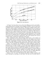
The resulting torque-speed characteristic is shown below:
10-5. A 220-V, 1.5-hp 50-Hz, two-pole, capacitor-start induction motor has the following main-winding
impedances:
1
R = 1.40
Ω
1
X = 2.01
Ω
M
X = 105
Ω
2
R = 1.50
Ω
2
X = 2.01
Ω
At a slip of 0.05, the motor’s rotational losses are 291 W. The rotational losses may be assumed constant
over the normal operating range of the motor. Find the following quantities for this motor at 5 percent slip:
(a) Stator current
(b) Stator power factor
(c) Input power
(d)
AG
P
(e) P
conv
(f)
out
P
(g)
ind
τ
(h)
load
τ
(i) Efficiency
S
OLUTION
The equivalent circuit of the motor is shown below
276
1.4 Ω j1.9 Ω
+
-
V = 220∠0° V
I
1
R
1
jX
1
s
R
2
5.0
j0.5X
2
j0.5X
M
j1.90 Ω
j30 Ω
s
R
−2
5.0
2
jX
2
j1.90 Ω
j0.5X
M
j100 Ω
{
{
{
{
Forward
Reverse
0.5Z
B
0.5Z
F
()()
22
22
/
/
M
F
M
Rs jX jX
Z
R s jX jX
+
=
++
()()
30 1.90 100
26.59 9.69
30 1.90 100
F
jj
Zj
jj
+
==+Ω
++
()
()
()
22
22
/2
/2
M
B
M
R s jX jX
Z
R s jX jX
=
−+ +
()()
0.769 1.90 100
0.741 1.870
0.769 1.90 100
B
jj
Zj
jj
+
==+Ω
++
(a) The input stator current is
1
11
I
0.5 0.5
FB
RjX Z Z
=
++ +
V
()( )( )
1
220 0 V
I 13.0 27.0 A
1.40 1.90 0.5 26.59 9.69 0.5 0.741 1.870jjj
∠°
==∠−°
++ ++ +
(b) The stator power factor is
PF cos 27 0.891 lagging
=°=
(c) The input power is
()()
IN
cos 220 V 13.0 A cos 27 2548 WPVI
θ
== °=
(d) The air-gap power is
()
()( )
2
2
AG, 1
0.5 13.0 A 13.29 2246 W
FF
PIR== Ω=
()
()( )
2
2
AG, 1
0.5 13.0 A 0.370 62.5 W
BB
PIR== Ω=
AG AG, AG,
2246 W 62.5 W 2184 W
FB
PP P=−= − =
277
(e) The power converted from electrical to mechanical form is
() ( )( )
conv, AG,
1 1 0.05 2246 W 2134 W
FF
PsP=− =− =
() ( )( )
conv, AG,
1 1 0.05 62.5 W 59 W
BB
PsP=− =− =
conv conv, conv,
2134 W 59 W 2075 W
FB
PP P=−= −=
(f) The output power is
OUT conv rot
2134 W 291 W 1843 WPPP=−= − =
(g) The induced torque is
()
AG
ind
sync
2184 W
6.95 N m
2 rad 1 min
3000 r/min
1 r 60 s
P
τ
π
ω
== = ⋅
(h) The load torque is
()( )
OUT
load
1843 W
6.18 N m
2 rad 1 min
0.95 3000 r/min
1 r 60 s
m
P
τ
π
ω
== = ⋅
(i) The overall efficiency is
OUT
IN
1843 W
100% 100% 72.3%
2548 W
P
P
η
=× = × =
10-6. Find the induced torque in the motor in Problem 10-5 if it is operating at 5 percent slip and its terminal
voltage is (a) 190 V, (b) 208 V, (c) 230 V.
()()
22
22
/
/
M
F
M
Rs jX jX
Z
R s jX jX
+
=
++
()()
30 1.90 100
26.59 9.69
30 1.90 100
F
jj
Zj
jj
+
==+Ω
++
()
()
()
22
22
/2
/2
M
B
M
R s jX jX
Z
R s jX jX
=
−+ +
()()
0.769 1.90 100
0.741 1.870
0.769 1.90 100
B
jj
Zj
jj
+
==+Ω
++
(a) If
T
V
= 190∠0° V,
1
11
I
0.5 0.5
FB
RjX Z Z
=
++ +
V
()( )( )
1
190 0 V
I 11.2 27.0 A
1.40 1.90 0.5 26.59 9.69 0.5 0.741 1.870jjj
∠°
==∠−°
++ ++ +
()
()( )
2
2
AG, 1
0.5 11.2 A 13.29 1667 W
FF
PIR== Ω=
()
()( )
2
2
AG, 1
0.5 11.2 A 0.370 46.4 W
BB
PIR== Ω=
AG AG, AG,
1667 W 46.4 W 1621 W
FB
PP P=−= − =
278
()
AG
ind
sync
1621 W
5.16 N m
2 rad 1 min
3000 r/min
1 r 60 s
P
τ
π
ω
== = ⋅
(b) If
T
V
= 208∠0° V,
1
11
I
0.5 0.5
FB
RjX Z Z
=
++ +
V
()( )( )
1
208 0 V
I12.327.0 A
1.40 1.90 0.5 26.59 9.69 0.5 0.741 1.870jjj
∠°
==∠−°
++ ++ +
()
()( )
2
2
AG, 1
0.5 12.3 A 13.29 2010 W
FF
PIR== Ω=
()
()( )
2
2
AG, 1
0.5 12.3 A 0.370 56 W
BB
PIR== Ω=
AG AG, AG,
2010 W 56 W 1954 W
FB
PP P=−= − =
()
AG
ind
sync
1954 W
6.22 N m
2 rad 1 min
3000 r/min
1 r 60 s
P
τ
π
ω
== = ⋅
(c) If
T
V = 230
∠
0
°
V,
1
11
I
0.5 0.5
FB
RjX Z Z
=
++ +
V
()( )( )
1
230 0 V
I 13.6 27.0 A
1.40 1.90 0.5 26.59 9.69 0.5 0.741 1.870jjj
∠°
==∠−°
++ ++ +
()
()( )
2
2
AG, 1
0.5 13.6 A 13.29 2458 W
FF
PIR== Ω=
()
()( )
2
2
AG, 1
0.5 13.6 A 0.370 68 W
BB
PIR== Ω=
AG AG, AG,
2458 W 68 W 2390 W
FB
PP P=−= − =
()
AG
ind
sync
2390 W
7.61 N m
2 rad 1 min
3000 r/min
1 r 60 s
P
τ
π
ω
== = ⋅
Note that the induced torque is proportional to the square of the terminal voltage.
10-7. What type of motor would you select to perform each of the following jobs? Why?
(a) Vacuum cleaner (b) Refrigerator
(c) Air conditioner compressor (d) Air conditioner fan
(e) Variable-speed sewing machine (f) Clock
(g) Electric drill
S
OLUTION
(a) Universal motor—for its high torque
(b) Capacitor start or Capacitor start and run—For its high starting torque and relatively constant
speed at a wide variety of loads
(c) Same as (b) above
279
(d) Split-phase—Fans are low-starting-torque applications, and a split-phase motor is appropriate
(e) Universal Motor—Direction and speed are easy to control with solid-state drives
(f) Hysteresis motor—for its easy starting and operation at
sync
n
. A reluctance motor would also do
nicely.
(g) Universal Motor—for easy speed control with solid-state drives, plus high torque under loaded
conditions.
10-8. For a particular application, a three-phase stepper motor must be capable of stepping in 10° increments.
How many poles must it have?
S
OLUTION
From Equation (10-18), the relationship between mechanical angle and electrical angle in a
three-phase stepper motor is
2
me
P
θθ
=
so
60
2 2 12 poles
10
e
m
P
θ
θ
°
== =
°
10-9. How many pulses per second must be supplied to the control unit of the motor in Problem 10-7 to achieve a
rotational speed of 600 r/min?
S
OLUTION
From Equation (10-20),
pulses
1
3
m
nn
P
=
so
()( )
pulses
3 3 12 poles 600 r/min 21,600 pulses/min 360 pulses/s
m
nPn== = =
10-10. Construct a table showing step size versus number of poles for three-phase and four-phase stepper motors.
S
OLUTION
For 3-phase stepper motors,
°= 60
e
θ
, and for 4-phase stepper motors,
°= 45
e
θ
. Therefore,
Number of poles Mechanical Step Size
3-phase ( 60
e
θ
=°) 4-phase ( 45
e
θ
=°)
2
60
° 45°
4
30
°
22.5
°
6
20
°
15
°
8
15
° 11.25°
10
12
°
9
°
12
10
° 7.5°
280
Appendix A:
Review of Three-Phase Circuits
A-1. Three impedances of 4 + j3 Ω are ∆-connected and tied to a three-phase 208-V power line. Find
I
φ
,
I
L
,
P, Q, S, and the power factor of this load.
S
OLUTION
Z
φ
Z
φ
Z
φ
+
-
240 V
I
L
I
φ
Ω+= 43 jZ
φ
Here, 208 V
L
VV
φ
== , and 4 3 5 36.87 Zj
φ
=+ Ω=∠ °Ω, so
208 V
41.6 A
5
V
I
Z
φ
φ
φ
== =
Ω
()
3 3 41.6 A 72.05 A
L
II
φ
== =
()
2
2
208 V
3 cos 3 cos 36.87 20.77 kW
5
V
P
Z
φ
θ
== °=
Ω
()
2
2
208 V
3 sin 3 sin 36.87 15.58 kvar
5
V
Q
Z
φ
θ
== °=
Ω
22
25.96 kVASPQ=+=
PF cos 0.8 lagging
θ
==
A-2. Figure PA-1 shows a three-phase power system with two loads. The ∆-connected generator is producing a
line voltage of 480 V, and the line impedance is 0.09 + j0.16
Ω
. Load 1 is Y-connected, with a phase
impedance of 2.5
∠36.87° Ω and load 2 is ∆-connected, with a phase impedance of 5∠-20° Ω.
281
(a) What is the line voltage of the two loads?
(b) What is the voltage drop on the transmission lines?
(c) Find the real and reactive powers supplied to each load.
(d) Find the real and reactive power losses in the transmission line.
(e) Find the real power, reactive power, and power factor supplied by the generator.
S
OLUTION
To solve this problem, first convert the two deltas to equivalent wyes, and get the per-phase
equivalent circuit.
+
-
277
∠
0° V
Line
0.090
Ω
j
0.16
Ω
1
φ
Z
2
φ
Z
Ω°∠= 87.365.2
1
φ
Z
Ω°−∠= 2067.1
2
φ
Z
load,
φ
V
+
-
(a) The phase voltage of the equivalent Y-loads can be found by nodal analysis.
,load ,load ,load
277 0 V
0
0.09 0.16 2.5 36.87 1.67 20 j
φφφ
−∠°
++=
+Ω ∠°Ω∠−°Ω
VVV
()
(
)
()()
,load ,load ,load
5.443 60.6 277 0 V 0.4 36.87 0.6 20 0
φφφ
∠−° −∠°+∠− ° +∠° =VVV
()
,load
5.955 53.34 1508 60.6
φ
∠− ° = ∠− °V
,load
253.2 7.3 V
φ
=∠−°V
282
Therefore, the line voltage at the loads is
3 439 V
L
VV
φ
= .
(b) The voltage drop in the transmission lines is
line ,gen ,load
277 0 V 253.2 -7.3 41.3 52 V
φφ
∆=−=∠°−∠°=∠°VV V
(c) The real and reactive power of each load is
()
2
2
1
253.2 V
3 cos 3 cos 36.87 61.6 kW
2.5
V
P
Z
φ
θ
== °=
Ω
()
2
2
1
253.2 V
3 sin 3 sin 36.87 46.2 kvar
2.5
V
Q
Z
φ
θ
== °=
Ω
()
()
2
2
2
253.2 V
3 cos 3 cos -20 108.4 kW
1.67
V
P
Z
φ
θ
== °=
Ω
()
()
2
2
2
253.2 V
3 sin 3 sin -20 39.5 kvar
1.67
V
Q
Z
φ
θ
== °=−
Ω
(d) The line current is
line
line
line
41.3 52 V
225 8.6 A
0.09 0.16 Zj
∆∠°
== =∠−°
+Ω
V
I
Therefore, the loses in the transmission line are
()( )
2
2
line line line
3 3 225 A 0.09 13.7 kWPIR== Ω=
()( )
2
2
line line line
3 3 225 A 0.16 24.3 kvarQIX== Ω=
(e) The real and reactive power supplied by the generator is
gen line 1 2
13.7 kW 61.6 kW 108.4 kW 183.7 kWPPPP=++= + + =
gen line 1 2
24.3 kvar 46.2 kvar 39.5 kvar 31 kvarQQQQ=++= + − =
The power factor of the generator is
gen
-1 1
gen
31 kvar
PF cos tan cos tan 0.986 lagging
183.7 kW
Q
P
−
== =
A-3. Figure PA-2 shows a one-line diagram of a simple power system containing a single 480 V generator and
three loads. Assume that the transmission lines in this power system are lossless, and answer the following
questions.
(a) Assume that Load 1 is Y-connected. What are the phase voltage and currents in that load?
(b) Assume that Load 2 is
∆
-connected. What are the phase voltage and currents in that load?
(c) What real, reactive, and apparent power does the generator supply when the switch is open?
(d) What is the total line current
L
I when the switch is open?
(e) What real, reactive, and apparent power does the generator supply when the switch is closed?
(f) What is the total line current
L
I
when the switch is closed?
(g) How does the total line current
L
I compare to the sum of the three individual currents
123
III++? If
they are not equal, why not?
283
S
OLUTION
Since the transmission lines are lossless in this power system, the full voltage generated by
1
G
will be present at each of the loads.
(a) Since this load is Y-connected, the phase voltage is
1
480 V
277 V
3
V
φ
==
The phase current can be derived from the equation
3cosPVI
φφ
θ
=
as follows:
()()
1
100 kW
133.7 A
3 cos 3 277 V 0.9
P
I
V
φ
φ
θ
== =
(b) Since this load is
∆
-connected, the phase voltage is
2
480 VV
φ
=
The phase current can be derived from the equation
3SVI
φ
φ
= as follows:
()
2
80 kVA
55.56 A
3 3 480 V
S
I
V
φ
φ
== =
(c) The real and reactive power supplied by the generator when the switch is open is just the sum of the
real and reactive powers of Loads 1 and 2.
1
100 kWP =
(
)
(
)
(
)
1
1
tan tan cos PF 100 kW tan 25.84 48.4 kvarQP P
θ
−
== = °=
(
)
(
)
2
cos 80 kVA 0.8 64 kWPS
θ
== =
(
)
(
)
2
sin 80 kVA 0.6 48 kvarQS
θ
== =
12
100 kW 64 kW 164 kW
G
PPP=+= + =
12
48.4 kvar 48 kvar 96.4 kvar
G
QQQ=+= + =
(d) The line current when the switch is open is given by
3 cos
L
L
P
I
V
θ
= , where
1
tan
G
G
Q
P
θ
−
= .
11
96.4 kvar
tan tan 30.45
164 kW
G
G
Q
P
θ
−−
== =°
()()
164 kW
228.8 A
3 cos 3 480 V cos 30.45
L
L
P
I
V
θ
== =
°
284
(e) The real and reactive power supplied by the generator when the switch is closed is just the sum of the
real and reactive powers of Loads 1, 2, and 3. The powers of Loads 1 and 2 have already been calculated.
The real and reactive power of Load 3 are:
3
80 kWP =
(
)
(
)
(
)
1
3
tan tan cos PF 80 kW tan 31.79 49.6 kvarQP P
θ
−
== =
123
100 kW 64 kW 80 kW 244 kW
G
PPPP=++= + + =
123
48.4 kvar 48 kvar 49.6 kvar 46.8 kvar
G
QQQQ=++= + − =
(f) The line current when the switch is closed is given by
3 cos
L
L
P
I
V
θ
= , where
1
tan
G
G
Q
P
θ
−
= .
11
46.8 kvar
tan tan 10.86
244 kW
G
G
Q
P
θ
−−
== =°
()()
244 kW
298.8 A
3 cos 3 480 V cos 10.86
L
L
P
I
V
θ
== =
°
(g) The total line current from the generator is 298.8 A. The line currents to each individual load are:
()()
1
1
1
100 kW
133.6 A
3 cos 3 480 V 0.9
L
L
P
I
V
θ
== =
()
2
2
80 kVA
96.2 A
3 3 480 V
L
L
S
I
V
== =
()()
3
3
3
80 kW
113.2 A
3 cos 3 480 V 0.85
L
L
P
I
V
θ
== =
The sum of the three individual line currents is 343 A, while the current supplied by the generator is 298.8
A. These values are not the same, because the three loads have different impedance angles. Essentially,
Load 3 is supplying some of the reactive power being consumed by Loads 1 and 2, so that it does not have
to come from the generator.
A-4. Prove that the line voltage of a Y-connected generator with an acb phase sequence lags the corresponding
phase voltage by 30°. Draw a phasor diagram showing the phase and line voltages for this generator.
S
OLUTION
If the generator has an acb phase sequence, then the three phase voltages will be
0
an
V
φ
=∠°V
240
bn
V
φ
=∠− °V
120
cn
V
φ
=∠− °V
The relationship between line voltage and phase voltage is derived below. By Kirchhoff’s voltage law, the
line-to-line voltage
ab
V is given by
ab a b
=−VVV
0 240
ab
VV
φφ
=∠°− ∠− °V
1333
2222
ab
VVjVVjV
φ
φφφφ
=−− + = −
V
31
3
22
ab
Vj
φ
=−
V
330
ab
V
φ
=∠−°V
285
Thus the line voltage lags the corresponding phase voltage by 30
°
. The phasor diagram for this connection
is shown below.
V
an
V
bn
V
cn
V
ab
V
bc
A-5. Find the magnitudes and angles of each line and phase voltage and current on the load shown in Figure P2-
3.
S
OLUTION
Note that because this load is
∆
-connected, the line and phase voltages are identical.
120 0 V 120 120 V 208 30 V
ab an bn
=−=∠° ∠ °=∠°VVV
120 120 V 120 240 V 208 90 V
bc bn cn
-=−=∠−° ∠ °=∠°VVV
120 240 V 120 0 V 208 150 V
ca cn an
-=−=∠−° ∠°=∠°VVV
286
208 30 V
20.8 10 A
10 20
ab
ab
Z
φ
∠°
== =∠°
∠°Ω
V
I
208 90 V
20.8 110 A
10 20
bc
bc
Z
φ
∠− °
== =∠−°
∠°Ω
V
I
208 150 V
20.8 130 A
10 20
ca
ca
Z
φ
∠°
== =∠°
∠°Ω
V
I
20.8 10 A 20.8 130 A 36 20 A
aabca
=−= ∠° ∠°=∠ °II I
20.8 110 A 20.8 10 A 36 140 A
bbcab
=−= ∠−° ∠°=∠ °II I
20.8 130 A 20.8 -110 A 36 100 A
ccabc
-=−= ∠° ∠ °=∠°II I
A-6. Figure PA-4 shows a small 480-V distribution system. Assume that the lines in the system have zero
impedance.
(a) If the switch shown is open, find the real, reactive, and apparent powers in the system. Find the total
current supplied to the distribution system by the utility.
(b) Repeat part (a) with the switch closed. What happened to the total current supplied? Why?
S
OLUTION
(a) With the switch open, the power supplied to each load is
()
kW 86.9530 cos
10
V 804
3cos3
2
2
1
=°
Ω
==
θ
φ
Z
V
P
(
)
2
2
1
480 V
3 sin 3 sin 30 34.56 kvar
10
V
Q
Z
φ
θ
== °=
Ω
()
kW 04.4636.87 cos
4
V 277
3cos3
2
2
2
=°
Ω
==
θ
φ
Z
V
P
()
2
2
2
277 V
3 sin 3 sin 36.87 34.53 kvar
4
V
Q
Z
φ
θ
== °=
Ω
kW 105.9 kW 46.04 kW 86.59
21TOT
=+=+= PPP
TOT 1 2
34.56 kvar 34.53 kvar 69.09 kvarQQQ=+= + =
The apparent power supplied by the utility is
22
TOT TOT TOT
126.4 kVASPQ=+=
The power factor supplied by the utility is
287
-1 1
TOT
TOT
69.09 kvar
PF cos tan cos tan 0.838 lagging
105.9 kW
Q
P
−
== =
The current supplied by the utility is
()()
TOT
105.9 kW
152 A
3 PF 3 480 V 0.838
L
T
P
I
V
== =
(b) With the switch closed,
3
P is added to the circuit. The real and reactive power of
3
P is
()
()
kW 090 cos
5
V 277
3cos3
2
2
3
=°
Ω
== -
Z
V
P
θ
φ
(
)
()
2
2
3
277 V
3 sin 3 sin 90 46.06 kvar
5
V
P-
Z
φ
θ
== °=−
Ω
TOT 1 2 3
59.86 kW 46.04 kW 0 kW 105.9 kWPPPP=++= + + =
TOT 1 2 3
34.56 kvar 34.53 kvar 46.06 kvar 23.03 kvarQQQQ=++= + − =
The apparent power supplied by the utility is
22
TOT TOT TOT
108.4 kVASPQ=+=
The power factor supplied by the utility is
-1 1
TOT
TOT
23.03 kVAR
PF cos tan cos tan 0.977 lagging
105.9 kW
Q
P
−
== =
The current supplied by the utility is
()()
TOT
105.9 kW
130.4 A
3 PF 3 480 V 0.977
L
T
P
I
V
== =
(c) The total current supplied by the power system drops when the switch is closed because the capacitor
bank is supplying some of the reactive power being consumed by loads 1 and 2.
288
Appendix B:
Coil Pitch and Distributed Windings
B-1. A 2-slot three-phase stator armature is wound for two-pole operation. If fractional-pitch windings are to be
used, what is the best possible choice for winding pitch if it is desired to eliminate the fifth-harmonic
component of voltage?
S
OLUTION
The pitch factor of a winding is given by Equation (B-19):
2
sin
υ
ρ
=
p
k
To eliminate the fifth harmonic, we want to select
ρ
so that 0
2
5
sin =
ρ
. This implies that
()
n 180
2
5
°=
ρ
, where n = 0, 1, 2, 3, …
or
()
,144 ,72
5
1802
°°=
°
=
n
ρ
These are acceptable pitches to eliminate the fifth harmonic. Expressed as fractions of full pitch, these
pitches are 2/5, 4/5, 6/5, etc. Since the desire is to have the maximum possible fundamental voltage, the
best choice for coil pitch would be 4/5 or 6/5. The closest that we can approach to a 4/5 pitch in a 24-slot
winding is 10/12 pitch, so that is the pitch that we would use.
At 10/12 pitch,
966.0
2
150
sin =
°
=
p
k
for the fundamental frequency
()( )
259.0
2
150 5
sin =
°
=
p
k for the fifth harmonic
289
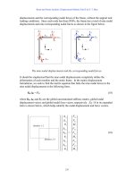
B-2. Derive the relationship for the winding distribution factor k
d
in Equation B-22.
S
OLUTION
The above illustration shows the case of 5 slots per phase, but the results are general. If there
are 5 slots per phase, each with voltage
Ai
E , where the phase angle of each voltage increases by
γ°
from
slot to slot, then the total voltage in the phase will be
AnAAAAAA
EEEEEEE ++++++=
54321
The resulting voltage
A
E
can be found from geometrical considerations. These “n” phases, when
drawn end-to-end, form equally-spaced chords on a circle of radius R. If a line is drawn from the center of
a chord to the origin of the circle, it forma a right triangle with the radius at the end of the chord (see
voltage
5A
E
above). The hypotenuse of this right triangle is R, its opposite side is
2/E
, and its smaller
angle is
2/
γ
. Therefore,
R
E 2/
2
sin =
γ
⇒
2
sin
2
1
γ
E
R =
(1)
The total voltage
A
E
also forms a chord on the circle, and dropping a line from the center of that chord to
the origin forms a right triangle. For this triangle, the hypotenuse is R, the opposite side is
2/
A
E
, and the
angle is
2/
γ
n . Therefore,
R
En
A
2/
2
sin =
γ
⇒
2
sin
2
1
γ
n
E
R
A
= (2)
Combining (1) and (2) yields
290
2
sin
2
1
2
sin
2
1
γγ
n
EE
A
=
2
sin
2
sin
γ
γ
n
E
E
A
=
Finally,
2
sin
2
sin
γ
γ
n
n
nE
E
k
A
d
==
since
d
k
is defined as the ratio of the total voltage produced to the sum of the magnitudes of each
component voltage.
B-3. A three-phase four-pole synchronous machine has 96 stator slots. The slots contain a double-layer winding
(two coils per slot) with four turns per coil. The coil pitch is 19/24.
(a) Find the slot and coil pitch in electrical degrees.
(b) Find the pitch, distribution, and winding factors for this machine.
(c) How well will this winding suppress third, fifth, seventh, ninth, and eleventh harmonics? Be sure to
consider the effects of both coil pitch and winding distribution in your answer.
S
OLUTION
(a) The coil pitch is 19/24 or 142.5°. Note that these are electrical degrees. Since this is a 4-pole
machine, the coil pitch would be 71.25 mechanical degrees.
There are 96 slots on this stator, so the slot pitch is 360
°
/96 = 3.75 mechanical degrees or 7.5 electrical
degrees.
(b) The pitch factor of this winding is
947.0
2
5.142
sin
2
sin =
°
==
ρ
p
k
The distribution factor is
2
sin
2
sin
γ
γ
n
n
k
d
=
The electrical angle
γ
between slots is 7.5
°
, and each phase group occupies 8 adjacent slots. Therefore, the
distribution factor is
291
()( )
956.0
2
15
sin 8
2
158
sin
2
sin
2
sin
=
°
°
==
γ
γ
n
n
k
d
The winding factor is
()()
905.00.956 947.0 ===
dpw
kkk
B-4. A three-phase four-pole winding of the double-layer type is to be installed on a 48-slot stator. The pitch of
the stator windings is 5/6, and there are 10 turns per coil in the windings. All coils in each phase are
connected in series, and the three phases are connected in
∆
. The flux per pole in the machine is 0.054 Wb,
and the speed of rotation of the magnetic field is 1800 r/min.
(a) What is the pitch factor of this winding?
(b) What is the distribution factor of this winding?
(c) What is the frequency of the voltage produced in this winding?
(d) What are the resulting phase and terminal voltages of this stator?
S
OLUTION
(a) The pitch factor of this winding is
966.0
2
150
sin
2
sin =
°
==
ρ
p
k
(b) The coils in each phase group of this machine cover 4 slots, and the slot pitch is 360/48 = 7.5
mechanical degrees or 15 electrical degrees. Therefore, the distribution factor is
()( )
958.0
2
15
sin 4
2
15 4
sin
2
sin
2
sin
=
°
°
==
γ
γ
n
n
k
d
(c) The frequency of the voltage produces by this winding is
()()
Hz60
120
poles 4r/min 1800
120
===
Pn
f
m
e
(d) There are 48 slots on this stator, with two coils sides in each slot. Therefore, there are 48 coils on the
machine. They are divided into 12 phase groups, so there are 4 coils per phase. There are 10 turns per
coil, so there are 40 turns per phase group. The voltage in one phase group is
( )()()( )( )
V 533 Hz60 Wb 0.054 0.958 0.966 turns4022 ===
πφπ
edpPG
fkkNE
There are two phase groups per phase, connected in series (this is a 4-pole machine), so the total phase
voltage is
V 10662 ==
G
EV
φ
. Since the machine is
∆
-connected,
V 1066==
φ
VV
T
B-5. A three-phase Y-connected six-pole synchronous generator has six slots per pole on its stator winding. The
winding itself is a chorded (fractional-pitch) double-layer winding with eight turns per coil. The
distribution factor
k
d
= 0.956, and the pitch factor k
p
= 0.981. The flux in the generator is 0.02 Wb per
292
pole, and the speed of rotation is 1200 r/min. What is the line voltage produced by this generator at these
conditions?
S
OLUTION
There are 6 slots per pole
×
6 poles = 36 slots on the stator of this machine. Therefore, there are
36 coils on the machine, or 12 coils per phase. The electrical frequency produced by this winding is
()()
Hz60
120
poles 6r/min 1200
120
===
Pn
f
m
e
The phase voltage is
()()()( )()
V 480 Hz60 Wb 0.02 0.956 0.981 turns9622 ===
πφπ
φ
edpP
fkkNV
Therefore, the line voltage is
V 8313 ==
φ
VV
L
B-6.
A three-phase Y-connected 50-Hz two-pole synchronous machine has a stator with 18 slots. Its coils form
a double-layer chorded winding (two coils per slot), and each coil has 60 turns. The pitch of the stator coils
is 8/9.
(a) What rotor flux would be required to produce a terminal (line-to-line) voltage of 6 kV?
(b) How effective are coils of this pitch at reducing the fifth-harmonic component of voltage? The seventh-
harmonic component of voltage?
S
OLUTION
(a) The pitch of this winding is 8/9 = 160
°
, so the pitch factor is
985.0
2
160
sin =
°
=
p
k
The phase groups in this machine cover three slots each, and the slot pitch is 20 mechanical or 20 electrical
degrees. Thus the distribution factor is
()( )
960.0
2
20
sin 3
2
20 3
sin
2
sin
2
sin
=
°
°
==
γ
γ
n
n
k
d
The phase voltage of this machine will be
()( )()()()
Hz50 0.960 0.985 l turns/coi60 coils 622
φπφπ
φ
==
edpP
fkkNV
φ
φ
75621=V
The desired phase voltage is 6 kV /
3
= 3464 V, so
Wb 046.0
75621
V 3464
==
φ
(b) The
fifth harmonic:
()( )
643.0
2
160 5
sin =
°
=
p
k
The
seventh harmonic:
()( )
342.0
2
160 7
sin −=
°
=
p
k
293
Since the fundamental voltage is reduced by 0.985, the fifth and seventh harmonics are suppressed relative
to the fundamental by the fractions:
5
th
:
653.0
985.0
643.0
=
7
th
: 347.0
985.0
342.0
=
In other words, the 5
th
harmonic is suppressed by 34.7% relative to the fundamental, and the 7
th
harmonic is
suppressed by 65.3% relative to the fundamental frequency.
B-7. What coil pitch could be used to completely eliminate the seventh-harmonic component of voltage in ac
machine armature (stator)? What is the minimum number of slots needed on an eight-pole winding to
exactly achieve this pitch? What would this pitch do to the fifth-harmonic component of voltage?
S
OLUTION
To totally eliminate the seventh harmonic of voltage in an ac machine armature, the pitch factor
for that harmonic must be zero.
2
7
sin0
ρ
==
p
k
⇒
()
n 180
2
7
°=
ρ
, n = 0, 1, 2, …
()
7
1802 n°
=
ρ
In order to maximize the fundamental voltage while canceling out the seventh harmonic, we pick the value
of n that makes
ρ
as nearly 180
°
as possible. If n = 3, then
ρ
= 154.3
°
, and the pitch factor for the
fundamental frequency would be
975.0
2
3.154
sin =
°
=
p
k
This pitch corresponds to a ratio of 6/7. For a two-pole machine, a ratio of 6/7 could be implemented with
a total of 14 slots. If that ratio is desired in an 8-pole machine, then 56 slots would be needed.
The fifth harmonic would be suppressed by this winding as follows:
()( )
434.0
2
3.154 5
sin =
°
=
p
k
B-8. A 13.8-kV Y-connected 60-Hz 12-pole three-phase synchronous generator has 180 stator slots with a
double-layer winding and eight turns per coil. The coil pitch on the stator is 12 slots. The conductors from
all phase belts (or groups) in a given phase are connected in series.
(a) What flux per pole would be required to give a no-load terminal (line) voltage of 13.8 kV?
(b) What is this machine’s winding factor
k
w
?
S
OLUTION
(a) The stator pitch is 12/15 = 4/5, so
°= 144
ρ
, and
951.0
2
144
sin =
°
=
p
k
294
Each phase belt consists of (180 slots)/(12 poles)(6) = 2.5 slots per phase group. The slot pitch is 2
mechanical degrees or 24 electrical degrees. The corresponding distribution factor is
()( )
962.0
2
24
sin .52
2
24 5.2
sin
2
sin
2
sin
=
°
°
==
γ
γ
n
n
k
d
Since there are 60 coils in each phase and 8 turns per coil, all connected in series, there are 480 turns per
phase. The resulting voltage is
()()()()
Hz60 0.962 0.951 turns48022
φπφπ
φ
==
edpP
fkkNV
061,117
φ
φ
=V
The phase voltage of this generator must be
V 79673 / kV 8.13 =
, so the flux must be
Wb 068.0
117,061
V 9677
==
φ
(b) The machine’s winding factor is
()()
915.00.962 0.951 ===
dpw
kkk